SPEWE Isoturbo 5305S-30 2014 User manual

1903451 | 02-2014 | Spewe.ch
Isoturbo
®
5305S-30
1
GB
CZ
DE
Glühdraht-Schneidegerät
Sicherheitshinweise 2
Bedienungsanleitung 3-11
Ersatzteilliste 12
FR
Découpeuse a filament chauffant
Instructions de sécurité 2
Mode d’emploi type 3-11
Liste pièces de rechange 12
IT
Trancia a filo incandescente
Avvisi di sicurezza 2
Istruzioni per l’uso modello 3-11
Elenco dei pezzi di ricambio 12
Heated Wire Cutting Device
Safety Instructions 2
Operating Instructions 3-11
Replacement Parts 12
Řezačka se žhavicím drátem
Bezpečnostní pokyny 2
Návod k obsluze 3-11
Seznam náhradních dílů12
Isoturbo
®
5305S-30
Mod. 2014
Art.-Nr. 1000163 (EU)
Art.-Nr. 1000164 (EU)
Art.-Nr. 1000168 (CH)
Art.-Nr 1000169 (CH)

2
Isoturbo
®
5305S-30
1903451 | 02-2014
D
Sicherheitshinweise - Vorwort
Diese Anleitung ist die Grundlage zur Bedienung des Glühdraht-Schneidegeräts. Sie verdient Ihre volle Aufmerksamkeit. Bevor
Sie mit irgendwelchen Arbeiten an oder mit dem Gerät beginnen, verpflichten wir Sie, die vorliegende Anleitung und die separa-
ten Sicherheitsbestimmungen bis zum Schluss sorgfältig durchzulesen. Bestehen irgendwelche Unklarheiten, sprechen Sie
uns umgehend dazu an. Nehmen Sie das Gerät nicht in Betrieb solange Unklarheiten bestehen. Mit der Inbetriebnahme des
Gerätes bestätigen Sie, dass Sie die Anleitung gelesen und verstanden haben und somit die Betriebsverantwortung übernom-
men haben.
Lieferumfang: Glühdraht-Schneidegerät Typ 5305S mit integriertem Trafo, Freistellstütze, Torx-Stiftschlüssel,
Gabelschlüssel M6/M5, Anleitung. Optional: Transport- und Aufbewahrungskoffer.
Technische Daten:
Schnittlänge: 104 cm | Schnitttiefe: 30.5 cm | Gewicht Gerät: 17.2 kg
Zuschnitt : Thermisch | Stromversorgung: 230V / 50 Hz
F
Remarques de sécurité concernant les coupeuses à filament incandescent – Préface
Ce mode d’emploi est la base pour le maniement de la coupeuse à filament incandescent. Veuillez le consulter avec beaucoup
d’attention. Avant de commencer quelques travaux que ce soit ou avant d’utiliser la coupeuse, nous vous engageons à lire le
présent mode d’emploi et les remarques de sécurité séparé a minutieusement jusqu’à la fin. S’il y a quelques confusions,
n’hésitez pas à nous contacter immédiatement. Ne mettez pas la coupeuse en service tant qu’il y a des confusions. Avec la
mise en service de la coupeuse, vous confirmez que vous avez lu le mode d’emploi et que vous l’avez compris et ainsi vous
prenez en charge la responsabilité du bon fonctionnement.
Volume de livraison : Découpeuse à filament chauffant type 5305S à transformateur intégré, béquilles de suport, clé mâle
coudée, clé à fourche M6/M5, mode d’emploi. En option: mallette de transport et de protection.
Caractéristiques techniques :
Longueur de coupe: 104 cm | Profondeur de coupe 30.5 cm | Poids de l’appareil: 17.2 kg
Découpe : thermique | Alimentation : 230V / 50 Hz
I
Avvisi di sicurezza per la trancia a filo incandescente - Premssa
Le presenti istruzioni sono la base per l’uso della taglierina a filo incandescente.
Prima di iniziare qualsiasi operazione sull’apparecchio o con l’apparecchio, vi chiediamo di impegnarvi a leggere attentamente
le presenti istruzioni e la avvertenze di sicurezza separato fino alla fine. Qualora dovessero esservi dei punti non chiari, contat-
tateci immediatamente e parlatecene. Non mettete in funzione l’apparecchio fino a quando sussistono questi dubbi. Mettendo in
funzione l’apparecchio, confermate di avere letto le istruzioni e di esservi assunto la responsabilità del relativo esercizio.
Corredo di fornitura : Trancia a filo incandescente modello 5305S con trasformatore integrato, supporto per il montaggio libe-
ro, chiave per il perno Torx, chiave per la forcella M6/M5, , istruzioni per l’uso.
Optionale: valigetta per il trasporto e la custodia.
Dati tecnici:
Lunghezza di taglio: 104 cm | Profondità di taglio: 30.5 cm | Peso dell’apparecchio: 17.2 kg
Taglio: termico | Alimentazione: 230V / 50 Hz
GB
Hot wire cutter safety advice and instructions manual - Foreword
These instructions must be read before using the hot wire cutter. Please read them carefully.
Before you begin any work or begin using the tool, you must carefully read this introduction and the separate safety advice . If
you have any queries, please do not hesitate to contact us. Do not use the tool if you continue to be unsure about any aspect.
When you begin to use the tool, you tacitly confirm that you have read and understood the introduction and that you take full re-
sponsibility for the operation of the tool.
Scope of delivery: Heated wire cutting device Type 5305S with integrated transformer, free-stand strut, Torx-pin spanner, flat
spanner M6/M5, operating instructions. Optional: Transportation- and storage case.
Technical details:
Cutting length: 104 cm | Cutting depth: 30.5 cm | Equipment weight: 17.2 kg
Cut: Thermal | Power supply: 230V / 50 Hz
CZ
Bezpečnostní pokyny - Předmluva
Tato příručka je základem pro obsluhu řezačky se žhavicím drátem. Zaslouží si Vaši plnou pozornost. Než začnete jakoukoli
práci na zařízení nebo se zařízením, měli byste si pečlivěpročíst tento návod až a samostatný bezpečnostní politiky pečlivěaž
do konce. V případějakýchkoli nejasností se na nás ihned obraťte. Zařízení neuvádějte do provozu, dokud existují nejasnosti.
Uvedením zařízení do provozu potvrzujete, že jste si přečetli návod a porozuměli mu, čímž na sebe přebíráte odpovědnost za
jeho provoz.
Objem dodávky:
řezačka se žhavicím drátem typ 5305S s integrovaným trafem, volněnastavitelná podpěra, nástrčkový klíčs čepy, rozvidlený
klíčM6/M5, návod k obsluze. volitelnýkufr pro přepravu a úschovu.
Technické údaje:
Délka řezu: 104 cm | Hloubka řezu: 30,5 cm | Hmotnost přístroje: 17,2 kg
Řezání: tepelné | Napájení: 230 V / 50 Hz
1903451 | 02-2014 | Spewe.ch
Isoturbo
®
5305S-30
3
Inbetriebnahme / Installation / Messa in funzione / Setting the Device Up / Uvedení do provozu
1
Fig. 1
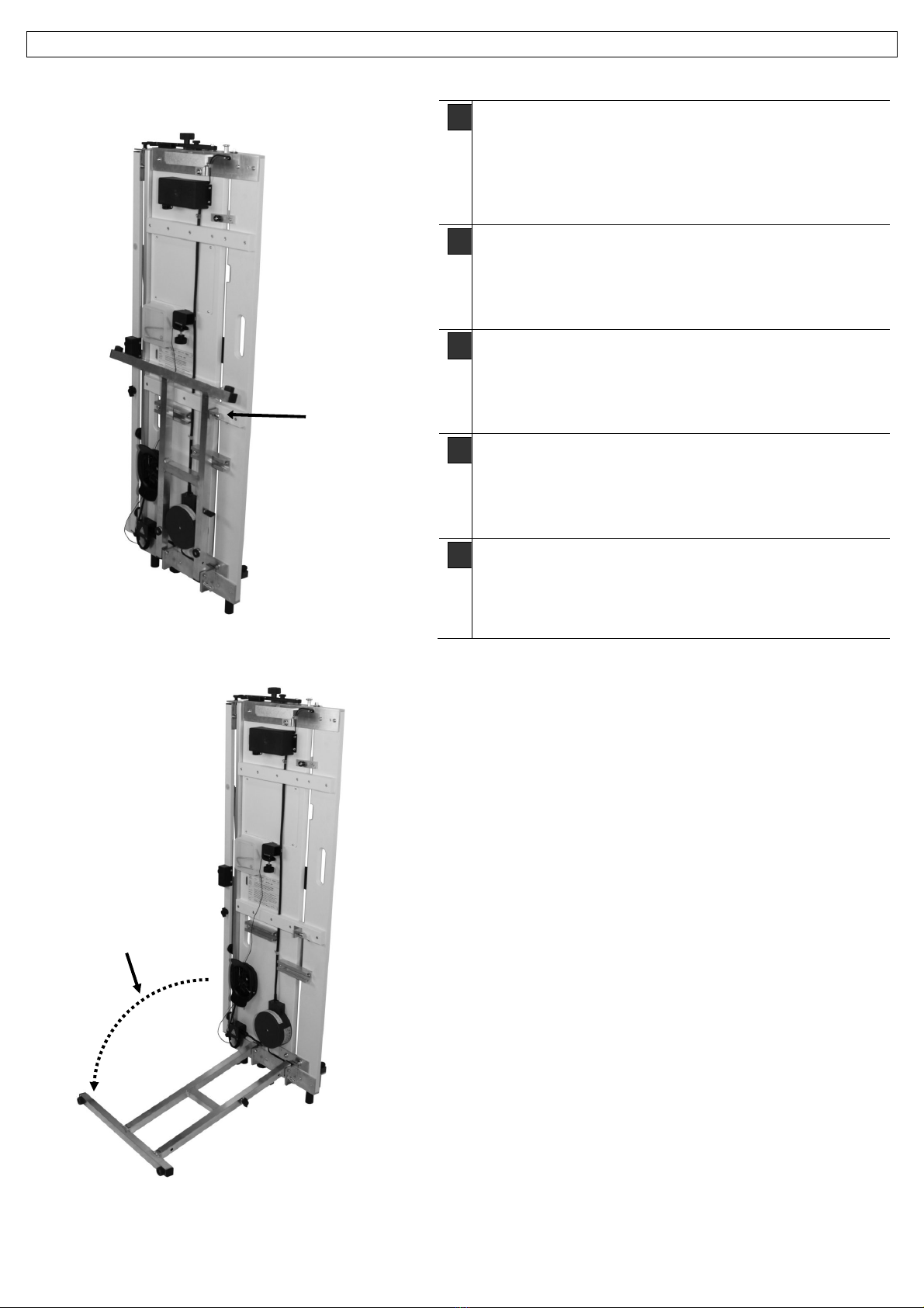
D
Koffer öffnen, Schneidegerät an der Holzbrett-
Griffmulde aus dem Koffer heben und senkrecht auf
den Boden stellen.
Klappfuss-Sicherung [1] entriegeln und Fuss ab-
schwenken [2]
F
Ouvrir la mallette et retirez l‘appareil en le saisissant
par la poignée en encastrée de la plaque de bois.
Déverrouillez la sécurité du pied repliable [1] et dé-
pliez le pied [2]
I
Aprire la valigetta ed estrarre la trancia dalla valiget-
ta attraverso l’impugnatura della tavola di legno
Sbloccare il piedino ribaltabile [1]e oscillarlo verso il
basso [2].
GB
Open case and lift the cutting device out of thecase
by the recessed wooden grip
Unlock safety catch on of rear stand [1] and pull out
rear stand [2]
CZ
Otevřete kufr, vyndejte řezačku za dřevěnou rukojeť
z kufru a postavte svisle na podlahu.
Odblokujte pojistku sklápěcí nohy [1] a nohu
vyklopte [2]
2
Fig. 2

4
Isoturbo
®
5305S-30
1903451 | 02-2014
Inbetriebnahme / Installation / Messa in funzione / Setting the Device Up / Uvedení do provozu
Fig. 3
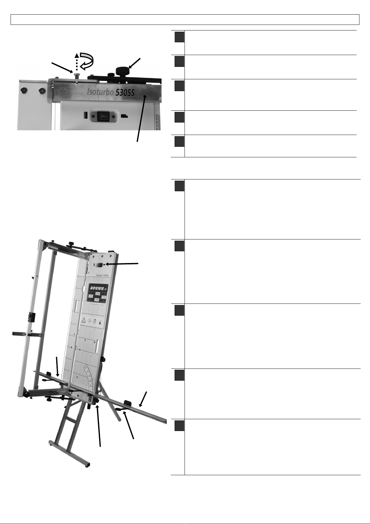
D
Klappfuss mittels Zugschnäpper [3] gegen ungewolltes Ein-
klappen sichern. Auf dem Gerüst kann das Gerät auf die Ge-
rüstlade gestellt und an der Wand montagefrei angelehnt wer-
den. Der nach vorne abgewinkelte Fuss ermöglicht, dass das
Gerät den Hohlraum zwischen Wand und Gerüstlade ausnutzt.
Damit ergibt sich eine grössere Durchgangsfreiheit auf dem
Gerüst.
Um das Gerät freizustellen muss die im Koffer mitgelieferte
Freistellstütze [4] in die Freistellstützenhalterung eingeschoben
und mittels Klemmhebel festgezogen werden. Strebe [5] ab-
schwenken und an Klappfuss mit Flügelgriff [6] sichern.
F
Sécurisez le pied repliable au moyen du verrou à traction [3]
contre toute fermeture involontaire. Sur l’échafaudage, on peut
le poser sur la plateforme et on peut l’appuyer contre un mur
sans avoir faire de montage. Le pied incurvé vers l’avant per-
met à l’appareil d’utiliser l’espace creux situé entre le mur et la
plateforme d’échafaudage. Le passage sur l’échafaudage est
donc plus facile.
Pour pouvoir installer l’appareil de façon autonome il faut enfi-
ler les béquilles livrées [4] dans la mallette dans les attaches
prévues à cet effet et assurer avec un levier de blocage. Dé-
pliez le contrefort [5] et sécurisez le sur le pied repliable à l’aide
de la vis à ailettes [6].
I
Bloccare il piedino ribaltabile per mezzo dello scatto a traino [3]
contro un ribaltamento indesiderato. Può essere adagiato sul
battente dell‘incas-tellatura sull’incastellatura stessa e in segui-
to lo si può appoggiare al muro senza montaggio. Il piede ribal-
tato verso avanti offre la possibilità all’at-trezzo di sfruttare la
cavità tra il muro e il battente dell’incastellatura. Con questo ri-
sulta una maggiore libertà di transito sul battente
d‘incastellatura.
Per poter montare liberamente l’attrezzo il supporto per il mon-
taggio libero consegnato nella valigetta deve essere inserito [4]
nel dispositivo di supporto per il montaggio libero e in seguito
fissato con la leva ad incastro. Oscillare la gamba [5] verso il
basso e fissarla all’impugnatura ad ala [6].
GB
Secure rear stand with snap catch [3] to prevent from collaps-
ing. It can be set on the scaffold tray on the scaffold and
leaned against a wall without any assembly. When forward-
bend of the foot makes it possible for the device to use the
empty space between the wall and the scaffold tray. This pro-
duces greater pass-throughaccess on the scaffold.
In order to make the device free-standing, the free-standing [4]
strut included in the case must be inserted into the bracing
point [bracket] provided for the free-standing strut and secured
with the clamping lever. Pull out strut [5] and secure to rear
stand with butterfly handle [6]
CZ
Vyklápěcí nohu zajistěte proti nechtěnému sklopení
prostřednictvím západky [3]. Na lešení lze zařízení položit na
patro lešení a bez montáže opřít o stěnu. Noha směřující
dopředu umožňuje, aby zařízení využilo prostor mezi stěnou a
patrem lešení. Tím se na lešení dosáhne většího prostoru pro
průchod.
5
4
6
3
Fig. 4
1903451 | 02-2014 | Spewe.ch
Isoturbo
®
5305S-30
5
Inbetriebnahme / Installation / Messa in funzione / Setting the Device Up / Uvedení do provozu
D
Griffschraube [7] oben und unten lösen, Schneidbügel-
Transportsicherung [8] entriegeln und Schneidbügel [9] auf-
klappen. Griffschrauben [7] wieder festziehen.
F
Dévissez les vis à poignée [7] en haut et en bas, déverrouil-
lez la sécurité de transport de l’étrier de coupe [8] et dépliez
l’étrier de coupe [9]. Resserrez les vis à poignée [7]
I
Allentare la vite dell’impugnatura [7] superiore ed inferiore,
sbloccare il dispositivo di bloccaggio di trasporto della staffa
da taglio [8] e ribaltare la staffa da taglio [9]. Fissare
nuovamente le viti dell‘impugnatura [7].
GB
Release handle screw [7] at top and bottom, unlock trans-
portation safety catch on cutting bow [8] and fold out cutting
bow [9]. Re-tighten handle screws [7].
CZ
Povolte šrouby s rýhovanou hlavou [7] nahoře a dole,
odblokujte přepravní pojistku řezacího oblouku [8] a řezací
oblouk [9] vyklopte. Šrouby opět utáhněte [7].
8
7
9
D
Schrägstellreiter [10] lösen und nach unten gleiten lassen.
Auflageschiene [11+12] abschwenken. 3 Auflageverbreitun-
gen [13] unter den Auflageschienen ausklappen. (Verhindern
ein Abkippen dicker Dämmplatten) Gerät an Stromnetz an-
schliessen. Das Gerät ist nun einsatzbereit und kann mittels
Wippenschalter [14] in Betrieb genommen werden: Schalter
nach links drücken = langer Draht wird heiss. (Rechts wird
der als Zubehör erhältliche Eckschneider eingeschaltet)
F
Déverrouillez le cavalier de réglage d’inclinaison [10] et le guider
vers le bas. Inclinez le rail de guidage [11+12]. Dépliez 3 élar-
gisseurs de guidage [13] en dessous des rails de guidage (em-
pêche le basculement de plaques d’isolant épaisses). Raccor-
dez l’appareil au réseau. L’appareil est maintenant prêt à être
utilisé et peut être mis en service au moyen d’un interrupteur à
bascule [14] : poussez le bouton vers la gauche = le fil long se
réchauffe. (En poussant le bouton vers la droite, on met en ser-
vice le système de découpe en angle disponible en accessoire).
I
Allentare il cavalletto inclinato [10] e farlo scivolare verso il bas-
so. Far oscillare verso il basso la guida di supporto
[11+12]
. Ri-
baltare i 3 ampliamenti del supporto [13] sotto le guide di sup-
porto. (Eviti il ribaltamento di piattaforme di isolamento spesse).
Collegare l’apparecchio alla rete elettrica. L’apparecchio ora è
pronto all’uso e può essere messo in uso mediante l’interruttore
ad altalena [14]: premere l’interruttore verso sinistra = si scalda
il filo di ferro lungo. (A destra si accende il dispositivo da taglio
ad angolo fornito quale accessorio)
GB
Release bevelled rider [10] and let it slide down. Pull out bearing
rail [11+12]. Pull out 3 support devices [13] under the bearing
rail. (Prevent thick softboard from tipping). Connect machine to
ther mains. The machine is now ready to be used and can be
started by means of a rocker switch [14]: press switch to the
left = long wire will get hot. (The corner cutter, available as addi-
tional accessory is switched on to the right)
CZ
Povolte jezdce naklápěcího podstavce [10] a nechte ho vyjet
směrem dolů. Odklopte lištu pro uložení materiálu [11+12]. Pod
lištami rozklopte 3 držáky rozšíření uložení materiálu [13]. (Brání
překlopení tlustých izolačních panelů) Zařízení připojte k síti
230 V. Zařízení je nyní připraveno k použití a lze je
prostřednictvím kolébkového spínače [14] uvést do provozu:
spínačstlačte doleva = rozpálí se dlouhý drát. (doprava se
zapne jako příslušenství úhlové řezačky)
10
11
12
13
14
Fig. 5
Fig. 6
6
Isoturbo
®
5305S-30
1903451 | 02-2014
Schnittvarianten / Variantes de coupes / Varianti di taglio / Cutting variants / Varianty řezů
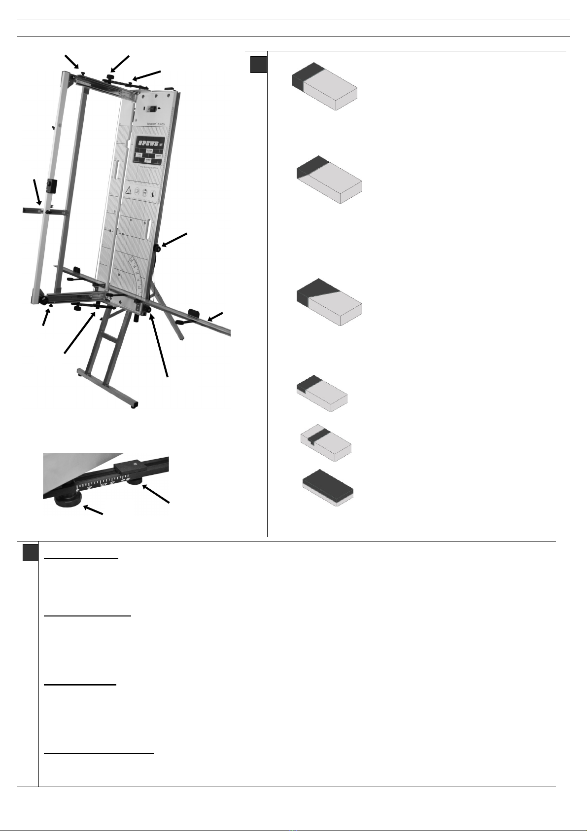
D
Gerader Schnitt:
Dämmplatte auf
Auflageschienen legen, Schneidebügel
ausziehen, Dämmplatte bis zum Zuschnitt-
mass oder aufgesetztem Anschlag schie-
ben und Bügel durch Dämmplatte stossen.
Zur Verminderung der Rauchentwicklung bitte Gerät nach er-
folgtem Schnitt ausschalten.
Gehrungsschnitt:
Gehrung vom Objekt
abnehmen und auf Dämmplatte übertra-
gen, Platte auf Auflageschiene stellen,
Schneidebügel ausziehen, Dämmplatte mit
Markierung bis zur Mitte der Brettnut vor
schieben, Schneidebügel nach rechts ab-
schwenken bis Draht mit vorderer Markierung übereinstimmt.
Gehrungsreiter [15] oben und unten an Griffschraube [7] schieben
und fixieren. Nun bleibt die Gehrung für Schnittwiederholungen
eingestellt.
Schrägschnitt:
Schräge einmalig auf
Dämmplatte übertragen und auf Auflage
schiene stellen. Schneidebügel ausziehen,
Auflage [12] mit Dämmplatte anheben bis
Draht mit Kennzeichnung übereinstimmt,
Reiter [10] bis zur Auflage hochschieben
und fixieren. Reiter [16] bis zum Reiter [10] führen und fixieren.
Nun bleibt die Schräge für Schnittwiederholungen eingestellt.
Falz-Auftrennschnitt:
Schneidebügel
bis zum gewünschten Falz- oder Auf-
trennmass ausziehen, entweder Tiefenbe-
grenzer [17] abschwenken oder Schrauben
[18] oben und unten leicht fixieren.
F
Découpe droite :
Posez les panneaux sur les barres d’appui, tirez la ferrure de coupe, poussez les panneaux jusqu’au repère de dé-
coupe ou à la butée préréglée et appuyez fortement la ferrure de découpe sur les panneaux. Pour réduire le plus
possible le dégagement de fumée, arrêtez l’appareil après chaque opération.
Découpe à onglet :
Retirez l’onglet de l’objet et transférez-le sur les panneaux, posez la plaque sur les barres d‘appui, tirez la ferrure de
découpe, poussez les panneaux isolants jusqu’au milieu de la goujure de plaque, faites basculer la ferrure de coupe
vers la droite jusqu’à ce que le fil soit aligné sur la marque avant. Faites glisser les cavaliers [15] du haut et du bas
vers les poignées étoiles [7] et fixez les. L’onglet est alors réglé pour des coupes répétées.
Coupe en biais :
Rapportez la ligne biaise sur les panneaux et posez-les sur les barres d’appui. Tirez la ferrure de découpe, relevez le
support avec les panneaux jusqu’à ce que le fil soit aligné sur les repères, remontez le cavalier [10] jusqu’au support
et fixez-le. Amenez le cavalier [16] jusqu’au cavalier [10] et fixez-le. La ligne biaise est alors fixée pour des coupes
répétées.
Découpe d’une rainure:
Positionner le fil chaud à la profondeur souhaitée, puis ajuster le taquet de profondeur [17] soit serrer légèrement
les vis en haut et en bas [18]
15
15
7
15
7
16
10
17
18
18
Fig. 7
Fig. 8
12

1903451 | 02-2014 | Spewe.ch
Isoturbo
®
5305S-30
7
Schnittvarianten / Variantes de coupes / Varianti di taglio / Cutting variants / Varianty řezů
I
Taglio dritto:
Collocare la piastra isolante sulla barra di posizione ed estrarre la staffa da taglio, spingere la piastra isolante fino alla
misura del taglio o fino all’arresto precedentemente inserito e attestare la staffa attraverso la piastra isolante. La pre-
ghiamo di spegnere l’attrezzo dopo il taglio eseguito per evitare la formazione di fumo.
Taglio per giunti ad angolo:
Staccare il giunto ad angolo e trascriverlo sulla piastra isolante, adagiare la piastra sulla barra di posizione, estrarre la
staffa da taglio, spingere la piastra isolante insieme alla marcatura fino alla metà della scanalatura della tavola, ribalta-
re la staffa da taglio verso destra fino a che il filo coincide con la marcatura frontale. Spingere il cavalletto [15] sopra e
sotto verso i manici a stella [7] e fissar lo. Il giunto ad angolo ora rimane sinto nizzato per le ripetizioni dei tagli.
Taglio trasversale:
Trascrivere unicamente l’inclinazione sulla piastra isolante e collocare quest’ultima sulla barra di po si zione. Estrarre
la staffa da taglio, alzare la barra con la piastra isolante fino a che il filo corri sponde alla marcatura. Spingere il caval-
letto [10] verso l’alto fino alla barra e fissarlo. Dirigere il cavalletto [16] fino al cavalletto [10] e fissarlo. L’inclinazione
ora rimane sintonizzata per le ripetizioni dei tagli.
Taglio di disfacimento della scanalatura:
Estrarre la staffa da taglio fino alla scanalatura desiderata o fino alla misura del disfacimento, fissare leggermente le
viti di limitazione della profondità [18] sopra e sotto.
GB
Straight Cut:
Set the insulating plate on the right bearing rail and pull out the cutting clamp. Shove the insulating plate to the cutting
measure - or to the arrester guide. Activate the device and push the clamp through the insulating plate. To reduce
the production of smoke and fumes, turn the device off after making the cut.
Mitre Cut:
Take the mitre from the object and transfer to the insulating plate, set the plate on bearing rail, pull out the cutting
clamp, push the insulating plate with the marking forward to the middle of the board nut, swing the cutting clamp down
to the right until the wire lines up with the marking. Push the mitre slide [15] top and bottom to the star grips [7] and
lock. Now the mitre will stay fixed for repeated cuts.
Bevel cut:
Transfer the roof pitch once to the insulating plate and the insulating plate on the bearing rail. Pull out the cutting
clamp, lift the rail until the wire lines up with the marking. Raise the angle slide [10] to the rail and lock it. Traverse
slide [16] to slide [10] and lock. Now the bevel will be set for repeated cutting.
Rabbet-Seam Cut:
Pull out the cutting clamp to the desired rabbet or seam width, slightly tighten depth governing screws [18] top and bot-
tom.
CZ
Přímý řez:
Izolační panel položte na lišty uložení materiálu, vytáhněte řezací oblouk, panel posunujte až k rozměru přířezu nebo
nastavenému dorazu a oblouk táhněte skrze panel. Pro zamezení vzniku kouře zařízení po provedení řezu
vypněte.
Řezání na pokos:
Pokos změřte a přeneste z objektu na panel, položte panel na lištu uložení materiálu, vytáhněte oblouk řezání, panel
se značkou posouvejte až ke středu žlábku, obloukem zatočte doprava, až se drát dostane k přední značce. Jezdce
pokosu [15] posuňte pomocí šroubu s rýhovanou hlavou [7] nahoru a dolůa upevněte. Nyní je pokos nastaven pro
opakované řezání.
Šikmý řez:
Přeneste zkosení na panel a položte jej na lištu pro uložení materiálu. Vytáhněte řezací oblouk, zdvihněte uložení [11]
panelu až se drát bude shodovat s označením na panelu, posuňte jezdce [10] nahoru až k uložení materiálu a
upevněte jej. Posuňte jezdce [16] až k jezdci [10] a upevněte. Nyní je zkosení nastaveno pro další řezání.
Řez pro vytvoření drážky a řez pro oddělení:
Řezací oblouk vytáhněte až k požadovanému rozměru drážky nebo místu oddělení, buďsklopte omezovačhloubky
[17] nebo lehce upevněte šrouby [18] nahoře a dole.
8
Isoturbo
®
5305S-30
1903451 | 02-2014
Schnittausführung mit Turbo / Exécution de la coupe au Turbo / Esecuzione del taglio con il
turbo / Cutting with the turbo / Turbo Sekce
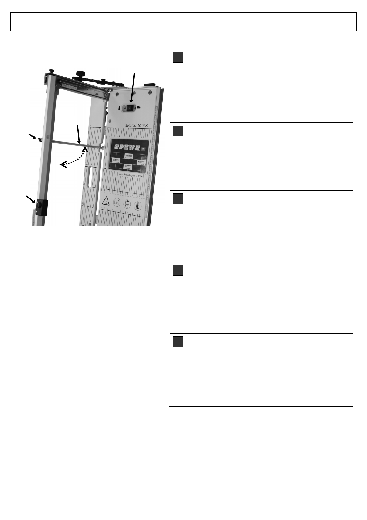
D
Turbostab [19] waagrecht stellen, bis Draht zwischen
U/Kontakt geführt ist.
Flügelgriff [20] festziehen. Durch Drücken des Turbo
Drucktasters [21] – bei eingeschaltetem Gerät [14] –
wird der Draht zwischen Turbokontakt und unterer
Drahtführungsrolle stärker erhitzt.
Der Draht wird somit nur dann heisser, wenn dies
auch durch einen Zuschnitt gewünscht wird. Das
schont den Trafo und den Draht.
F
Placez la barre Turbo [19] à l’horizontale.
Resserrez la vis papillon [20]. En pressant le bouton
poussoir de Turbo [21], lorsque l’appareil est branché
[14], on déclenche le chauffage du filament située
entre le turbo-contact et le rouleau guide inférieur de
filament. Le filament chauffera uniquement lorsque
ceci est requis par une coupe. On ménage ainsi le
transformateur et le filament.
I
Posizionare l’asta del turbo [19] in posizione verticale.
Stringere bene il manico ad alette [20]. Premendo
l’interruttore del turbo [21] – con l’attrezzo inserito [14]
– il filo si riscalda maggiormente tra lo contato di turbo
ed il rullo conduttore del filo.
Il filo viene quindi maggiormente riscaldato soltanto se
si desidera effettuare un determinato taglio. Ciò ri-
sparmia il trasformatore e il filo.
GB
Set Turbo rod [19] horizontal.
Tighten the butterfly grip [20]. By pressing the Turbo-
pressure button [21] – with the device activated [14] –
the wire between the turbocontact and the lower wire
guide roller will be heated more intensely.
The wire thus only becomes hotter if this is desired for
a particular cut. This spares both the transformer and
the wire.
CZ
Tyčturba [19] nastavte vodorovně, až drát povede
mezi U/kontaktem.
Utáhněte křídlovou úchytku [20]. Zmáčknutím turbo
tlačítka [21] – při zapnutém zařízení [14] – se silněji
rozžhaví drát mezi turbokontaktem a spodním vodicím
válečkem drátu.
Drát se takto rozžhaví jenom poté, pokud je to
požadováno i ze strany řezání. Šetří to trafo a drát.
19
20
21
Fig. 9
14

1903451 | 02-2014 | Spewe.ch
Isoturbo
®
5305S-30
9
Justierung / Ajustage / Torsiometrica / Adjustment / Nastavení
Störungsursachen / Les problèmes potentiels / Potenziali problemi / Potential problems / Příčiny poruch
F
Causes de défauts/reparations - Contacts
Le passage du courant du transformateur au filament chauffant se fait par les torons de câbles supérieurs et inféri-
eurs [24] placés directement sur le profilé de charnière.
En cas de problèmes sur les contacts (contact intermittent, etc.) vérifiez le logement des raccords de câbles
et nettoyez les rails de roulements à billes.
I
Cause di disturbi / Rimedi ai disturbi - Contatti
Il percorso della corrente elettrica dal trasformatore al filo incandescente avviene tramite l’asse girevole sovra- e sot-
tostante [24] direttamente al profilo delle cerniera.
Se si dovessero presentare dei problemi di contatto (contatto lasco, ecc.) è necessario controllare la localiz-
zazione di questi punti di contatto.
GB
Sources of Malfunction /Troubleshooting - Contacts
The current pathway from the transformer to the heat wire proceeds over the upper and power pivot axis [24].
If contact problems occur (loose contact, sparking, etc.) the fitting of these contact points must be tested.
CZ
Příčiny / odstraňování poruch - Kontakty
Proud prochází z transformátoru ke žhavicímu drátu přes horní a dolní kabelový pramen [24] přímo k přednímu
kloubovému profilu.
V případěproblémůs kontaktem (uvolněný kontakt atd.) zkontrolujte, prosím, uložení kabelových spojek a
vyčistěte kolejničky a válečky vedení drátu. (Nepoužívejte žádné mazivo!)
D
Schnittwinkel-Justierung
Der exakte 90°-Schnitt kann Mithilfe des beiliegen-
den Gabelschlüssels, durch Nachstellen des Reiters
[22], nach justiert werden.
Die Auflageschienen können mittels Schraube [23]
links und rechts nachjustiert und mit der Viereckmut-
ter wieder gekontert werden.
22
23
Fig. 10
F
Ajustage de l’angle de coupe
La coupe perpendiculaire exacte à 90°sera réajustée à l’aide de la clé à fourche jointe à la fourniture, par réglage ad-
ditionel du coulisseau [22].
On peut réajuster les barres d’appui à l’aide de la vis [23] à gauche et à droite puis bloquer de nouveau par inversion
avec l’écrou carré.
I
Aggiustamento dell’angolo di taglio
Il taglio esatto di 90° può essere aggiustato tramite la chiave per la forcella inclusa, impostando il cavalletto [22] in una
nuova posizione.
Gli scorrimenti delle barre di posizione possono essere aggiustati tramite la vite [23] verso sinistra e verso destra e
per poi venire nuovamente fissati con il dado quadrato.
GB
Adjustment
On the slide [22], the exact 90°-cut of the cutting clamp can be re-adjusted.
The bearing rails can be re-adjusted on the right and left using the screw [23].
CZ
Nastavení úhlu řezu
Přesný řez 90° lze nastavit prostřednictvím přiloženého rozvidleného klíče pomocí přenastavení jezdce [22]. Lišty
uložení materiálu lze nastavit prostřednictvím šroubu [23] vlevo a vpravo a posléze zajistit pomocí čtverhranné matice.
D
Störungsursachen / Störungsbehebung: Kontakte
Der Stromverlauf vom Transformator zum Glühdraht er-
folgt über die obere und untere Kabellitze [24] direkt auf
das vordere Scharnierprofil.
Bei Kontaktproblemen (Wackelkontakt etc.) prüfen Sie
bitte den Sitz der Kabelverbindungen und reinigen Sie
die Kugelrollschienen und Drahtführungsrollen. (Kein
Fett verwenden!)
24
Fig. 11

10
Isoturbo
®
5305S-30
1903451 | 02-2014
Störungsursachen / Les problèmes potentiels / Potenziali problemi / Potential problems / Příčiny poruch
D
Störungsursachen / Störungsbehebung
Transformator
Der Trafo ist mit einem Thermoschutzschalter
ausgestattet. Wird der Trafo zu heiss, aktiviert sich
der Schutzschalter und verhindert einen Schaden an
der Wicklung durch übermässige Erhitzung.
Zur Abkühlung muss das Gerät vom 230V Netz
getrennt werden. Je nach Trafotemperatur kann
die Abkühlphase einige Zeit dauern.
Zudem befindet sich am Trafo ein sichtbarer
Schutzschalter [25]. Dieser reagiert, wenn ein
Kurzschluss am Gerät herbeigeführt wird. Kontrollie-
ren und beheben Sie in diesem Fall Ihr Gerät auf
mögliche Kurzschlüsse. Warten Sie einige Sekun-
den und aktivieren Sie den Reset-Knopf [25]. Sollte
der Schutzschalter wiederholt reagieren, so liegt
möglicherweise ein Defekt vor, der nur von einem
Fachmann kontrolliert und behoben werden darf.
25
F
Causes de défauts/réparations - Transformateur
Le transformateur est équipé d’un thermorupteur. En cas de surchauffe du transformateur, le thermorupteur est ac-
tionné et empêche tous dégâts de surchauffe excessive sur la bobine.
Il faut déconnecter l’appareil du réseau 230V pour qu’il refroidisse. La durée de la phase de refroidissement
varie en fonction des types de transformateurs.
Un interrupteur de protection visible se trouve sur le transformateur. Il se déclenche en cas de court-circuit sur
l’appareil. Dans ce cas, inspectez votre appareil pour isoler les éventuels courts-circuits et réparez. Attendez quelques
secondes puis appuyez sur le bouton acquittement [25]. Si l’interrupteur de protection se déclenche plusieurs fois à la
suite, il se peut qu’il y ait un défaut qui ne pourra être identifié et réparer que par un spécialiste.
I
Cause di disturbi / Rimedi ai disturbi - Trasformatore
Il trasformatore dispone di un interruttore di protezione termica. Se il trasformatore si surriscalda, viene azionato
l’interruttore di protezione che impedisce di formare dei danni al bobinaggio a causa di un surriscaldamento eccessi-
vo.
Affinché l’attrezzo si raffreddi lo si deve sconnettere dalla rete elettrica di 230V. Il raffreddamento può durare
qualche istante a seconda della temperatura del trasformatore.
Inoltre il trasformatore dispone di un interruttore di protezione visibile. La preghiamo di aspettare alcuni secondi e
di premere il bottone di reset [25] in caso di corto circuito. Se l’interruttore di protezione reagisce ripetutamente, pro-
babilmente sussiste un difetto che deve essere controllato e riparato da un esperto.
GB
Sources of Malfunction /Troubleshooting - Transformer
A thermal circuit breaker is built-in to the transformer. If the transformer gets too hot, the circuit breaker activates
and prevents damage from overheating. To cool off, the whole device must be disconnected from the 230V-
power supply. Depending on the temperature of the transformer, cooling off can take some time.
Additionally, there is a visible circuit breaker on the transformer. In the event of an incidental short circuit, please
wait a few seconds and activate the reset button [25]. If the circuit breaker engages several times in a row, there is
probably some defect which should only be checked and fixed by a technician.
CZ
Příčiny / odstraňování poruch - Transformátor
Trafo je vybaveno ochranným tepelným vypínačem. Když se trafo příliš zahřeje, ochranný vypínačse aktivuje a
zabrání poškození vinutí následkem nadměrného tepla.
Pro ochlazení je třeba zařízení odpojit od sítě230 V. Podle teploty trafa může fáze ochlazení chvíli trvat.
Dále se na trafu nachází viditelný ochranný vypínač[25]. Ten zareaguje, když dojde na zařízení ke zkratu.
V takovém případězařízení zkontrolujte a případné zkraty odstraňte. Několik sekund počkejte a aktivujte tlačítko
Reset [26]. Pokud ochranný vypínačopět zareaguje, došlo zřejměk poruše, kterou musí zkontrolovat a odstranit
odborník.
Fig. 12
1903451 | 02-2014 | Spewe.ch
Isoturbo
®
5305S-30
11
Draht ersetzen, Draht nachziehen / Remplacer, retendre le filament / Sostituire il filo, tendere il
filo / Installing New Wire, Re-Tightening the Wire / Nahradit drát, drát utáhněte
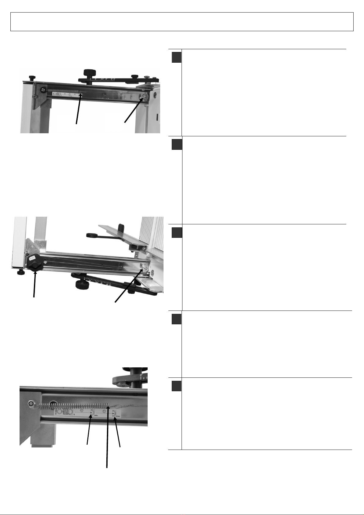
D
Draht ersetzen, Draht nachziehen
Das Gerät verfügt über eine Drahtvorratsrolle [26].
Bei einem Drahtriss den restlichen Draht entfernen.
Flügelgriff bei Spule [26] lösen, Draht wenig vorzie-
hen, eine kleine Schlaufe am Drahtende bilden, an
Zugfeder [27] einhängen, über die obere Drahtfüh-
rungsrolle [28] und die untere Drahtführungsrolle
[29] legen und durch Drehen an der Drahtspule [26]
ordentlich spannen. (Zugfederlänge = ca. 8 cm).
Flügelgriff festziehen.
F
Remplacer, retendre le filament
L’appareil est équipé d’un filamen d’alimentation rouleau
[22]. En cas de rupture du filament, enlevez ce qui reste
du filament. Dévissez légèrement la poignée à ailes située
sur le dévidoir [22], faites une petite boucle en extrémité
de filament, accrochez-la au ressort de rappel [23], pas-
sez au-dessus du rouleau guide de filament supérieur
[24], passez le filament sur le rouleau guide de filament
inférieur [25] et créez la tension adéquate en faisant tour-
ner le dévidoir de filament [22]. (Longueur du ressort de
rappel = env. 8 cm). Resserrez bien la vis papillon.
I
Sostituire il filo, tendere il filo
L’attrezzo dispone di una bobina di filo cavo [26]. In caso
di lacerazione del filo rimuovere il filo rimanente. Allentare
leggermente il manico ad alette vicino alla bobina [26], in
seguito formare un piccolo passante alla fine del filo, ag-
ganciarlo alla molla di trazione [27], adagiarlo sul rullo
conduttore del filo superiore [28] condurre il filo sopra il
rullo conduttore del filo inferiore [29] e tendere il filo per-
bene girando la bobina del filo [26]. (Lunghezza della mol-
la di trazione = ca. 8 cm). Stringere bene il manico ad
alette.
GB
Installing New Wire, Re-Tightening the Wire
The device has an wire suppy roll [26]. If the wire splits, re-
move the rest of it. Loosen the reel [26] using the butterfly
grip, form a small loop on the wire end, hang it on the top
pull-spring [27] and set the wire over the upper wire guide
roller [28]. Pull the wire up over the lower wire guide roller
[29] By turning the wire reel [26] tighten the wire properly
(pull spring length= 8cm). Tighten the butterfly grip.
CZ
Výměna, dotažení drátu
Zařízení disponuje zásobní rolí drátu [26]. V případě
přetržení drátu zbývající drát odstraňte. Povolte křídlovou
úchytku u cívky [26], trochu drát vytáhněte, vytvořte na konci
drátu malé očko, zavěste je na tažnou pružinu [27], veďte jej
přes horní váleček vedení drátu [28] a dolní váleček vedení
drátu [29] a řádnějej napněte otáčením cívky s drátem [29].
(délka tažné pružiny = cca 8 cm). Dotáhněte křídlové
držadlo.
26
27
28
29
Fig. 13
Fig. 14
Min. Max.
Fig. 11
27
12
Isoturbo
®
5305S-30
1903451 | 02-2014
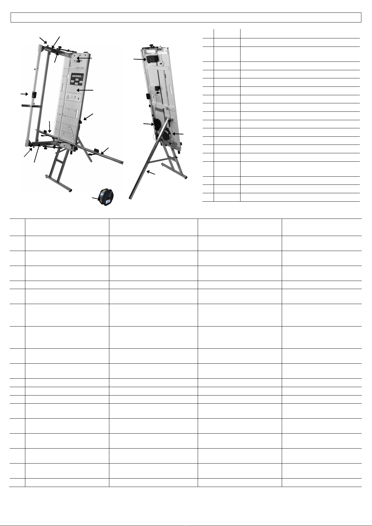
Ersatzteilliste / Nomenclature / Elenco parti di ricambio per modello / Spare parts list / Seznam dílů
Ersatzteile 5305S Mod. 2014
1
1900668
Auflageschiene links mit Skala und Verbreiterung
2
1900669
Auflageschiene rechts mit Skala und Verbreite-
rungen
3
1900655
Elektrogehäuse mit Dose
4
1900729
Freistellstütze
5
1903416
Holzbrett weiss mit Verstärkungsleisten
6
1900662
Kugelführung Oben mit Haltewinkel Zugfeder
7
1900663
Kugelführung Unten mit Haltewinkel
8
1900511
Massskala 100 cm
9
1900512
Massskala 50 cm
10
1900068
Netzkabel DE/EU Konturenstecker
10
1900067
Netzkabel CH mit Flachstecker
11
1900584
Reiter komplett
12
1900590
Schalter I-O-II mit Schutzhülle
13
1900671
Tiefenbegrenzerschraube M10x16 mit Druckfeder
14
1900664
Transformator 0-11-26V (230V) mit Sicherungs-
automat
15
1900652
Turboschaltergehäuse mit Drucktaster
16
1200018
Ersatzdrahtspule 20m
17
1903356
Zugfeder 50mm
Nomen lature 5305S Elen o parti di ri ambio per
modello
Spare parts list 5305S Seznam náhradní h dílů
5305S
1
Barre de support de gauche avec
graduation et extension
Scorrimento d‘appoggio sinistro con
scala graduata e estensione
Left Bearing Rail with Scale and
Extensions
Lišta uložení materiálu vlevo
s měřítkem a držáky rozšíření
2
Barre de support de gauche avec
graduation et extension
Scorrimento d’appoggio destro con
scala graduata e estensioni
Right Bearing rail with Scale and
Extensions
Lišta uložení materiálu vpravo
s měřítkem a držáky rozšíření
3
Cage électrique avec boîtier Carter elettrico con scatola Electrical Housing with Socket Skříň elektrické instalace se
zásuvkou
4
Béquilles Supporto per il montaggio libero Free-Standing Strut Volně nastavitelná podpěra
5
Plaque de bois à baguettes de ren-
fort
Tavola di legno con lista di rinforzo Wooden Board with Reinforcing
Rivets
Dřevěná deska se zesilovacími
lištami a kabelovým kanálem
6
Coulisseau à roulement à billes
supérieur avec cornière de main-
tien et ressort de rappel
Scorrimento per il cuscinetto a sfere
superiore con squadretta di suppor-
to molla a trazione
Ball Bearing Slider Top with Fixing
Bracket Tension Spring
Jezdec s kuličkovým ložiskem
horní s přídržným úhelníkem
tažná pružina
7
Coulisseau à roulement à billes
supérieur avec cornière de main-
tien
Scorrimento per il cuscinetto a sfere
inferiore con squadretta di supporto
Ball Bearing Slider Bottom with
Fixing Bracket
Jezdec s kuličkovým ložiskem
dolní s přídržným úhelníkem
8
Graduation 100 cm Scala graduata per misurazioni
100 cm
Graduated Scale 100 cm Měřítko 100 cm
9
Graduation 50 cm Scala graduata per misurazioni
50 cm
Graduated Scale 50 cm Měřítko 50 cm
10
Câble de réseau EU/DE Cavo elettrico EU Power Cord EU Síťový kabel EU
10
Câble de réseau CH Cavo elettrico Svizera Power Cord CH Síťový kabel CH
11
Cavalier complet Cavalletto completamente Locking tab Jezdec
12
Commutateur I-O-II avec en-
veloppe de protection
Interruttore I-O-II con custodia pro-
tettiva
Switch I-O-II with Protective Case Spínač I-O-II s ochranným
krytem
13
Vis de butée de profondeur
M10x16 avec ressort de pression
Vite di limitazione della profondità
M10x16 con molla di compressione
Depth Governing Screw M10x16
w/ Pressure Spring
Šroub omezení hloubky M10x16
s tlačnou pružinou
14
Transformateur 0-11-26V (230V)
avec automate de verrouillage
Trasformatore 0-11-26V (230V) con
macchinetta di sicurezza
Transformer 0-11-26V (230V) with
Auto Circuit Breaker
Transformátor 0-11-26 V (230 V)
s pojistkovým automatem
15
Boîtier de commutateur Turbo
avec bouton poussoir
Carter turbo per interruttori con inter-
ruttore da premere
Turbo-Switch Housing w/ Press
Button
Těleso turbospínače s tlačítkem
16
Bobine de filament de rechange
20m
Bobina di riserva per il filo di metallo
20m
Replacement Wire Reel 20m Náhradní drát 0 65 mm / 20 m
17
Ressort de traction 50mm Primavera 50 millimetri Spring 50 mm Natahovací pružina 50 mm
11
12
10
2,8
3
4
5
6
7
13
14
15
16
17
13
1
Other SPEWE Cutter manuals

SPEWE
SPEWE 890SL User manual

SPEWE
SPEWE 890SL User manual

SPEWE
SPEWE 1900M-24 User manual

SPEWE
SPEWE 112GT-28 User manual

SPEWE
SPEWE 791GT User manual

SPEWE
SPEWE 1900L-30 User manual

SPEWE
SPEWE 1900ML-30 04 Series User manual

SPEWE
SPEWE DT104-28 User manual

SPEWE
SPEWE DT127-30 User manual

SPEWE
SPEWE Isoturbo 6005L-30 Operation and maintenance manual


