Estate EST-EMTB275 User manual
INSTRUCTION MANUAL
E209
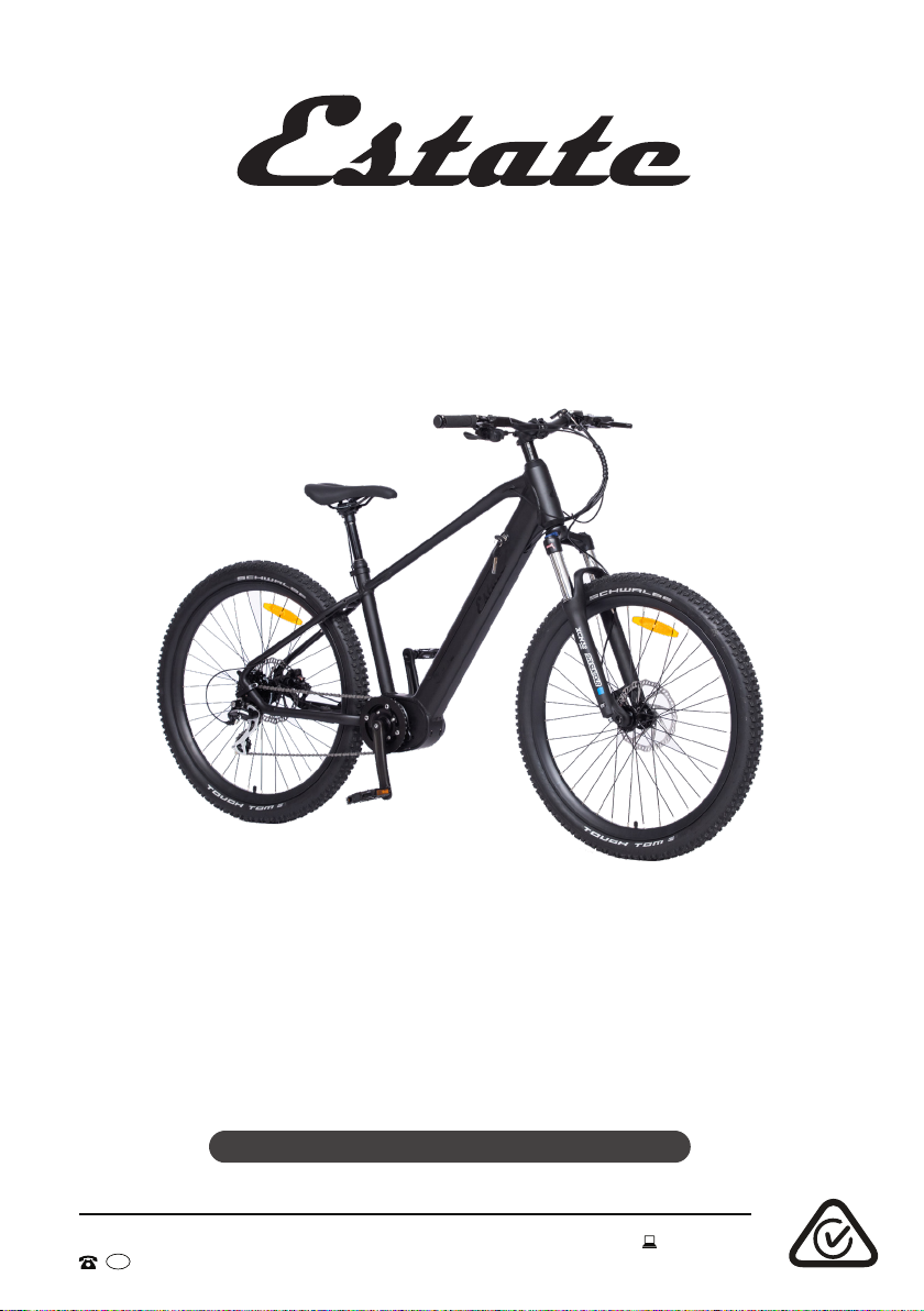
Electric Mountain Bicycle
Model Number EST-EMTB275
AUS
AFTER SALES SUPPORT
MODEL: EST-EMTB275 PRODUCT CODE: 706076 11/2021
1300 112 534
tempo.org/support

2
Welcome
Congratulations on choosing to buy an ESTATE product.
All products brought to you by ESTATE are manufactured to the highest
standards of performance and safety and, as part of our philosophy of
customer service and satisfaction, are backed by our comprehensive
1Year Warranty.
We hope you will enjoy using your purchase for many years to come.
2AUS
AFTER SALES SUPPORT
MODEL: EST-EMTB275 PRODUCT CODE: 706076 11/2021
1300 112 534
tempo.org/support

3
02 Welcome
04 Warranty Details
05 General Safety Instructions
08 Product Overview
09 Getting Started
10 Assembly
19 Battery Charging
21 Instructions
25 FAQs and Troubleshooting Guide
27 Other Useful Information
31 Repair and Refurbished Goods or Parts Notice
Contents
3
AUS
AFTER SALES SUPPORT
MODEL: EST-EMTB275 PRODUCT CODE: 706076 11/2021
1300 112 534
tempo.org/support

4
The product is guaranteed to be free from defects in workmanship and parts
for a period of 12 months from the date of purchase. Defects that occur within
this warranty period, under normal use and care, will be repaired, replaced
or refunded at our discretion. The benefits conferred by this warranty are
in addition to all rights and remedies in respect of the product that the
consumer has under the Competition and Consumer Act 2010 and similar
state and territory laws.
Our goods come with guarantees that cannot be excluded under the
Australian Consumer Law. You are entitled to a replacement or refund for a
major failure and to compensation for any other reasonably foreseeable loss
or damage. You are also entitled to have the goods repaired or replaced if
the goods fail to be of acceptable quality and the failure does not amount to
a major failure.
Warranty Details
REGISTER YOUR PURCHASE AT www.aldi.com.au/en/about-aldi/product-registration/ TO KEEP UP-TO-DATE WITH IMPORTANT PRODUCT INFORMATION
YEAR WARRANTY
1
4AUS
AFTER SALES SUPPORT
MODEL: EST-EMTB275 PRODUCT CODE: 706076 11/2021
1300 112 534
tempo.org/support
Electric Mountain Bicycle

5
General Safety Instructions
WARNING: Read and follow all safety warnings before riding!
• Local traffic laws: Some state and local traffic laws may require that your bicycle
be equipped with a warning device, such as a horn or bell and a light, if the bicycle
is to be ridden after dark. When you are riding on the road, make sure that you are
always visible to other vehicles. Please respect the road rules in all circumstances.
• Intended use: This bicycle should only be used for personal recreational
purposes, and not for commercial activities, trade or competition. Do not use this
bike for stunts. Do not use the bicycle for anything other than its intended purpose,
and only use it as described in this manual. Improper use may affect the warranty.
• Usage restrictions: This bicycle is not intended for use by persons (including
children) with reduced physical, sensory or mental capabilities, or lack of
experience and knowledge, unless they have been given supervision or instruction
concerning use of the bicycle by a person responsible for their safety.
• Protective equipment: Always wear proper protective equipment, such as an
Australian standards-approved helmet, elbow pads, knee pads, long sleeve shirt,
gloves, long pants.
• Wet weather warning: Slow down your speed when riding in rainy and snowy
conditions and in slippery areas. Increase your braking distance to ensure safety.
Use the rear brake lever FIRST, then the front brake lever.
• Always double-check your bike before riding it (tighten the handlebars and
stem, check the saddle, wheels and brakes, etc.). We strongly recommend that
significant mechanical repairs are carried out by a skilled bicycle mechanic.
• Height adjustment: Adjust the seat height and handlebar height appropriately:
the rider must be able to straddle the bicycle with at least 2.5 cm clearance above
the horizontal bar when standing. Please refer to the assembly section for details.
• Check the tyre pressure: The tyre pressure range of this bicycle is 160–350 kPa
(23-50 psi), which is marked on the tyre. Please ensure that the tyre pressure is
within this range to avoid accidents (1 psi = 6.895 kPa).
IMPORTANT SAFETY INSTRUCTIONS
READ CAREFULLY AND KEEP FOR FUTURE REFERENCE
Read this manual thoroughly before first use, even if you are familiar with this type of
product. The safety precautions enclosed herein reduce the risk of injury and product
damage. Keep the manual in a safe place for future reference, along with the completed
warranty card, purchase receipt and carton. If applicable, pass these instructions on to
the next owner of the bicycle.
NOTE: Throughout the instructions, this product may be referred to as electric
mountain bike, e-mountain bike, bicycle or simply as bike.
Always follow basic safety precautions and accident prevention measures when
riding a bike (or e-bike), including the following:
5
AUS
AFTER SALES SUPPORT
MODEL: EST-EMTB275 PRODUCT CODE: 706076 11/2021
1300 112 534
tempo.org/support
Other manuals for EST-EMTB275
1
Table of contents
Other Estate Bicycle manuals

Estate
Estate EST-EFLDBIKE1 User manual

Estate
Estate EST-EMTB275 User manual

Estate
Estate City ESTC27M User manual

Estate
Estate City ESTC27U User manual

Estate
Estate EST-MTB29 User manual

Estate
Estate FOLD EST-EFLDBIKE User manual

Estate
Estate City ESTC27M1 2023 User manual

Estate
Estate City ESTC27U1 2023 User manual

Estate
Estate EST-EFLDBIKE User manual

Estate
Estate EST-MTB24G User manual


