5
2 Handling/Transportation
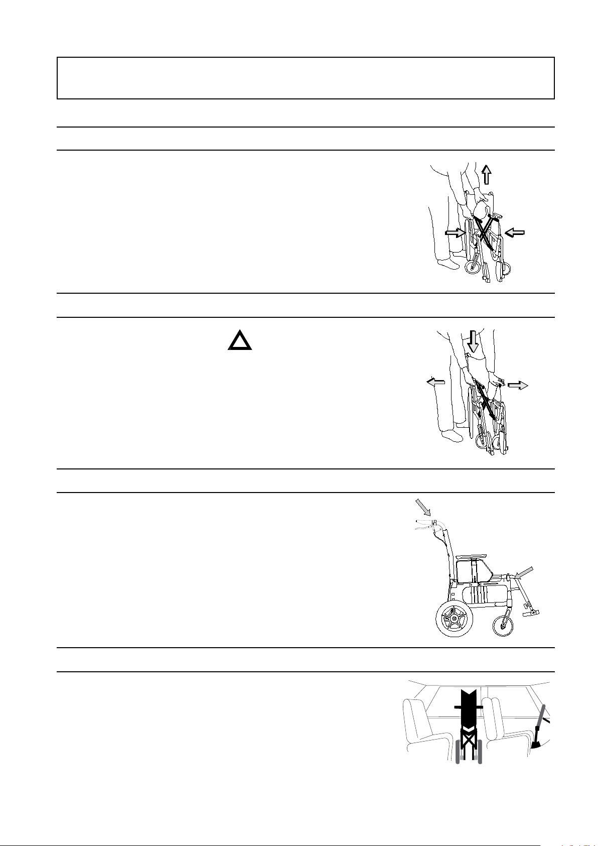
2:5 Securing
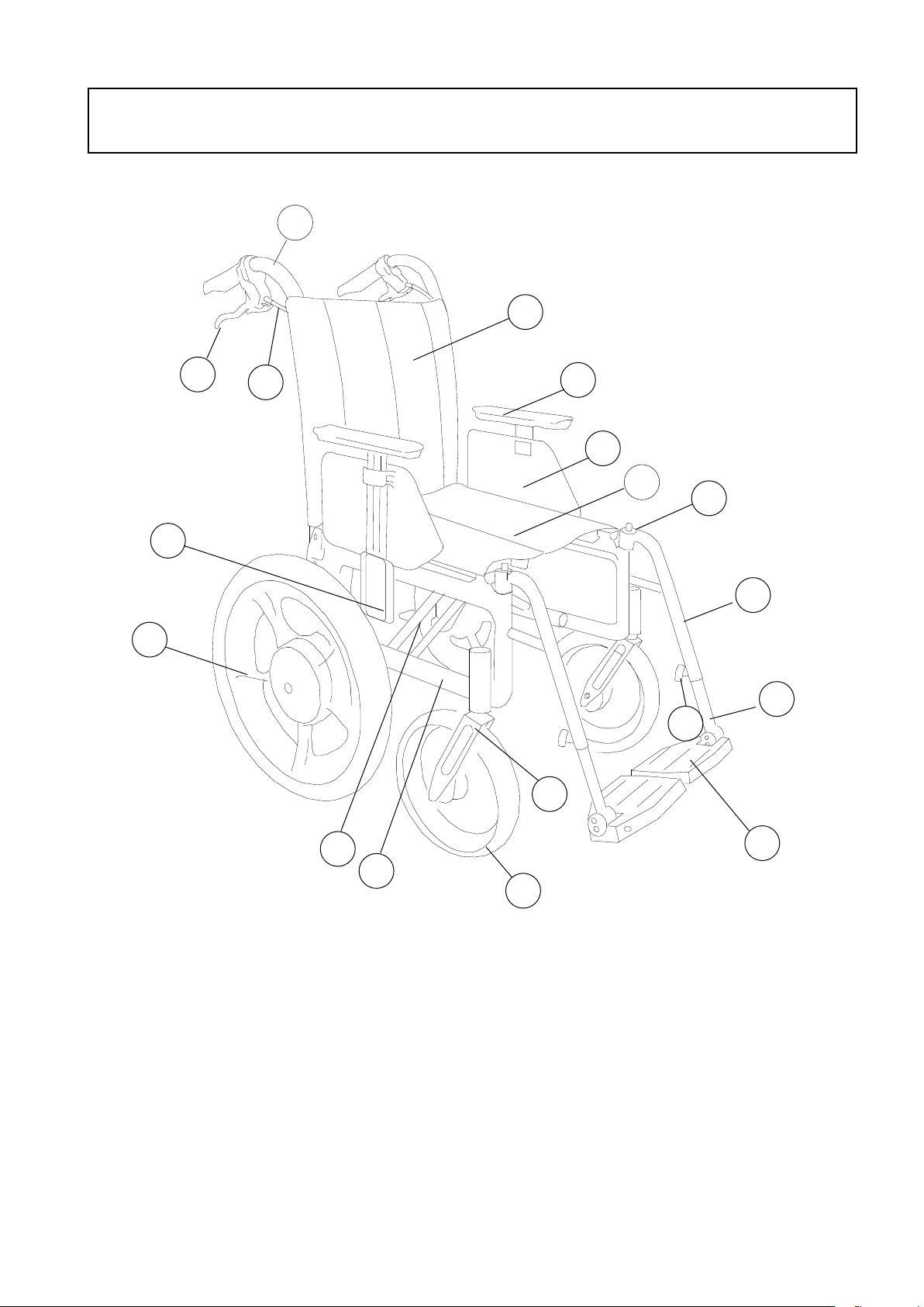
2:6 Seat belt
The wheelchair must be secured as
follows, the straps must not be put
through the wheels or around the back
tubes.
If the wheelchair is used as a seat for
travel, Etac recommends that the user
uses the 3-point belt that is fitted in
the vehicle.
It is important that the 3-point belt is
fitted correctly, as in the illustrations:
2:7 Recommendations
2:8 Warning
- The wheelchair’s positioning
belt is not sufficient to prevent
the user from being thrown out
of the wheelchair in the event of
sudden braking.
- The restraining device must not
be put through the wheels or
around the back tubes.
- Options/accessories that can be
removed without tools, such as
trays, shall be removed and
secured/positioned so that they
do not fly around inside the
vehicle in the event of a collision.
Etac recommends in the following
order:
1) The user transfers to a seat in the
vehicle and uses the vehicle’s 3-point
belt while travelling. The wheelchair
is then placed in the boot or safely
in the back seat so that it cannot
overturn or roll.
2) The wheelchair is secured facing
forwards in the vehicle as per this
manual, the user uses a separate
3-point belt that is secured in the
vehicle. This is the way in which the
wheelchair is tested and approved
according to the ISO-standard for
crash testing of wheelchairs in vehicles.
3) According to directive 2001/85/
EC, appendix VII, point 3.8.3. there
are specially marked wheelchair
locations in vehicles that permit
transport with a wheelchair facing in
the direction of travel. If this means
of travel is used, the user/carer must
be aware while travelling, prepared
for sudden movements and have the
capacity to maintain a safe sitting
position throughout the entire journey.
The user’s disabilities must not be of
such an extent that he/she is not able
to hold onto the handles fitted in the
vehicle when there are changes of
speed or direction.
In conjunction with points 2 and 3:
- a 25668 positioning belt shall
be used
- a correctly adjusted headrest shall
be used
- the backrest shall be level with or
above the user’s shoulders
- the parking brake shall be used
- the anti-tips shall be lowered
- backrest brace shall be used
- If the wheelchair has been
involved in a collision in a motor
vehicle, it should be inspected at
a Technical Aids Centre or by
Etac before being used again.