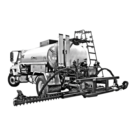
Etnyre Black-Topper BT-1 Distributors 2008 Technical manual

M-131-21
Black-Topper®
BT-1 Distributors
2008 or newer
Updates &
Service Material
October 2021

M-131-21
Black-Topper®ASPHALT DISTRIBUTOR
Updates & Service Material
HOW TO ORDER PARTS
To assure prompt delivery when ordering parts, please furnish the following information:
1) Complete name and address of consignee. 2) Method of shipment preferred. 3) Is ship-
ment to be prep aid or collect? 4) Serial numbers of units to which parts apply. 5) Com-
plete part numbers and descriptions. 6) Any special instructions.
Specify unit serial number when ordering parts!
WARRANTY
E. D. Etnyre & Co. warrants to the original Purchaser, its new product to be free from defects in
material and workmanship for a period of twelve (12) months after date of delivery to original
Purchaser. The obligation of the Company is limited to repairing or replacing any defective part
returned to the Company and will not be responsible for consequential damages or any further loss
by reason of such defect.
The company excludes all implied warranties of merchantability and tness for a particular
purpose. There are no warranties, express or implied, which extend beyond the description of
the goods contained in this contract.
This warranty does not obligate the Company to bear the cost of machine transportation in connection
with the replacement or repair of defective parts, nor does it guarantee repair or replacement of any
parts on which unauthorized repairs or alterations have been made or for components not manufac-
tured by the Company except to the extent of the warranty given by the original Manufacturer.
This warranty does not apply to:
(1) Normal start-up services, normal maintenance services or adjustments usually performed
by the selling dealer, factory service representative or customer personnel.
(2) Any product manufactured by E. D. Etnyre & Co. purchased or subjected to rental use.
(3) Any product or part thereof which shows improper operation, improper maintenance, abuse,
neglect,damageormodicationaftershipmentfromfactory.
(4) Any product or part thereof damaged or lost in shipment. Inspection for damage should be
made before acceptance or signing any delivery documents releasing responsibility of the
delivering carrier.
This warranty and foregoing obligations are in lieu of all other obligations and liabilities including
negligence and all warranties of merchantability or otherwise, express or implied in fact or by law.
E. D. ETNYRE & CO., Oregon, Illinois 61061-9778
1333 South Daysville Road Phone: 800-995-2116 Fax: 800-521-1107
www.etnyre.com [email protected]
October, 2021
1

2

Table Of Contents
HOW TO ORDER PARTS ................................................. 1
WARRANTY ...................................................................... 1
SERVICE & ADJUSTMENT PROCEDURES
Radar Calibration for DC-2 & S2X Computers .................. 4
Radar Calibration for BT-1 Computers...............................4
Servicing Asphalt Pump Shaft Packing ............................. 5
Servicing 4-Way Valve Packing..........................................5
Servicing Tank Suction Valves & Gaskets ......................... 6
Servicing Spraybar Swivel Joints.......................................6
Adjusting Pump Neutral on 42 & 90 Series Pumps........... 7
Testing EDC Threshold on 42 & 90 Series Pumps...............7
Aventics Valve Diagnostics................................................ 8
Meaning of the diagnostics LED'S...............................8-9
Testing GPM with Photo Tach...........................................10
Testing Electronic Tilt Switches........................................10
COMPONENT ILLUSTRATED BREAKDOWN INFO
Hydrostatic Drive System - PTO Driven - 42 Series........ 11
Planetary Gearbox - Asphalt Pump ................................. 12
Asphalt Pump Assembly.................................................. 13
4-Way Valve Assembly and Controls............................... 14
Installing )6445090) Shaft Coupling between
Asphalt Pump and Gearbox.......................................... 15
Timing Adjustment of Actuators ....................................... 16
4-Way Flow Positions ...................................................... 17
Front Suction Valve Assembly..........................................18
Rear Suction Valve Assembly...........................................19
Ball Joint Tightening and Locking.....................................20
Swivel Joint......................................................................21
Solenoid Valves for Multifold Spraybars...........................22
Hydraulic Manifold Asm - Variable Width Spray Bar.........23
4 Station Manifold Assembly............................................24
4 Station Heavy Duty Hydraulic Manifold.........................25
6 Station Manifold Assembly............................................26
Heavy Duty Bar Raise......................................................27
Bleeding Heavy Duty Spraybar Lift Cylinders..................28
Air Suppy - Standard Bar - 1 Ft. Increments....................29
Tack Coat Valve - Variable Width Spray Bar....................30
Air System - 4 Ft. Wing - Variable Width Spray Bar.........31
Air System - 8 Ft Bar - Variable Width Spray Bar.................32
QUICK REFERENCE SCHEMATICS
Schematic 9307612......................................................... 33
Schematic 9307613......................................................... 34
Schematic 9307614......................................................... 35
Schematic 9307615......................................................... 36
Schematic 9307616......................................................... 37
Standard Bar w/ 1FT Controls - Master Spray
Switch 9307468............................................................ 38
1 FT Control Switch - Standard Bar with
1 FT Controls - 9307469............................................... 39
Variable Width Distributor with Aventics Valves -
1 FT Control Switch - 9307470..................................... 40
Variable Width Distributor with Aventics Valves -
Master Spray Switch - 9307471 ................................... 41
Distributor Communication Highway - 9307472 .............. 42
Function Control Knob - (BT-1 2008) - 9307473 ............. 43
Function Control Knob - (BT-1 2010) - 9307474..............44
Function Keypad - BT-1 (2017 & Newer) - 9307475............45
Switches @ Cab Control Panel - 9307476........................46
Switches @ Rear Control Panel - 9307477.......................47
3

4
SERVICE & ADJUSTMENT PROCEDURES
Radar Calibration for DC-2 & S2X Computers:
1. Mark off a 1,000 ft course for testing and calibrating.
2. Inspect the radar for angle, clear view to the ground,
cleanliness of lens, moisture free.
3. Turn the Pump Control switch at rear panel to Front
Pump control.
4. Disabletheipvalveson1ftofspraybarattheend
of the main bar.
5. Turnoncontrolboxpowerwithdisplayfunctioning.
6. Activate the l foot switch that correlates to the bar
youdisabled(allothersoff).
7. AdjusttheApplicationRateallthewaydowntoits
lowestsetting(.005).
8. ChangethedisplaytoshowFeetTravelledandreset
tozero(0).
9. Lineupwithyourstartline.
10.Asyoustarttodrivethetruck(slowandsteady),turn
ontheMasterSprayswitchtoinitiatethespraymode
andcountfeet(anyerrorsthatpopuponscreen
during the test will effect the feet counted). Maintain
aslowandsteadyspeed,donotshiftgearsetc.
11.TurnoffMasterSprayswitchattheendofmeasured
courseandverifydistancecounted.Distancecounted
shouldbeclosetothemeasureddistance(3ft+or-).
If not,
a.Adjust radar angle. Down equals less feet, Up
equals more feet. or,
b.Adjust Speed Cal factor in Computer Set Up,
butonlyifallattemptstocorrectbychangingthe
radaranglefail.Shortonfeet,adjust(UP).Long
onfeet,adjust(Down).One(1)digitequals10
feet using 1,000 ft. course. Make sure to save
adjusted values.
12.Retest distance and angle or calibration until the
distributer computes the correct distance.
13.Enableipvalvesonspraybarbeforespraying
asphalt.
14.AdjustApplicationRatetopropersprayrate.
Radar Calibration for BT-1 Computers
1. Mark off a 300 ft course for testing and calibrating.
2. Inspect the radar for angle, clear view to the ground,
cleanliness of lens, moisture free.
3. Turn Function knob at rear control box to (LOAD).
4. Turn on control box power with display functioning.
5. Turn off all 1ft control switches.
6. Line up with your start line.
7. Change the display to show Feet Travelled and reset
to zero (0).
8. As you start to drive the truck (slow and steady) turn
on the Master Spray switch to initiate the spray mode
and count feet.
9. Turn off the Master Spray switch at the end of
the measured course and verify the distance counted.
Distance counted should be close to the measured
distance (1 ft + or -). If not,
10.Enter Computer Set Up Screens to Distance Calibration
screen.
11.Line up with your start line.
12. As you start to drive the truck (slow and steady),
press the Pump Strut button to strut the calibration
process. At the end of the measured course, press
the Pump Start button to end the process.
13.Shut off the power to the control box to save the
calibration.
14.Line up with your start line.
15.Change the display to show Feet Travelled and reset
o zero (0).
16.As you start to drive the truck (slow and steady) turn
on the Master Spray switch to initiate the spray mode
and count feet. Turn off the Master Spray switch
at the end of the measured course and verify distance
counted. The distance counted should be close to the
measured distance (1 ft +or-). Re-calibrate if needed.

5
Servicing Asphalt Pump Shaft Packing
*Note: Packing on this application, is allowed to
seep which lubricates the Pump Shaft. Tightening it
to the point of it not seeping anymore, will cause the
packing to overheat and eventually leak worse.
(Do Not Overtighten)
1. Remove the shield protecting the pump shaft drive
coupling.
2. Removethe(2)Locknutssecuringthe2piece
packinggland.(SometimesifDriveCouplingis
installed too close to the Asphalt Pump asm there is
not enough room to remove the lock nuts causing the
removalofdrivecouplingtogainaccesstore-pack
the pump shaft).
3. RemovePumpShaftDriveCoupling(ifNecessary).
4. Remove the lock nuts, locking plates and packing
glands to allow access to remove packing.
5. RemovePacking(preferred)toinstallnew.
6. Soak new packing in motor oil.
7. Installnewpacking,rotatingjointsasyouinstall
piecesanditshouldhold(4-5)piecesofpacking
# 6600310.
8. Install Packing Glands and secure with locking plates
andlocknuts(Tightennutsevenlytokeepthe
Glandsinlinewiththeshaft.(DoNotOvertighten)
9. Install the Coupling, if it was removed (*Note see
torque spec. instructions in component illustrated
breakdown section.)
10.Installshield.(Torquegearboxmountingboltsto
25 ft/lbs).
11.Re-tightenifneeded.(*Note See an illustrated break
down of Asphalt Pump & shaft in component
Illustrated breakdown section).
Servicing 4-way Valve Packing
1. Makesure4-wayValvekeywayisinthe(12o’clock)
positionbeforeremovinganything.
2. RemoveRotaryActuatorfor(BarCirc)theone
mountedtothebracket@rearlocation(Makenoteof
mounting location or take pictures to insure
installation is correct).
3. Removefront(Spray)RotaryActuatorfromshaftof
4-wayValve.
4. Loosenandremove(2)Nuts&washersecuringthe
spring&packing.
5. Removethepackingthatisremaining(Replace
packing-DoNotAddtowhatisleft).
6. Soaknewpackinginmotoroil,Install(3)newpieces
ofPacking#3340029,rotatingthejointsastheyare
installed.Installspring,#3341464(ifnewisneeded).
Installwasher#0197070(1-3/8)ifnotpreviously
installed to complete the installation and update the
4-wayvalvetocurrentconguration.
7. Installrstnutandtightenuptighttothehousing,
then back off ¼ turn. This will allow valve to turn,
butnotMove(In&Out)whichwillallowoilto
owthewrongdirectionandby-passvalvecausing
ittospraylightbyreturningmaterialtotankorow
intothebarwhenyoudonotwantitthere.
8. InstalltheSecondnutandsecuretherst(lock
togethertightly)Makesureyoucanstillrotateand
turn4-waywithwrenchesbeforeinstallingactuators.
9. Installthekeyandcoupling(makesuretheyttight)
couldaffecttheaccuracyofthetiming.
10.InstallSprayActuatorinoriginalposition.
11.InstallandinsertBarCircActuatorintoSpray
Actuator, should be in the same position of
orientationastheSprayActuatorandsecureand
torqueto(20ft/lbs)withmountingboltstothe
bracket.(GotoInstallationofActuatorspageifneeded)
12.CheckTimingof4-wayValve(GotoAdjusting
4-waytimingprocedureifadjustmentifneeded)
13.Test4-wayoperations/Load(12o’clock)BarCirc
(9o’clock)&Spray(6o’clock)thelessmarginof
Timingerrors,thebetterthe4-wayValveand
distributor will perform.
(*Note See an illustrated break down of 4-way Valve &
Actuators in component Illustrated breakdown section)
SERVICE & ADJUSTMENT PROCEDURES

Servicing Tank Suction Valves & Gaskets
1. Emptytankof(all)materialinside(elevatefrontof
truckifpossibletomakesureyougetitasemptyas
possible)
2. ElevateRearoftruckifpossibleasasafetymeasure
(anyleft-overmaterialwillowtofrontoftank)
3. OpenFill-linecap/ActivateandopenTankValve
andmakesureTankisemptybeforeremovingValve
4 OpenStrainerBoxlidandinspectvalveforother
issues(BrokenSpring/missingsnapringetc)
5. ActivateandopenTankValvebeforeremovingthe
(8)boltsattachingtheTankValvetotheStrainerBox
6. RemoveTankValveslightlyabout2inches/then
allowTankValvetoclosereleasingspringtension.
7. Marktoidentify&removeairlines,thenyoucan
remove and relocate valve to workspace.
8. Clamp valve in vise without crushing or imprinting
the gasket sealing surfaces or air chamber asm.
9. Testwithshopairorothersource(A)istheopen
sideclosesttothevalve(B)isclosed@sightglass.
10.IfTankFlangegasketistheonlyrepairneeded,
replacegasket(Greenportiontowardtank)and
proceedto#(19).
11.If Air chamber or spring require service proceed with
the following.
12.Removecapwithsightglassattached.Laypartsout
intheordertheyareremoved.
13.Loosenlocknutinside(slowly)springtensionwill
be relieved as it is removed.
14.Removeshaftandspring/payattentiontowasher
in behind spring and note where it belongs.
15.Dis-assembleairchamberpiecebypieceandreplace
O-rings,Packing&Sealsandre-assemble.
16.Re-insertshaftwithspring&washer,placevalve
nosedown/gasket@andontheoor.
17.Pressdownwardonvalveandcompressslightlyto
get lock nut started inside air chamber asm.
18.Tighten down lock nut compressing the spring and
/Inspect&cleansightglassonendcap,applythread
sealantifremoved.(Thiswillallowavisual
indicationofTankSuctionValveposition&
operation) Install Cap.
19.Re-installvalveintoviseandbenchtesttheTank
valve one more time before installing on Distributor.
20.PlaceValveasmintoStrainerBox/Installairlines
andactivateandopenTankValveasm.
21.Install510Loctitegasketeliminatoronangeand
install valve with mounting bolts.
22.Operatevalvetoopenandclosedseveraltimesto
imprintthenewgasketontankange.
23.Check and clean Strainer.
24.Check Packing seal on Strainer Lid (replace if
needed) Install and secure Strainer Lid.
25.Filldistributorandsafelytestforleaks
(*Note See an illustrated breakdown of the Tank Suction
Valves in component Illustrated breakdown section)
Servicing Spraybar Swivel Joints
*Note: Swivel joint assemblies tend to leak past the
O-ring between the 2 main component parts, changing
the mounting gaskets or tightening the nuts that secure
it to the plumbing will not x the leak.
1. Determine if the joint is able to be disassembled and
servicedorshouldbereplaced(Ifthejoint
moves too much side to side or has broken studs /
replace swivel joint).
2. MakesurethatSpraybarissuckedbackandlittleor
nomaterialisleftintheCirculatingSystem.
3. SupporttheportionofSpraybarorCirculation
Plumbing needing to be disassembled.
4. Removenuts&lockwashersthatattachthe
assembletothebarorcirculatingpipes(notethe
Grease zerk position, and which side of joint pivots
tomakesureyouinstallitthesameway)
5. SeparateandremoveSwivelJoint(Makesure
internal plumbing is intact and rigid. 3x3 Standard
Barusesapipeslipjointmethod/BigBar&
VariableWidthbars,useacouplingw/O-ringsto
getapositivesealatallconnections.OnVariable
Widthbarsthecirculatingpipemayhavetobe
removed@(2)jointstogetitremovedfromunit).
6. Ifreplacementisyourepairmethod,makesureto
clean all gasket surfaces, check internal plumbing
andreplaceO-ringsifneeded/ifservicingjoint(Go
to step # 8).
7. Install Joint with new gaskets, position grease zert
asnotedearlier,Donotovertightennutstheyare
attached to a weld on stud.
8. TodisassembleSwivelJointyouwillneedto1st
cleanthepart.(Hardmaterialwillbemuchharder
to disassemble).
6
SERVICE & ADJUSTMENT PROCEDURES

9. RemoveGreasezert&adaptertogainaccesstothe
(47)ballbearings,holdingthejointtogether.
10.Rotate the movable ½ of joint and collect the ball
bearingsthatfallout(youmayhavetocreatively
compress the joint together to disassemble).
11.SeparatejointtogainaccesstoO-ringinside(inspect
joint and ball bearing grooves to make sure that it is
not worn too much to rebuild).
12.LubricateandinstallnewO-ring/rotateandreinstall
(47)ballbearings/installadapterandgreasezert
/rotateandgreasefully(400degHightemp)before
installation on unit.
13.Clean all gasket surfaces, check internal plumbing,
andreplaceO-ringsifneeded/Returntostep(7)to
complete the install.
(*Note See an illustrated break down of swivel joint in
component Illustrated breakdown section)
Adjusting Pump Neutral on 42 & 90 Series Pumps
1. Pump neutral may need to be adjusted, if the
Hydraulic Motor turning the Asphalt Pump turns
when Etnyre Control system is turned (Off} or is
operated in manual with Rear Pump Control
turned all the way CCW to (Off}. Adjusting is
better with 2 people:1 adjusting and 1 watching
Asphalt Pump Shaft rotation at the rear of
Distributor Truck.
2. Locate adjustment and gather tools to make
adjustment (be careful @ all times Due to live
PTO operation on the pump system).
3. Direction of adjusting neutral screw varies
depending on style and location of Hydrostatic
pump, (normal and correct direction of shaft
rotation is CCW standing @ the rear bumper
looking forward). Loosen jam nut while holding
the allen head adjustment screw, turn screw
slowly in CCW direction, if the pump shaft
speeds up, you are turning it the wrong direction,
turn it only till the pump shaft quits turning.
4. Rev up the engine and verify that pump shaft
does not try to turn, a slight adjustment may be
necessary if it does.
5. Onceyouaresatisedwiththeneutraladjustment,
it is recommended to test the (EDC} current to
the Hydrostatic Pump Controller, or (EDC} once
the value is determined, set the DC/Ma value in
the Computer set-up of the Etnyre Control
system under EDC Threshold.
42 Series
Testing EDC Threshold
90 Series
Testing EDC Threshold on 42 & 90 Series Pumps
*Note: EDC pump current in (DC/Milliamp’s) is
measured to accurately set the current needed to
initially rotate and turn the Asphalt Pump shaft, this
is installed and entered into the computer setup screen
Threshold MA =) once it is measured, current range
should be: (10.0 -19.0 Dc/ma)
1. Install Service adapter # 3371084 @ pump connector
(easiestandfastest)orinstallyourmeterinseries
acrossanyconnectionthatyouwillhavetodismantle
to connect to the power wire between rear control
boxpumpactivationrelayandthepumpEDC
connector.
2. Onceconnected,operatepumpsystemin(LOAD)
on manual mode with Pump Control pot turned full
ccwor(Off)metershouldread(6.0-9.0Dc/ma)
3. RotatePot(cw)toincreasecurrentandstopwhen
theAsphaltPumpshaftjuststartstoturn(ccw).
4. Thecurrentmeasuredonyourmeteratthispointis
yourEDCThresholdreading,shouldbebetween
(10.0&19.0Dc/ma)
5. If the EDC Threshold is not within those #s, or is
turning(CW)foranyreason,thepumpneutralmay
havetobeadjustedtoproperlysettheEDC
Threshold.RefertoAdjustingPumpNeutral
procedure section of this manual.
7
SERVICE & ADJUSTMENT PROCEDURES

RIGHT SIDE VALVE BANK
-SET S2 TO 0
-SET S3 TO 3
SEE S1 FOR DIP SWITCHES
-DIP SWITCH 3 SET TO ON
-DIP SWITCH 1, 2 AND 4 SET TO OPEN
OPEN
S1
S2
S3
AIR VALVE CAN MODULE
ON
LEFT SIDE VALVE BANK
-SET S2 TO 0
-SET S3 TO 2
SEE S1 FOR DIP SWITCHES
-DIP SWITCH 3 SET TO ON
-DIP SWITCH 1, 2 AND 4 SET TO OPEN
OPEN
S1
S2
S3
AIR VALVE CAN MODULE
ON
Aventics Valve Diagnostics
Meaning of the diagnostic LED’S
Designation Color State Meaning
UL(14) Green Illuminated Supplyvoltageisgreaterthan(18VDC)
Red Flashes Supplyvoltageislessthan(18VDC)andgreater
than(10VDC)
Red Illuminated Supplyvoltageislessthan(10VDC)
Green/Red Off Supplyvoltagetoolowormissing
UA(15) Green Illuminated Supplyvoltageisgreaterthan(21.6VDC)
Red Flashes Supplyvoltageislessthan(21.6VDC)andgreater
than(10VDC)
Red Illuminated Supplyvoltageislessthan(10VDC)
Green/Red Off Supplyvoltageistoolowormissing
8
SERVICE & ADJUSTMENT PROCEDURES

Aventics Valve Diagnostics Cont'd
Meaning of the diagnostic LED’S
Designation Color State Meaning
IO/Diag(16) Green Illuminated Thecongurationis(OK)andthebackplane
communicationis(OK)
Green Flashes IncorrectCANaddress
Red Illuminated Diagnostic message from module present
Red Flashes Congurationorbackplanecommunicationerror
Run(17) Green Illuminated Operationdisplay,Moduleisinthe(Operational)State
Green Flashes(Slow) Moduleisin(Pre-Operational)State-Slaveis
waitingforstartsignalfromCANMaster
Green Flashes(Once) Moduleisinthe(Stopped)State
Green Off Moduleisinthe(Initializing)State
Error(18) Red Illuminated Moduleisinthe(BUSOff/NonActive)State
Red Flashes(Once) Moduleisinthe(ErrorPassive)State-atleastone
error counter has reached/exceeded limit.
Red Flashes(Twice) Moduleisinthe(ErrorControlEvent)State
Monitoring error has occurred
Red Flashes(Three) Moduleisin(SyncError)State-Transmission
interrupted or out of prescribed allowance
None(19) None None Notassigned
9
SERVICE & ADJUSTMENT PROCEDURES

10
Testing GPM with Photo Tach
1. MakesureDistributorsengineisleft(Off)untilready
to start.
2. First thing would be to clean a spot off on the Asphalt
Pump drive shaft or drive coupling to install a
reectivestripforyouphototachtoreadtheRPM
of the pump shaft.
3. Installareectivestriponshaft.
4. StarttheDistributor&activatethepumpandallow
the pump shaft to turn @ a random speed, take a
phototachreadingofRPM(Testingformula:
RPM X 0.61 = GPM).
5. Test@variousspeedsandcheckaccuracy.
6. Ifresultsdonotmatch,(checkthepumppulses#in
theComputersetupscreen-MotorPul/Rev=
Newerdistributors:42Seriespump=43pulses,
90 Series pump = 46 pulses.
(Ifthehydraulicmotorhasbeenalteredformorespeed
ormoretorque)thosenumbersabovemaydiffer/
pulsesmayhavetobeadjustedtogetthecorrect
GPM reading)
[ GPM Test Formula – RPM X 0.61 = GPM ]
Testing Electronic Tilt Switches
1. Using Test adapter # 3371144, eliminates probing
wiresandplugsdirectlyintotheendoftheHarness
andisusedwithanydigitalvoltohmmeter.
2. Terminal # 3 should have 12vdc using ground from
#1.
3. Terminal # 1 is the source ground to the sensor.
4. Terminal # 6 is the ground returning from the Tilt
SwitchtotheSprayDelayrelayonW1ormac
ValvesforW2,W3andMarker(ifequipped)and
activatingthespraybarsection.
5. If adapter is plugged into harness and 12vdc on red
wire @ # 3, bar turns on / replace Tilt Switch.
6. If adapter is plugged into harness and 12vdc on red
wire @ #3, bar does not turn on / problem in
ground wire inside harness from terminal # 6, /
check and repair wiring.
7. If adapter is plugged into harness and no 12vdc /
problem in wiring harness either 12vdc, ground or both
are lost. / Check and repair wiring.
LedLightStatusonSensor:
GreenLight:UnithasreceivedpowerandisOn
RedLight:Whentheredlightisonsolid,OperatingProperly
Whenthelightisblinking,aFaultCodehas
been detected.
SERVICE & ADJUSTMENT PROCEDURES

11
COMPONENT ILLUSTRATED BREAKDOWN INFO
Return
From
Pump
To
Hydraulic
Tank
OPTIONAL
Auxilary Pump
Suction
Charge Pump
Suction
B
A
Left Hand Pump Shown
For RH Pump - Ref. 33 - Main Pump:
"B" (high pressure port) is connected to the "A" port of the moto
r
"A" (low pressure port) is connected to the "B" port of the motor
Asphalt
Pump
To Solenoid
Valves
Low Press
High Press
Return From
Solenoid Valves
Case Drain
To
Rear Control Box
Hydrostatic Drive System - PTO Driven - 42 Series

12
Planetary Gearbox - Asphalt Pump
*Service Item
Fill Level
85W90 Gear Oil
COMPONENT ILLUSTRATED BREAKDOWN INFO

13
COMPONENT ILLUSTRATED BREAKDOWN INFO
Asphalt Pump Assembly
13
(4) Dots
this side
(2) Dots
this side
(1) Dot
this side
(3) Dots
this side
Front Face Plate
for Heated Pump
End Plate
for Heated
Pump

14
To "A" Port Of "Spray" MAC Valve
Torque to 20 Ft/Lb
Spray
Actuator
Bar Circ
Actuator
To "B" Port Of "Spray" MAC Valve
T
o "A" Port Of 4-Way Valve
To "B" Port Of 4-Way Valve
4 Way Valve Asm and Controls
COMPONENT ILLUSTRATED BREAKDOWN INFO

15
COMPONENT ILLUSTRATED BREAKDOWN INFO
Installing (6445090) Shaft Coupling between Asphalt Pump and Gearbox
1. Coatallcouplingboltswithanti-seizebeforeinstalling.
2. Aligntheasphaltpumpshaftkeywaytotopdeadcenter.
3. Installshaftkeyinasphaltpumpshaft.
4. Slide coupling onto asphalt pump shaft. The asphalt
shaftandcouplingengagementshouldbeamini-
mumof3.03inches.Note:Itworksbesttoloosen
the screws in the coupling just enough for the
coupling to just slide on to the shaft.
5. Withthekeyinstalledinthegearboxshaft,insert
the gearbox shaft into the coupling until the gearbox
mountingangermlytouchestheasphaltpump
faceplate. Shaft engagement in step three should
bemaintained.Note:Againitworksbesttoloosen
the screws in the coupling just enough for the
gearbox shaft to be inserted while maintaining
thesametbetweentheasphaltpumpshaftandthe
coupling.
6. Align the gearbox for proper port location and so
that
two of the mounting holes align with both tapped
holes in the asphalt pump faceplate. Install two 5/16"
grade 8 bolts into the tapped holes in the faceplate.
Note: Do not tighten the mounting bolts but install
them so that they support the weight of the gearbox
and maintain contact between the gearbox and the
pump faceplate.
7. The gap between the halves of the coupling should
be equal. To maintain the desired gap, 1/32" shim
stockcanbeinsertedbytherstbolttightened
and then can be pulled out when the opposite side is
tightened.
8. Withthesocketheadcapscrewsatthetopdead
center, start the tightening sequence at 66 ft/lbs.
Note: When facing the asphalt pump there are six
rows of screws the rst being closest to the gearbox.
The tightening sequence is to start in row six (at the
top left) then to row one (the lower right then to the
lower left) and then to row six (the upper right). Use
this same pattern for rows ve and two and also rows
four and three.
9. Repeat the tightening sequence in step seven at
133 ft/lbs.
10.Repeatstepeightforverication.
11.Tighten gear box mounting bolts to 25 ft/lbs.
Correct installation can be verified when
hydraulically driving the asphalt pump. If the
hydraulic motor and gearbox assembly move due
to misalignment of the shafts and coupling the
coupling should be removed and inspected for
internal damage and then should be reinstalled.
If movement of the gearbox and motor cannot be
corrected engineering should be notied and the
particular unit should not be shipped.

16
Timing Adjustment of Actuators
4 Way Valve
Key (Timing Reference)
Timing
Adjustment
Screws
(for both)
Note
position of
scribed line
Installation Timing
Position
(for both)
Rotary Actuator
4-Way Valve Timing
Reference Keyway
1
2
(view from rear)
Head of Bolt
1st Actuator
(Spray)
2nd Actuator
(Bar Circulate)
COMPONENT ILLUSTRATED BREAKDOWN INFO

17
COMPONENT ILLUSTRATED BREAKDOWN INFO
4-Way Valve Flow Positions
Tank Circulate
Load
Suck Back
Unload
Transfer
Handspray
Bar Circulate Spray

18
Front Suction Valve Assembly
Green Side
Black Side
TO Air Solenoi
d
FROM
Air Solenoid
Do not handle Viton O Rings if they have
been burned.
Viton O-Rings are used in Suction Valves,
Ball Joints and Spray Bar Swivels.
WARNING
CAUTION
Compressed spring can cause injury!
When removing Valve Body Assembly
(Ref 9 & 24), supply air pressure in
retract port of Ref 2 to relieve spring.
COMPONENT ILLUSTRATED BREAKDOWN INFO

19
COMPONENT ILLUSTRATED BREAKDOWN INFO
Rear Suction Valve Assembly
FROM
Air Solenoid
TO Air Solenoi
d
Green Side
Black Side
Do not handle Viton O Rings if they have
been burned.
Viton O-Rings are used in Suction Valves,
Ball Joints and Spray Bar Swivels.
WARNING
CAUTION
Compressed spring can cause injury!
When removing Valve Body Assembly
(Ref 9 & 24), supply air pressure in
retract port of Ref 2 to relieve spring.
This manual suits for next models
13
Table of contents
Other Etnyre Utility Vehicle manuals

Etnyre
Etnyre M-752-02R1 User manual

Etnyre
Etnyre Street Flusher Instruction Manual

Etnyre
Etnyre Black-Topper User manual

Etnyre
Etnyre Black-Topper CENTENNIAL S-2000 Series Service manual

Etnyre
Etnyre Black-Topper User manual

Etnyre
Etnyre BLACKHAWK RTN Series User manual

Etnyre
Etnyre Centennial A-130-12R User manual

Etnyre
Etnyre Black-Topper CENTENNIAL User guide

Etnyre
Etnyre Black-Topper SHOOTER Series User manual

Etnyre
Etnyre Black-Topper Shooter II User guide