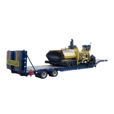
Etnyre BLACKHAWK RTN Series User manual

BLACKHAWK TRAILERS
Limited Series Paver Special
Classic Series Custom Series
MO-RTN-05
Serial Number Q27423 and Up
Supercedes manual number MO-RTN-02

WEBB Torque Specifications
HUBS
(for Pilot Mounted Disc-Wheels)
8 - 10 Stud Hubs
Applies to M22 X 1.5 studs/two piece flange nut.
Read and Understand the installation, service and safety instructions manual
before installing or servicing the hub. Failure to do so may result in personal
injury or death, and may result in a compromise of your vehicle’s safety
through loss or failure of a wheel or compromise the braking system.
Use a torque wrench to assure proper torque, failure to do so will compromise
your products service, life and safety. Under torque and over torque can cause
thread and/or nut damage, and may result in the loss of a wheel.
Recheck torque after the first 50 to 100 miles of service. Parts may seat natu-
rally, causing the torque to drop. Proper torque is essential for the service, life
and safety of this product.
DANGER
Recommended Torque Dry: 450 - 500 ft. lbs.
NOTE: All threads are right hand metric.
1. Tighten Flange Nuts to 50 ft. lb. using sequence
shown.
2. Check Disc-Wheel for proper positioning on pads
and proper seating against flange.
3. Tighten Flange Nuts to recommended torque using
sequence shown.
1
1
2
3
4
5
6
7
8
9
10
8
76
25
34
8 Stud Hubs
10 Stud Hubs


1
MO-RTN-05
RTN SERIES TRAILER
OPERATION MANUAL
WARRANTY
Etnyre Trailer Co. warrants to the original Purchaser, it’s new product to be free from defects in
material and workmanship for a period of six (6) months after date of delivery to original Purchaser.
The obligation of the Company is limited to repairing or replacing any defective part returned to the
Company and will not be responsible for consequential damages or any further loss by reason of such
defect.
The company excludes all implied warranties of merchantability and fitness for a particular
purpose. There are no warranties, express or implied, which extend beyond the description of
the goods contained in this contract.
This warranty does not obligate the Company to bear the cost of machine transportation in connec-
tion with the replacement or repair of defective parts, nor does it guarantee repair or replacement of
any parts on which unauthorized repairs or alterations have been made or for components not manu-
factured by the Company except to the extent of the warranty given by the original Manufacturer.
This warranty does not apply to:
(1) Normal start-up services, normal maintenance services or adjustments usually performed
by the selling dealer, factory service representative or customer personnel.
(2) Any product manufactured by Etnyre Trailer Co. purchased or subjected to rental use.
(3) Any product or part thereof which shows improper operation, improper maintenance,
abuse, neglect, damage or modification after shipment from factory.
(4)Any product or part thereof damaged or lost in shipment. Inspection for damage should be
made before acceptance or signing any delivery documents releasing responsibility of the
delivering carrier.
This warranty and foregoing obligations are in lieu of all other obligations and liabilities including
negligence and all warranties of merchantability or otherwise, express or implied in fact or by law.
ETNYRE TRAILER CO., Oregon, Illinois 61061-9778
1333 South Daysville Road Phone: 815/732-2116 Fax: 815-732-7400
Serial Number Q27423 and Up

2
GENERAL
Table Of Contents
Warranty............................................................................1
Safety Precautions, ...........................................................4
Hazard Seriousness Level ................................................4
Reporting Safety Defects ..................................................4
General .............................................................................4
Unit Nameplate or Certification Label ...............................5
Serial Number Data ..........................................................5
Trailer Capacity Data ........................................................5
Tire and Rim Data .............................................................5
System Specifications .......................................................5
Operating Instructions .......................................................5
Warning and Caution Information .....................................5
Figure 3. Unit Nameplate and Decals ...............................6
Model RTN35T..................................................................7
Model RTN55T..................................................................7
Table 1. Torque Specifications For Standard Hardware....8
General .............................................................................9
Trailer to Tractor Connecting Procedures .........................9
Gooseneck Removal.......................................................10
Gooseneck Attachment ................................................... 11
Multiple Ride Height Adjustment ..................................... 11
High Lift Gooseneck Operation ....................................... 11
Loading and Unloading Procedures................................13
General ...........................................................................13
Front Loading and Unloading Procedures ......................13
General Rear Loading and Unloading Procedures .........13
Ramps.............................................................................14
Shimming Instructions.....................................................16
Maintenance ...................................................................18
General ...........................................................................18
Table 2. Maintenance Schedule ......................................18
Table 3. Electrodes for Weld Repairs.............................20
Maintenance Procedures ................................................20
Frame Inspection ............................................................20
Weld Repairs...................................................................20
Wheel Bearings...............................................................20
Undercarriage .................................................................21
Service Guide-ridewell Suspensions ..............................21
Basic Operation ..............................................................21
Air Springs & Height Control Valve .................................21
Air Pressure & Brake Protection Valve............................22
Operational Inspection ....................................................22
Preventive Maintenance .................................................22
Welding Guidelines .........................................................23
Welding Methods, Materials & Personnel .......................23
Weld Joint Preparation....................................................23
Welding Procedure..........................................................23
Repair Welding................................................................24
Welding Precautions .......................................................24
Alignment Of Axle For Tandem Axle Trailer.....................25
Height Control Valve .......................................................25
Set Up .............................................................................25
Adjustment ......................................................................25
Valve Replacement .........................................................26
Tires And Disc Wheels ....................................................26
Tire Inflation ....................................................................26
Tire Overinflation .............................................................26
Tire Underinflation ...........................................................26
Matching Dual Tires ........................................................27
Removing Tire and Disc Wheel Assembly ......................27
Mounting and Demounting Tires on Disc Wheels ...........27
Mounting Tire and Hub Piloted Type Disc Wheels ..........27
Checking Tightness on Mounted Dual Disc Wheels .......28
Hubs................................................................................28
Hub Removal ..................................................................28
Inspection and Cleaning .................................................28
Hub Installation ...............................................................28
Air Systems and Brakes..................................................28
Air Systems and Brakes - General..................................28
Air System Tests .............................................................28
Air Reservoir ...................................................................29
Air Hoses and Tubing......................................................29
Brake Relay Emergency Valve........................................29
Air Brake Chambers........................................................29
Brake Air Supply System Description .............................29
Relay Emergency Valve ..................................................30
Brake Chambers .............................................................31
Brake Chamber Servicing ...............................................31
Brake Chamber Removal................................................31
Brake Chamber Disassembly .........................................31
Cleaning and Inspection of Parts ....................................32
Brake Chamber Assembly ..............................................32
Installation .......................................................................32
Air Brakes........................................................................32
General ...........................................................................32
Operating Checks ...........................................................32
Brake Assembly ..............................................................32
Slack Adjuster .................................................................33
Crewson Brunner Automatic Slack Adjuster ...................33
Recommended Preventive Maintenance ........................33
Every Three Months or 25,000 Miles ..............................33
Every Six Months or 50,000 Miles ..................................33
Testing Adjuster Function ................................................33
Slack Adjuster Replacement ...........................................34
Trouble Analysis for Air Brakes .......................................36
Electrical..........................................................................39
Lighting System ..............................................................39
Hydraulics .......................................................................39
General ...........................................................................39
Hydraulic Power Pack Filter ............................................39
Checking Hydraulic Reservoir Oil Level..........................39
Changing Hydraulic Oil ...................................................39
Hydraulic Power Pack Battery ........................................39
Adjusting Relief Pressure................................................40
Trouble Analysis for Hydraulic Systems ..........................40
3
GENERAL
Table Of Contents
Figure 1. Etnyre RTN ........................................................4
Figure 2. Unit Nameplate or Certification Label ................5
Figure 3. Unit Nameplate and Decals ...............................6
Figure 4. Standard Hardware............................................8
Figure 5. Inspection of Kingpin for wear ...........................9
Figure 6. Identification of Controls ..................................10
Figure 7. Compression Block Positions .......................... 11
Figure 8. Gooseneck to Platform Connections ............... 11
Figure 9. Ride Height Adjustment ...................................12
Figure 10. Extension Brackets ........................................13
Figure 11. Blocking Under Rear of Trailer .......................14
Figure 12. Maintenance Checkpoints .............................19
Figure 13. Check Oil Level of Oil Lubricated Bearings. ..21
Figure 14. Tightening Sequence .....................................21
Figure 15. Eccentric Bolt Inspection ..............................22
Figure 16. Root Weld Gap .............................................23
Figure 17. Multiple Pass Recommended Method ...........23
Figure 18. No Weld Zones ..............................................24
Figure 19. Alignment of Axle ...........................................24
Figure 20. Height Control ValveAsm ..............................25
Figure 21. Proper Tire Inflation .......................................26
Figure 22. Removal of Tires and Hub Piloted Wheels ....27
Figure 23. Checking Oil Level in Hub .............................28
Figure 24. Brake Air Supply System - 2Axle Shown ......29
Figure 25. Relay Emergency Valve.................................30
Figure 26. Brake Chamber..............................................31
Figure 27. Brake Components ........................................32
Figure 28. Slack Adjuster Lubrication Points ..................33
Figure 29. Measuring Maximum Stroke ..........................33
Figure 30. Gooseneck Socket Connection ....................39
Figure 31. Hydraulic Oil Check .......................................40
Figure 32. Directional Control Valve Pressure Relief ......40

4
GENERAL
Safety Precautions,
Hazard Seriousness Level
You will find safety information boxes throughout
this manual. These boxes contain information alerting
you to situations or actions to avoid.
Signal words (DANGER, WARNING and CAU-
TION) are used to identify levels of hazard serious-
ness. Their selection is based on the likely conse-
quence of human interaction with a hazard. Defini-
tions of hazard levels are as follows.
DANGER - Immediate hazards which
will result in severe personal injury or death.
WARNING - Hazards or unsafe prac-
tices which could result in severe personal
injury or death.
CAUTION - Hazards or unsafe prac-
tices which could result in minor personal
injury or product or property damage.
Reporting Safety Defects
If you believe that your vehicle has a defect which
could cause a crash or could cause injury or death, you
should immediately inform the National Highway Traf-
fic Safety Administration (NHTSA) in addition to no-
tifying E. D. ETNYRE & CO.
If NHTSA receives similar complaints, it may open
an investigation, and if it finds that a safety defect ex-
ists in a group of vehicles, it may order a recall and
remedy campaign. However, NHTSA cannot become
involved in individual problems between you, your
dealer, or
E. D. ETNYRE & CO.
To contact NHTSA, you may either call the Auto
SafetyHotline toll-free at1-800-424-9393 (or 366-0123
in Washington, D. C. area) or write to: NHTSA, U. S.
Department of Transportation, Washington, D. C.
20696. You can also obtain other information about
motor vehicle safety from the hotline.
GENERAL
This manual contains operation, maintenance and
service instructions for the Etnyre RTN Series trailers
(see figure 1). The operating instructions must be read
and understood before operating the unit. The operator
must be responsible for maintaining the unit in good
working condition.
To identify the maximum load capacity of your
trailer, examine the Etnyre model number. It contains a
condensed description of the unit.
This manual covers the standard features and op-
tions of the Etnyre Blackhawk series trailers. If your
trailer incorporates custom features, some of the infor-
mation contained in this manual may not apply. If you
haveany questions regarding this manualor your trailer,
contact your dealer or the E. D. Etnyre Service Depart-
ment at 1-800-995-2116.
A typical model number such as RTN35TD3-T1
would describe the following trailer:
RTN 35 TD3 T1
(A) (B) (C) (D)
A. The first group describes trailer type: RTN
model, removable gooseneck.
B. The second group indicates trailer capacity: 35
= thirty five U.S. tons.
C.Thethird groupdescribes trailerundercarriage
and platform: TD3 = triple axle undercarriage with
a drop deck (“TD” only indicates a tandem axle un-
dercarriage with a drop deck).
D. The fourth group describes additional informa-
tion: T1 = constructed using T1 steel.
Figure 1. Etnyre RTN
RR
OPERATINGINSTRUCTIONS
R

5
GENERAL
Unit Nameplate or Certification Label
The unit serial number plate or certification label is
located on the left hand gooseneck beam web. The
nameplate or certification label must remain perma-
nently affixed to the unit. (See figure 2).
Serial Number Data
The unit serial number on the certification label is
also stamped into the gooseneck beam web plate near
the nameplate and on the outside frame member at the
left hand forward corner of the frame. (See figure 2).
NOTE: The complete serial number must be iden-
tified when ordering parts or communicating ser-
vice information to Etnyre.
Trailer Capacity Data
Trailers manufactured in the United States list the
maximum"GrossVehicleWeight Rating" (GVWR) and
the maximum "Gross Axle Weight Rating" (GAWR)
on the certification label.
The Gross Vehicle Weight Rating is the sum of the
trailer weight and the trailer capacity. This is the maxi-
mum structural capacity of the trailer.
The GrossAxle Weight Rating is the maximum load
any axle can carry.
Thecertificationlabel shows "GVWR"and "GAWR"
at reduced speeds, at the bottom of the label. The
GVWR may be reached under certain circumstances
before the GAWR or vice versa.
WARNING
Do not exceed the GVWR or GAWR at the
specified speed. These weight limitations are
independent of road weight limitations imposed
by law.
Tire and Rim Data
The certification label lists the correct rim size, tire
size and tire inflation pressures for the trailer.
WARNING
Do not use undersize rims or tires. Do not underin-
flate or overinflate the tires.
System Specifications
Unit specifications are listed in the General Section
Figure 2. Unit Nameplate or Certification Label
Operating Instructions
Operating instructions are contained in the Opera-
tion Section.
WARNING
The operator must understand the operating
instructions completely before operating the
unit. Personal injury and/or damage to the unit
may occur if the operating instructions are not
followed.
Warning and Caution Information
Warning and caution information is given through-
out this manual. Particular care must be given to warn-
ing and caution information contained in the Operation
Section (Operating Instructions) and where noted with
proper service procedures in other sections.
NOTE: Warning and caution decals are affixed
toall unitsat thefactory.Thesedecals containwarn-
ingand cautioninformation which mustbe followed
by all persons operating or servicing an Etnyre
trailer. Any warning or caution decal which is lost,
ordifficultto read,mustbe replaced at once. Replace-
mentdecalsmay beobtainedfromanyEtnyretrailer
dealer.
R

6
GENERAL
Refer to Figure 3 for the location of the nameplate
and decals on the Etnyre trailer.
Care and maintenance information for your Etnyre
traileris given in the Maintenance section. Maintenance
schedules and recommended procedures must be fol-
lowed to maximize service life.
REF PART NO. QTY DESCRIPTION REF PART NO. QTY DESCRIPTION
1Q506064 1 Plate: Serial No. Plate, Trailer
2 Q514337 1 Decal: Operating Instruct., RTN
3Q512850 1 Decal: Gooseneck Supt, Pltf, Ht
4Q513124 1 Decal: Lift Arm Release Pos.
5 Q513123 1 Decal: Lift Arm Storage Pos.
6Q512962 1 Decal: Bird, RH
Q513296 1 Decal: Bird, LH
7Q512963 2 Decal: Word (Blackhawk)
8Q509853 1 Decal: Deck Height, 3 Pos
9Q513970 1 Decal: Gooseneck Air Lock Control
10 Q471243 2 Decal: Warning, Sideload
11 2790527 60 Tape-Conspicuity, 2 In., Red/White
12 Q451436 1 Decal: Return
13 Q451435 1 Decal: Pressure
14 Q401734 1 Decal: Attention T1 Steel
15 Q452390 1 Decal: Trademark, Patents
16 Q452415 1 Decal: Warning Proper Trailer Oper
17 Q419538 1 Splash Guard Group
18 Q513361 2 Decal: Etnyre Oval, Trailer
19 Q513963 1 Decal-Caution,Gooseneck Air Lock
Figure 3. Unit Nameplate and Decals
R
R R

7
GENERAL
Model RTN35T
Load capacity - 35 tons in any 16'-0" of deck
High lift gooseneck (35" travel)
Pin and stirrup design
Pin setting - 16"
Swing clearance - 84"
Fifth wheel height - 50" (adjustable +2" - no blocks)
Vertical gooseneck locking pin (air operated)
Concentrated load in 16'-0"
Main frame - 4 beam - 16" fully cambered
Deck height - 22" (adjustable - no blocks)
Ground clearance - 6" (adjustable - no blocks)
Deck width - 8'-6" (102")
Crossmember spacing - 20"
Decking - 1 1/2" Apitong (open center)
Front folding ramps - steel w/traction bars
Outriggers - 12" swinging/removable w/double hook-on
at front
Chain slots and flag holders in bolsters
Ridewell air suspension
±3" adjustable ride height
Tires - 255/70R 22.5 (H) 16 PR tubeless radials
Wheels - 8.25 x 22.5 steel disc (white)
Axles - 22,500# (5/8" wall thickness) with oil bearings
Axle spacing - 55"
Anti-lock brakes (2S/2M)
Brakes - 16 1/2" x 7" air
Spring brakes - one (1) axle (rear axle)
Storage baskets - 1 in rear of gooseneck, 1 section in deck
Model RTN55T
PRTN55ETD3-T1
Load capacity - 55 tons evenly distributed over
entire deck length
- 50 tons in any 16'-0" of deck with
close coupled 4th axle
PRTN55TD3-T1
Load Capacity - 55 tons in any 12’-0” of deck in 3+1
(14’-1” spread) axle configuration
High lift gooseneck (35" travel)
Pin and stirrup design
Pin setting - 16"
Swing clearance - 84"
Fifth wheel height - 50" (adjustable +2" - no blocks)
Vertical gooseneck locking pin (air operated)
Frame reinforced - For 4th axle.
Main frame - 4 beam - 16" fully cambered
Deck height - 22" (adjustable - no blocks)
Ground clearance - 6" (adjustable - no blocks)
Deck width - 8'-6" (102")
Crossmember spacing - 20"
Decking - 1 1/2" Apitong (open center)
Decking securement - deck screws
Front folding ramps - steel w/traction bars
Outriggers - 12" swinging/removable w/double hook-on at
front
Chain slots and flag holders in bolsters
Ridewell air suspension
+3" Adjustable ride height
Tires - (12)255/70R 22.5 (H) 16 PR tubeless radials
Wheels - 8.25 x 22.5 steel disc (white)
Axles - 22,500# (5/8" wall thickness) with oil bearings
Axle spacing - 55"
Anti-lock brakes - none (trailer exceeds 120,000# GVWR)
Brakes - 16 1/2" x 7" full air
Spring Brakes - one (1) axle (center axle)
Storage baskets - 1 in rear of gooseneck & 1 section in
deck
NOTE:All specifications are subject to change with-
out notice. Weights and dimensions are shown fully
loaded and are approximate. Platform heights will in-
crease if loaded at less than full capacity.

8
GENERAL
Table 1. Torque Specifications For Standard Hardware
NOTE: This table lists torque values for standard hardware and is intended as a guide for average applications
involving typical stresses and machined surfaces. Values are based on the physical limitations of clean, plated and
lubricated hardware. In all cases, when an individual torque value is specified, it should take priority over values given
in this table. Replace original equipment with hardware of equal grade.
Figure 4. Standard Hardware
GRADE 8GRADE 5 PLACEBOLT SOCKET HEAD
CAPSCREW 12 POINT
CAPSCREW
SAE Grade 5 Capscrews SAE Grade 8 Capscrews
Nominal Thread Torque Torque Torque Torque
Size Series (ft. lbs.) (Nm) (ft. lbs.) (Nm)
DRY LUBED DRY LUBED DRY LUBED DRY LUBED
1/4 20 UNC 8 6 11 9 12 9 16 12
28 UNF 10 7 13 10 14 10 19 14
5/16 18 UNC 17 13 24 18 25 18 33 25
24 UNF 19 14 26 20 27 20 37 28
3/8 16 UNC 31 23 42 31 44 33 59 44
24 UNF 35 26 47 36 49 37 67 50
7/16 14 UNC 49 37 67 50 70 52 95 71
20 UNF 55 41 75 56 78 58 105 79
1/2 13 UNC 75 57 100 77 105 80 145 110
20 UNF 85 64 115 86 120 90 165 120
9/16 12 UNC 110 82 145 110 155 115 210 155
18 UNF 120 91 165 125 170 130 230 175
5/8 11 UNC 150 115 205 155 210 160 285 215
18 UNF 170 130 230 175 240 180 325 245
3/4 10 UNC 265 200 360 270 375 280 510 380
16 UNF 395 225 405 300 420 315 570 425
7/8 9 UNC 430 320 580 435 605 455 820 615
14 UNF 475 355 640 480 670 500 905 680
1 8 UNC 645 485 875 655 910 680 1230 925
14 UNF 720 540 980 735 1020 765 1380 1040
1 - 1/8 7 UNC 795 595 1080 805 1290 965 1750 1310
12 UNF 890 670 1210 905 1440 1080 1960 1470
1 - 1/4 7 UNC 1120 840 1520 1140 1820 1360 2460 1850
12 UNF 1240 930 1680 1260 2010 1500 2730 2050
1 - 3/8 6 UNC 1470 1100 1990 1490 2380 1780 3230 2420
12 UNF 1670 1250 2270 1700 2710 2040 3680 2760
1 - 1/2 6 UNC 1950 1460 2640 1980 3160 2370 4290 3210
12 UNF 2190 1650 2970 2230 3560 2670 4820 3620

9
OPERATION
General
This section contains information required for the
operation of Etnyre model trailers.
WARNING
Read these instructions thoroughly and
observe them when operating Etnyre trailers.
Operate by Authorized, Trained personnel
Only!
The trailer must be maintained in good operating
condition. Minor damage can quickly result in a major
failure if not repaired.
WARNING
Do not operate a trailer needing repair.
Do not undersize the prime mover. The prime
mover (tractor) must be compatible with the
trailer and have adequate capacity.
Do not permit the bottom of a trailer with low
ground clearance to hit or slide on or over
curbs, railroad crossings or other obstructions
that can cause damage to the trailer or stall the
vehicle.
Do not exceed either the GVWR or GAWR
shown on the certification label. These ratings
are listed for trailers at various speeds and
reflect the maximum GVWR and GAWR at
those speeds.
Keep personnel clear when loading and
unloading trailers.
Trailer to Tractor
Connecting
Procedures
1. Inspect the fifth wheel area and the trailer frame
for wear, structural cracks, damaged or broken deck-
ing.
2. Check the kingpin for wear or damage. Replace it
if the diameter measures less than 1 7/8" at any point
(see figure 5).
3. Check the bolts for tightness. Tighten if required.
Refer to Table 1 for correct torque values.
4. Connect the trailer to the fifth wheel..
5. Connect the glad hands and build up reservoir air
pressure. Make sure that air line connections between
trailer and truck are made.
6. Connect the plug into the electrical socket. Make
sure that electrical connection between trailer and truck
is made.
7. Check the lights, turn signals and reflectors for
operation.
Figure 5. Inspection of Kingpin for wear
WARNING
Check to insure that the kingpin is locked into
the tractor fifth wheel.
8. Before operating the trailer, test the air brake sys-
tem using the following procedure:
a. Check the air system pressure. The system must
hold 100 PSI (7 Bar) minimum.
b. Apply the brakes. Inspect the brake action on all
the wheels for proper application.
c. Release the brakes. The brakes must release
promptly. The air pressure must discharge quickly from
the relay emergency valve.
d. Disconnect the emergency line from the trailer.
The trailer brakes must automatically apply.
e. Connect the emergency line to the trailer. The
trailer brakes must release.
9. Check the tires for proper inflation pressure. In-
spect the tires for cuts or other damage.
10. Power pack operated units, start engine and
adjust the throttle. Truck operated units, hook up hy-
draulic lines and engage the pump.

10
OPERATION
WARNING
Make sure that the gooseneck to platform
safety pin is fully engaged. If the pin is
disengaged, the gooseneck could drop
uncontrollably to the ground.
7. Disconnect the fifth wheel lock pin.
8. Pull tractor away from the trailer.
WARNING
Keep hands and feet clear of the point where
the frame contacts the ground.
Gooseneck Removal
(See figures 6 and 7)
1. Set tractor brakes.
2. Power pack units, start the engine and adjust the
throttle. Truck operated units, hook up hydraulic lines
and engage the pump.
3. Move the platform height control knob to the
“Raise” position until the platform lifts enough to free
the compression blocks.
4. Rotate the compression block handle to the “Re-
lease” position. See figure 7.
5. Move the platform height control knob to the
“Lower” position until the platform is on the ground
and the gooseneck teardrops are approximately 1/4”
below platform the pins.
6. Disconnect the electrical and air connection be-
tween the gooseneck and the platform.
7. Pull the safety pin handle out and rotate to hold it
out. Release the gooseneck lock pin (Pull switch out),
if pin will not release, back trailer up slightly). See fig-
ure 6.
8.Move the support arm control knob to the “Lower”
position until the support arm contacts the truck frame
and supports the gooseneck.
WARNING
Keep hands and feet clear of the point where
the frame contacts the ground.
9. Power pack units - shut off power pack engine.
Truck operated units - disengage truck pump.
Figure 6. Identification of Controls
11. Move the platform height control to the "Raise"
position until the compression blocks fall into the
"Transport" position.
12. Move the platform height control to the "Lower"
position until the compression blocks are completely
seated.
13. Insure that gooseneck support arm is fully re-
tracted.
14. Power pack operated units, shut off engine.
Truck operated units, disengage pump.
Trailer to Tractor
Disconnection
Procedure
1. Disconnect the electrical and air connection be-
tween the gooseneck and the truck.
WARNING
Block the trailer wheels
2. Power pack operated units, start the engine and
adjust the throttle. Truck operated units, hook up hy-
draulic lines and engage pump.
3. Move the platform height control to the
“Raise” position until the compression blocks disen-
gage the gooseneck link (refer to figure 7).
4. Rotate the compression blocks to the “Re-
lease” position (refer to figure 7).
5. Move the platform height control to the
“Lower” position until the platform is on the ground
and the load is removed from the tractor fifth wheel.
6. Powerpackoperated units, shut off power pack
engine. Truck operated units, disengage truck pump
and disconnect hydraulic lines from the truck.
Platform
Height
Control
Support Arm
Control
Operating
Instructions
Decal
Electric and Air
Connections -
Gooseneck to Platform
Gooseneck
Lockpin Switch
Lockpin
Safety Handle
Compression
Block Handle

11
OPERATION
10. Pull tractor and gooseneck away from the plat-
form to permit loading.
Gooseneck Attachment
(See figures 6 and 7)
1. Pull the safety pin handle out and rotate to hold it
out. Release the gooseneck lock pin (Pull switch out).
2. Back gooseneck into the platform until gooseneck
tear drops contact platform.
3.Powerpack units- startengine and adjust throttle.
Truck operated units - engage pump.
4. Move the support arm control knob to the “Raise”
position until the support arm is fully retracted.
5. Move the platform height control knob to the
“Raise”position until thecompression blocks canswing
into the desired “transport position”.
6. Rotate compression block handle to the selected
transport position.
7. Move the platform height control knob to the
“Lower”position until the compression blocks are com-
pletely seated.
8. Engage the gooseneck lock pin (Push switch in).
Rotate the safety pin handle, and push it in to engage it.
8. Power pack units - shut off engine. Truck oper-
ated units - disengage pump.
9.Connect the electrical and air connections between
the gooseneck and the platform.
Multiple Ride Height Adjustment
The RTN trailer gooseneck can be adjusted to
provide a standard ride height with a range of tractor
fifth wheel heights or multiple ride heights with any
given fifth wheel height. This adjustment is accom-
plished by positioning the compression blocks to mesh
with the gooseneck link through a range of positions.
An adjustable stop cam is provided to stop the com-
pression blocks in a preselected position. See figure 9.
NOTE:Thetop tooth of the compression block must
always be above the top tooth of the gooseneck link
when the block and link are engaged in the travel posi-
tion. Likewise, the bottom tooth of the compression
block must always be below the bottom tooth of the
gooseneck link (see figure 9).
WARNING
All teeth on the gooseneck link must be fully
engaged with the compression block when in
the Travel position.
Figure 7. Compression Block Positions
Figure 8. Gooseneck to Platform Connections
High Lift Gooseneck Operation
The Etnyre RTN trailer features a High Lift goose-
neck. This gooseneck provides 32” of vertical travel at
the front of the trailer platform, allowing the trailer to
clear obstacles or to avoid “high centering”.
Raise the trailer only high enough to clear the
obstacle. Travel speeds while in the High Lift position
must be limited to 10 mph maximum and the trailer
Teeth Engaged
Compression Blocks
Compression
Block Handle
Gooseneck
Link
Compression Blocks in
"Travel" Position
Teeth Disengaged
Compression
Block Handle
Gooseneck
Link
Compression Blocks
Compression Blocks
Rotated to
"Release" Position
Gooseneck Lockpin Switch
Compression
Block Handle
Gooseneck
Link
Compression Blocks
Air Operated Lockpin

12
OPERATION
must be towed only in a straight line due to tractor
fifth wheel oscillation limitations. Attempting to turn
while the trailer is in the High Lift position could dam-
age the tractor and/or the trailer.
Figure 9. Ride Height Adjustment
WARNING
Do not raise loaded trailer so high as to lift the
front axle off the ground. Damage to the trailer
frame and/or suspension could occur.
WARNING
Do not make turns with the trailer in the high lift
position. Damage to the trailer and/or tractor
could occur.
Compression
Block Handle
Compression Block Position
for
Minimum Fifth Wheel Height
or Maximum Ride Height
Compression
Block Handle
Compression Block Position
for
Maximum Fifth Wheel Height
or Minimum Ride Height

13
OPERATION
Loading and Unloading Procedures
General
The model RTN trailers are front loaded by detach-
ing the gooseneck. The detached gooseneck is then
moved away with the tractor and the trailer is front
loaded.
WARNING
Read these instructions thoroughly and
observe them when operating hydraulic
removable gooseneck trailers.
Also read and observe the general operating
procedures for trailers at the beginning of this
section.
Front Loading and Unloading Procedures
These procedures mustbe followed when front load-
ing or unloading hydraulic removable gooseneck trail-
ers.
WARNING
Load and unload on solid, level terrain.
1. Set the brakes on the trailer.
WARNING
Block the trailer wheels.
2. Use extension brackets (optional equipment) to
increase the platform width to support wide loads.
WARNING
Use care when loading and unloading. Move
the machine on or off the trailer slowly!
Extension bracket will not support the full load
weight.
3. Center the load. Do Not load to one side. Position
the load for proper weight distribution.
4. Fasten the load to the trailer.
WARNING
The load must be securely and adequately
fastened to the trailer.
WARNING
Keep hands and feet clear of the point where
the frame contacts the ground.
WARNING
Extension Brackets
Maximum width not to exceed trailer width
Centerline of Centerline of
Tracks or Tires Tracks or Tires
Top of extension bracket boards must be flush
with main deck boards.
Centerline of tracks or tires must be loaded on
the main deck, not on the extension brackets.
Failure to load extension brackets properly can
result in equipment damage and personal
injury.
Figure 10. Extension Brackets
General Rear Loading and Unloading
Procedures
These procedures Must be followed when rear load-
ing or unloading trailers (the Rear Loading Feature is
optional equipment).
Centerline of
Tires or Tracks Centerline of
Tires or Tracks
Maximum width not to exceed trailer width
Extension Brackets

14
OPERATION
WARNING
Load and unload on solid, level terrain.
All rear loading trailers must be connected to the
prime mover (tractor) during all rear loading and un-
loading procedures.
1. Set the brakes on the prime mover and trailer.
WARNING
Block the trailer wheels.
2. When loading or unloading the trailer from the
rear, block under the rear of the trailer frame and under
the load ramps (see figure 11).
NOTE: Place blocks under the load ramps to sup-
port the ramps during loading or unloading. These trail-
ers can also be loaded and unloaded from a dock or
embankment.
3. Use extension brackets (optional equipment) to
increase the platform width to support wide loads.
WARNING
Use care when loading and unloading. Move
the machine on or off the trailer slowly!
Extension bracket will not support the full load
weight.
4. Center the load. Do Not load to one side. Position
the load for proper weight distribution.
5. Fasten the load to the trailer.
General Road Check Procedures
During road stops, check the trailer and the load us-
ing the following procedures:
1. Check the fastening equipment.
WARNING
The load must be securely and adequately
fastened to the trailer.
2. Inspect the trailer frame structure.
3. Check all the trailer brake drums for heating.
NOTE:A cool brake drum can indicate an inopera-
tive brake.
WARNING
The load must be securely and adequately
fastened to the trailer.
WARNING
Proceed cautiously since a malfunctions or
misadjusted brake can cause the drum to
become extremely hot. Do Not operate the
trailer until the cause of overheating is
corrected.
Figure 11. Blocking Under Rear of Trailer and Under Load Ramps.
Sloping
After Deck
Ramp
Ramp
Blocks
Blocks

15
OPERATION
4. Check to be sure all the wheel nuts are tight.
Tighten as required (see Figure 14),
5. Check the tire inflation. Inspect the tires for cuts
or other damage.
WARNING
Do Not bleed air from the tires when they are
hot.
6. Inspect the lights, turn signals and reflectors for
operation.
WARNING
Do Not operate a trailer needing repair. Correct
any problems found during the road check
immediately.

16
OPERATION
Shimming Instructions
Shim
Point
A
Deck
Shim Deck to
Rear Section
so Bottom Beam
Flanges are Level.
(May require blocking
under deck to open
Shim Point A.)
Deck Shim
(attached)
Rear Section
Shimming requires exhausting of the air ride system to open
shim points!
Trailer may be adjusted using manual raising and lowering valve
or +3/-3 height control.
Air pressure gauges may be located on suspension air bag for
developing air pressure for axle load charts.
Shimming objective is to have all rear section bottom beam flanges level (top
of axle to bottom flange of rear beam should be 6 1/2" at standard ride height).
A chart should be kept of all the loads that require shimming and must be
developed through trial and error.
This manual suits for next models
4
Table of contents
Other Etnyre Utility Vehicle manuals

Etnyre
Etnyre Centennial A-130-12R User manual

Etnyre
Etnyre Black-Topper BT-1 Distributors 2008 Technical manual

Etnyre
Etnyre Street Flusher Instruction Manual

Etnyre
Etnyre Black-Topper SHOOTER Series User manual

Etnyre
Etnyre PAVER SPECIAL RPS Series User manual

Etnyre
Etnyre Black-Topper CENTENNIAL S-2000 Series Service manual

Etnyre
Etnyre Black-Topper Shooter II User guide

Etnyre
Etnyre Black-Topper User manual

Etnyre
Etnyre Black-Topper CENTENNIAL User guide

Etnyre
Etnyre M-752-02R1 User manual