5
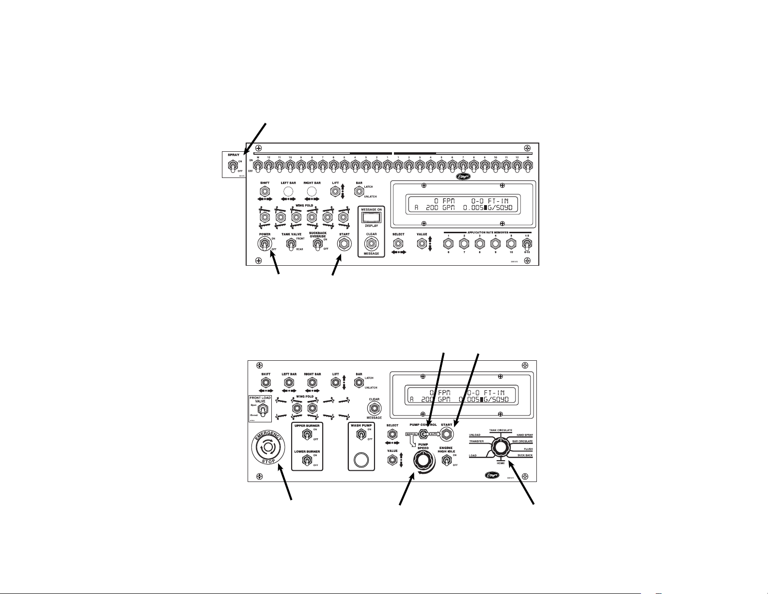
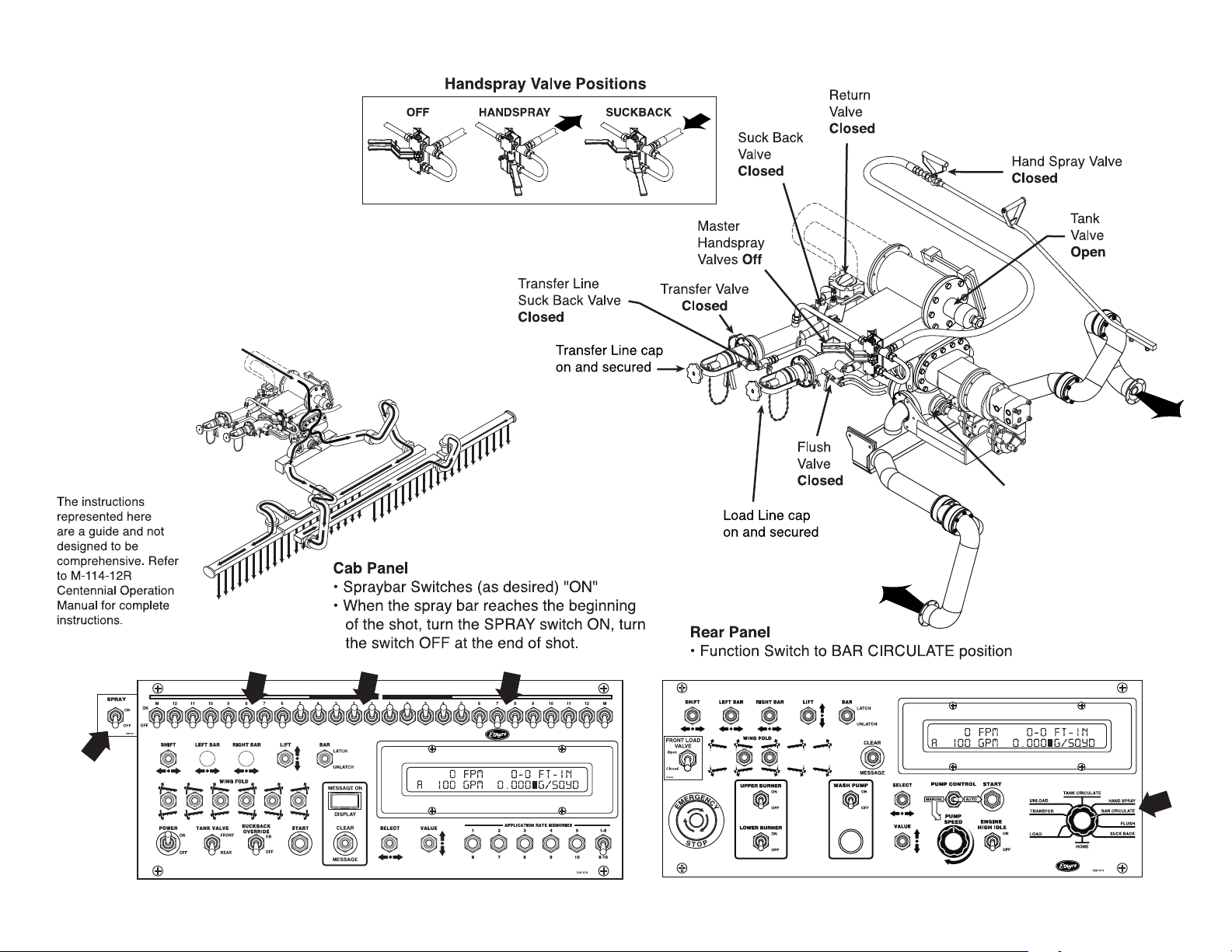
1. SPRAY Switch
Turning this switch to ON when the
Function knob (rear panel) is turned
to BAR CIRCULATE or BAR SUCK
BACK, opens all activated spray
valves.
2. START Button
Starts the asphalt pump turning at the
target pump rate or starts calibration
operations in the setup screens.
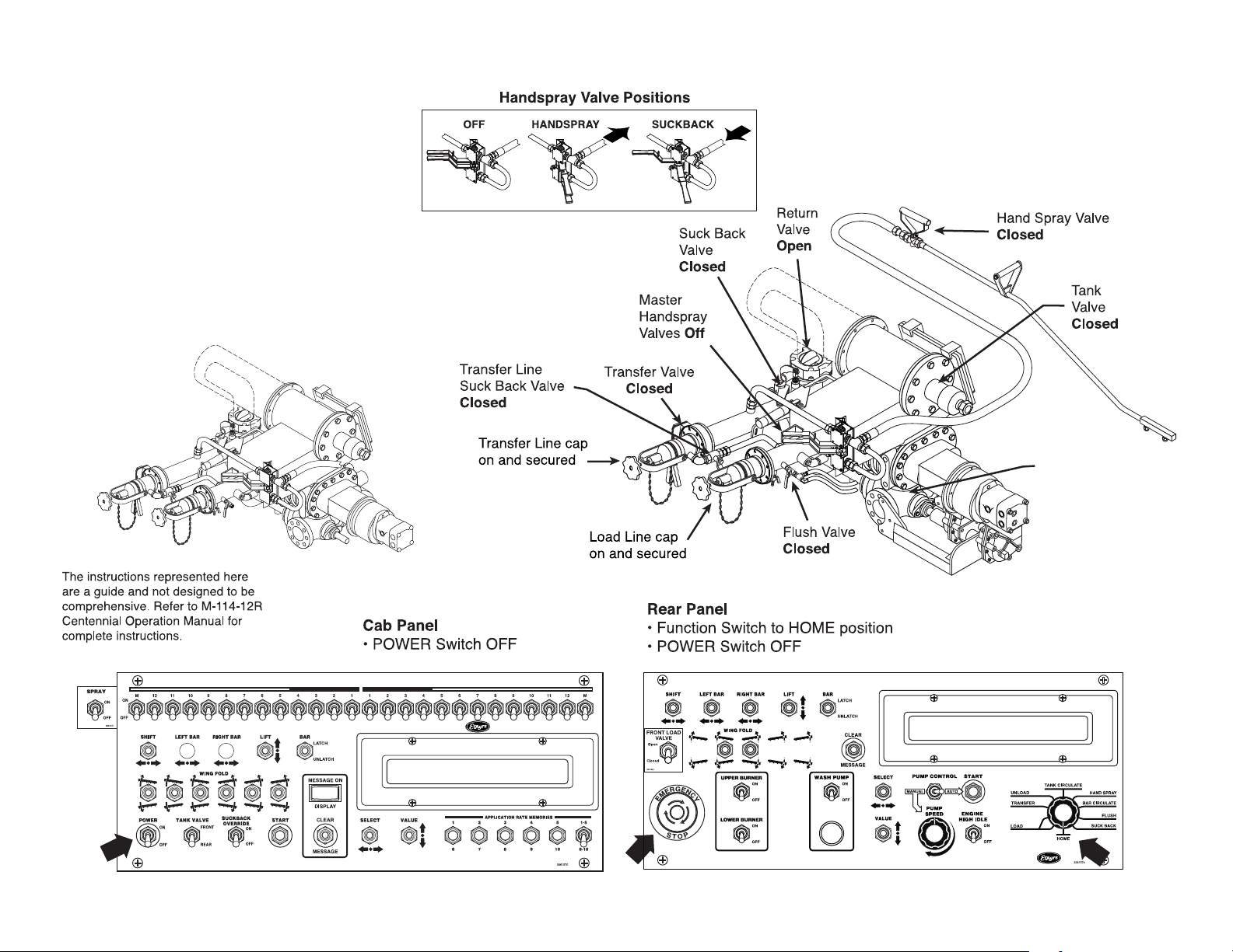
3. POWER Switch
Both POWER switches, front and rear,
must be ON for the system to be ON.
The entire system can be shut down
by turning either POWER switch to
OFF. Before turning either POWER
switch to ON be sure you know what
will automatically activate.
4. PUMP SPEED Control Knob
When MANUAL PUMP CONTROL
is selected, turning this knob to
the right (clockwise) increases the
asphalt pump speed. It is possible
to over-speed the asphalt pump in
MANUAL control since the asphalt
pump speed is also dependent on the
engine speed.
Always turn the knob back to the left
(counter-clockwise) before selecting
AUTO PUMP CONTROL or turning
ON either POWER switches (front
or rear).
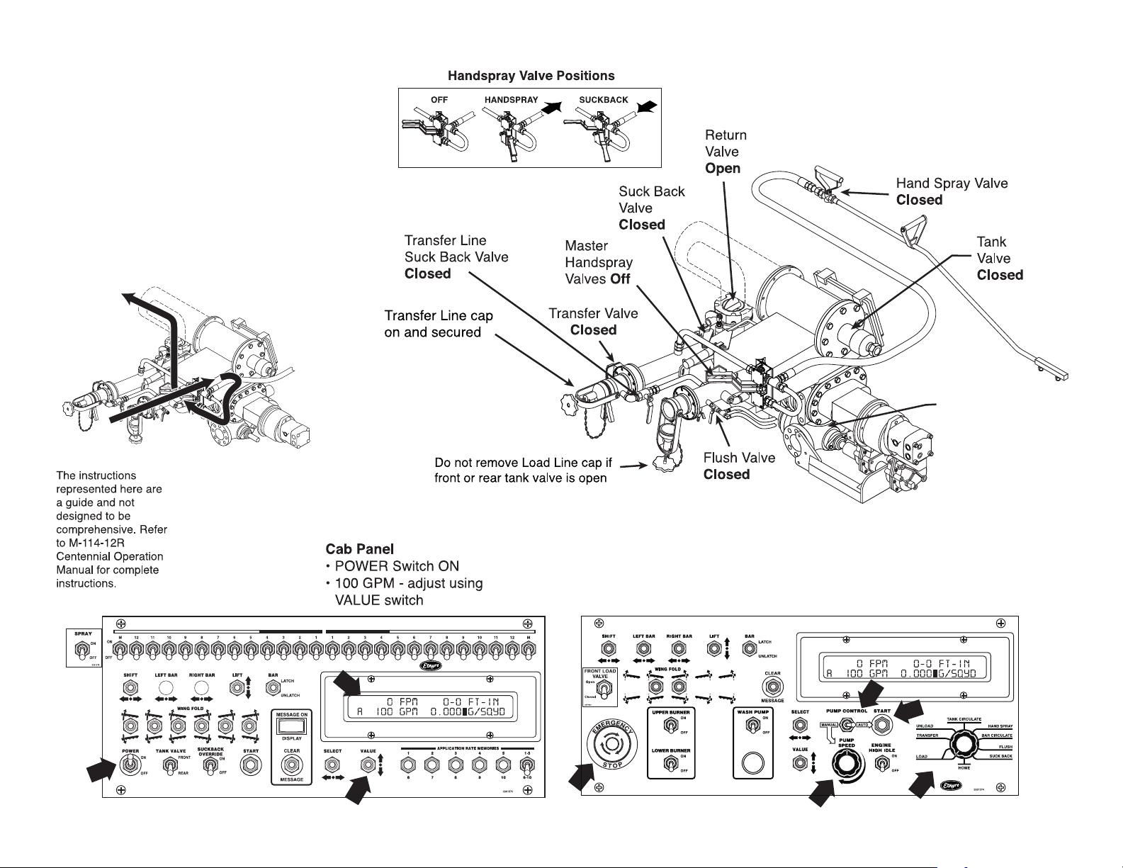
5. Function knob
When the desired operation is se-
lected through this knob, the asphalt
pump stops turning if the PUMP CON-
TROL is in AUTO, and all automatic
valves (tank valve, 4-way valve, bar
suck back valves, and balance valves)
are set for the desired operation. The
asphalt pump rate is set to the stored
preset for the desired operation.
The factory pump rate presets are:
• LOAD/TRANSFER - 100 GPM
• TANK CIRCULATE - 150 GPM
• BAR SUCK BACK - 200 GPM
• BAR FLUSH - 100 GPM
• UNLOAD - 100 GPM
• HAND SPRAY - 50 GPM
When BAR CIRCULATE is selected,
the asphalt pump rate is calculated
based on the displayed spray width,
application rate, and the setting of the
%CIRC factor.
6. PUMP CONTROL Switch
With the switch turned to AUTO, the
asphalt pump speed is controlled at
the desired rate through the com-
puter.
With the switch turned to MANUAL,
the asphalt pump speed is controlled
with the PUMP SPEED control knob at
the desired rate for a specic engine
speed.
Control Panels
Cab Control Panel
Rear Control Panel