3
Do not use this machine for any operation which
is not described in the Operation manual.
If you have any questions about the operation of
this machine, contact the Etnyre Service Depart-
ment at 1-888-586-1899.
Operations that are not approved could cause
serious injury or death.
Important
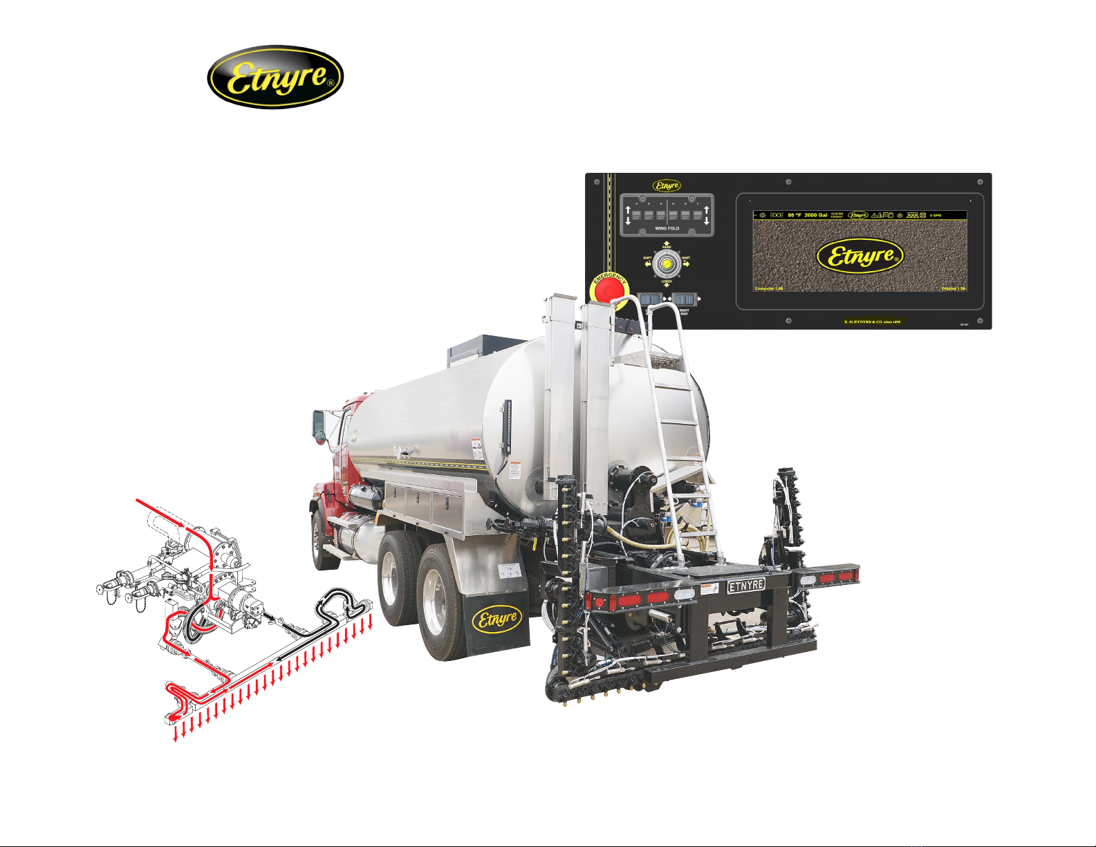
The instructions represented here are a guide and not designed
to be comprehensive. Refer to M-103-22 Asphalt Distributor
Operation, Maintenance and Safety manual for complete
instructions.
This pamphlet is provided as a tool to aid personnel in the
operation of the Etnyre Blacktopper Distributor, as with any type
of construction equipment, there are certain hazards associated
with improper or careless operation. The ability to read and
understand the instructions should be a required qualication
to become an operator. There are also functions that require
a certain amount of physical strength to accomplish. Persons
lacking the required strength may not only place themselves in
jeopardy, but also others in the vicinity. Read and understand
the Safety precautions found in M-103-22 Asphalt Distributor
Operation, Maintenance and Safety manual before operating
this machine.
If you have any questions regarding this pamphlet or the
operation of your unit, contact your Etnyre dealer or the
E. D. Etnyre Service Department at 1-888-586-1899.
WARNING
Contents
Etnyre Spray Bar Nozzles ...........................................2
Bar Suck Back Override ..............................................4
Control Panels.............................................................5
Load through Manhole.................................................6
Load through Load Line...............................................7
Circulate In Tank..........................................................8
Circulate In Bar............................................................9
Spray .........................................................................10
Suckback Spraybar ...................................................11
Handspray .................................................................12
Suckback Handspray ................................................13
Flushing Bar - AUTO .................................................14
Flushing Bar - MANUAL ............................................15
Unload (with External Pump).....................................16
Unload (with Distributor Pump)..................................17
Transfer .....................................................................18