Etnyre M-752-02R1 User manual

M-752-02R1
Starting with Serial Number V1001
Updated May 24, 2016
R
Falcon Series
Live Bottom Trailer
E. D. ETNYRE & CO., 1333 S. Daysville Road, Oregon, Illinois 61061-9778
Phone: 815-732-2116 or 800-995-2116 • Fax: 800-521-1107 • www.etnyre.com

1
GENERAL INFO & ID
M-752-02R1
Starting with S/N V1001
Updated May 24, 2016
LIVE BOTTOM
OPERATION MANUAL
HOW TO ORDER PARTS
To assure prompt delivery when ordering parts, please furnish the following information: 1)
Complete name and address of consignee. 2) Method of shipment preferred. 3) Is shipment
to be prepaid or collect? 4) Serial numbers of units to which parts apply. 5) Complete part
numbers and descriptions. 6) Any special instructions.
Specify unit serial number when ordering parts!
UNIT WARRANTY
E. D. Etnyre & Co. warrants to the original Purchaser, its new product to be free from defects in
material and workmanship for a period of twelve (12) months after date of delivery to original
Purchaser. The obligation of the Company is limited to repairing or replacing any defective part
returned to the Company and will not be responsible for consequential damages or any further loss
by reason of such defect.
This warranty does not obligate the Company to bear the cost of machine transportation in connection
with the replacement or repair of defective parts, nor does it guarantee repair or replacement of any
parts on which unauthorized repairs or alterations have been made or for components not manufac-
tured by the Company except to the extent of the warranty given by the original Manufacturer.
This warranty does not apply to:
(1) Normal start-up services, normal maintenance services or adjustments usually performed
by the selling dealer, factory service representative or customer personnel.
(2) Any product manufactured by E. D. Etnyre & Co. purchased or subjected to rental use.
(3) Any product or part thereof which shows improper operation, improper maintenance, abuse,
neglect,damageormodicationaftershipmentfromfactory.
(4) Any product or part thereof damaged or lost in shipment. Inspection for damage should be
made before acceptance or signing any delivery documents releasing responsibility of the
delivering carrier.
This warranty and foregoing obligations are in lieu of all other obligations and liabilities including
negligence and all warranties of merchantability or otherwise, express or implied in fact or by law.
Thecompanyexcludesallimpliedwarrantiesofmerchantabilityandtnessforaparticularpurpose.
There are no warranties, express or implied, which extend beyond the description of the goods
contained in this contract.
E. D. ETNYRE & CO., Oregon, Illinois 61061-9778
1333 South Daysville Road Phone: 800-995-2116 Fax: 800-521-1107
www.etnyre.com
R

2
GENERAL INFO & ID
Table Of Contents
GENERAL INFO & ID
HOW TO ORDER PARTS ................................................. 1
UNIT WARRANTY............................................................. 1
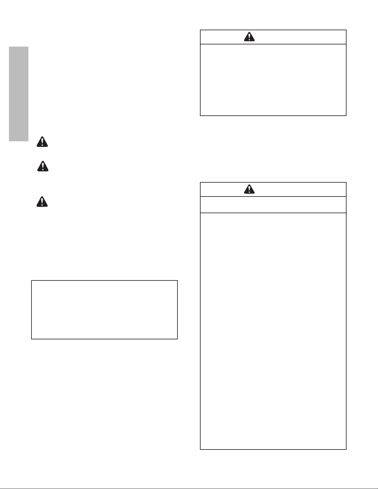
Safety Precautions, Hazard Seriousness Level ................ 4
Introduction................................................................... 5
Reporting Safety Defects............................................ 5
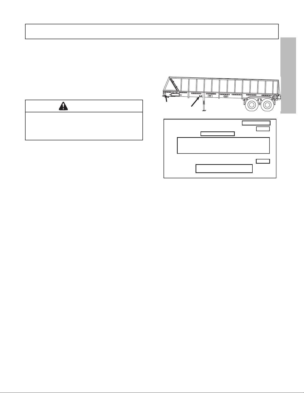
Unit Nameplate or Certication Label......................... 5
Serial Number Data.................................................... 6
Trailer Capacity Data.................................................. 6
Tire and Rim Data....................................................... 6
Care and Maintenance ............................................... 6
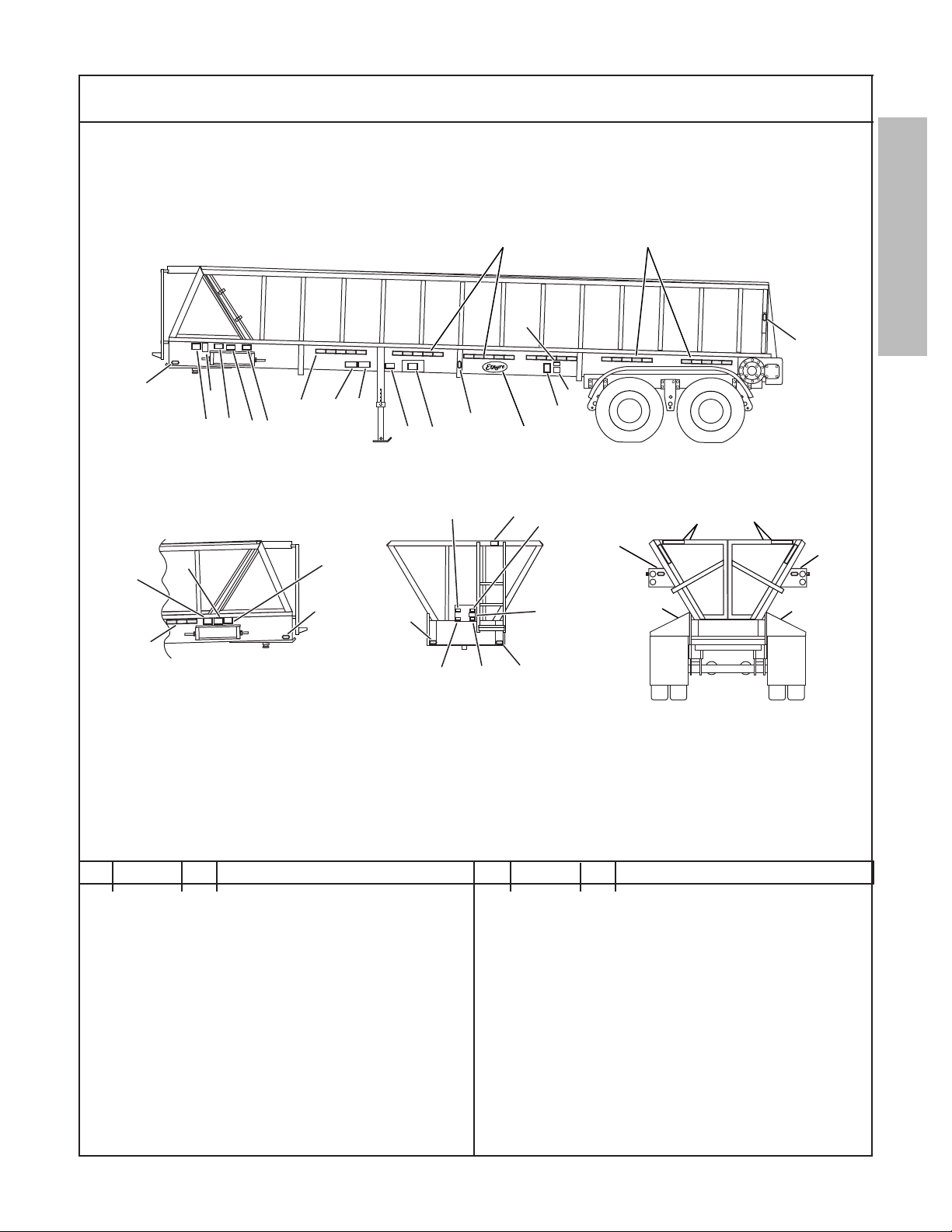
Decals And Warnings................................................... 7
Webb Hubs........................................................................ 9
OPERATION
Operation Instructions............................................... 10
General Description of Operation............................ 10
Pump Performance Recommendations................... 10
General.................................................................... 10
Trailer to Tractor Connecting Procedures.................10
Unloading Without Flow Control Valve .................... 11
Trailer Loading General Information........................ 11
Operating the Manual Tarp (optional)...................... 11
Lift Axle Operation ................................................... 12
Hendrickson Air Lift Control Decal L402.................. 13
Hendrickson Air Lift Control Kit AK-163 Schematic.... 15
MAINTENANCE
Maintenance Instructions .......................................... 16
General.................................................................... 16
Maintenance Schedule ............................................ 16
Maintenance Procedures......................................... 18
Frame Inspection..................................................... 18
Weld Repairs ........................................................... 18
Wheel Bearings ....................................................... 18
Undercarriage.......................................................... 18
Suspension Alignment & Fastener Torque .............. 19
Torque Specications .............................................. 19
Alignment Adjustment.............................................. 19
Tires, Rims and Disc Wheels................................... 20
Tire Ination .......................................................... 20
Tire Overination .................................................. 20
Tire Underination ................................................ 20
Matching Dual Tires.............................................. 20
Removing Tire and Rim Assemblies..................... 20
Removing Tire and Disc Wheel Assemblies ......... 20
Mounting and Demounting Tires
on Rims or Disc Wheels ...................................... 22
Mounting Tire and Rim Assemblies ...................... 22
Mounting Tire and Hub Piloted Type
Disc Wheels......................................................... 22
Mounting Tire and Ball Seat Type
Disc Wheel Assemblies ....................................... 22
Checking Tightness on Mounted Disc Wheels .... 23
Wheels and Hubs................................................ 23
General.............................................................. 23
Cast Wheel or Hub Removal............................. 23
Inspection and Cleaning.................................... 23
Cast Wheel or Hub Installation.......................... 23
Rim Mounting Instructions................................. 23
Careless Mounting is the Major Cause of
Tire and Rim Problems ...................................... 23
Mounting Procedure .......................................... 23
Check Wheel Alignment .................................... 24
Special Note on Aluminum Wheels ................... 24
Examine Wheels at Frequent Intervals.............. 24
Air Systems and Brakes ............................................ 25
Air Systems and Brakes - General .......................... 25
Air System Tests ...................................................... 25
Air Reservoir ............................................................ 25
Air Hoses and Tubing .............................................. 25
Brake Relay Emergency Valve ................................ 25
Air Brake Chambers ................................................ 25
Brake Air Supply System Description...................... 25
Relay Emergency Valve .......................................... 26
Brake Chambers ................................................. 26
Brake Chamber Servicing.................................. 26
Brake Chamber Removal .................................. 27
Brake Chamber Disassembly............................ 27
Brake Chamber Assembly................................. 27
Trailer ABS......................................................... 27
Installation ......................................................... 27
Air Brakes............................................................... 28
Air Brakes - General ............................................. 28
Operating Checks................................................. 28
Brake Assembly.................................................... 28
Slack Adjuster................................................... 29
Crewson Brunner Automatic Slack Adjuster.... 29
Recommended Preventive Maintenance......... 29
Every Three Months or 25,000 Miles............... 29
Every Six Months or 50,000 Miles................... 29
Testing Adjuster Function ................................ 29
Slack Adjuster Replacement............................ 31
Conveyor System Maintenance....................................... 32
TROUBLE ANALYSIS
Trouble Analysis for Hydraulic Systems .......................... 33
Trouble Analysis for Air Brakes........................................ 34
CONVEYOR / TARP MAINTENANCE
Conveyor System Maintenance....................................... 37
Cover Tarp Maintenance ................................................. 40
COMMENT / SUGGESTION FORM.................................41

3
GENERAL INFO & ID
List Of Figures
Figure 1. Certication Label............................................... 5
Figure 2. Decals & Markings ............................................. 7
Table 1 Torque Specications for Standard Hardware ... 8
Figure 3. Standard Hardware ............................................ 8
Figure 4. Measuring Kingpin............................................ 10
Table 2. Maintenance Schedule ................................... 16
Figure 5. Crank Handle
Figure 6. Maintenance Checkpoints................................ 17
Table 3. Electrodes for Weld Repairs. ......................... 18
Figure 7. Check Oil Level of Oil Lubricated Bearings...... 19
Figure 8. Lug Tightening Sequence................................. 19
Figure 9. Checking Alignment.......................................... 19
Figure 10. Proper Tire Ination........................................ 20
Figure 13. Removal of Tires and Hub Piloted Wheels..... 21
Figure 14. Rim Mounting Surfaces...................................23
Figure 15. Assembling Rims and Spacers....................... 24
Figure 16. Rim Clamp Tightening Sequence................... 24
Figure 17. Checking Oil Level in Hub.............................. 24
Figure 18. Tightening Sequence of Std Disc Wheels ...... 26
Figure 19. ABS Electrical Connections............................ 28
Figure 20. ABS Brake Air Supply System........................ 28
Figure 21. Slack Adjuster Lubrication Points................... 29
Figure 22. Relay Emergency Valve ................................. 30
Figure 23. Brake Chamber .............................................. 30
Figure 24. Measuring Maximum Stroke........................... 31
Figure 25. Gearbox Drain and Check Plugs.................... 37
Figure 26l. Left Side Conveyor Take-up Bearings........... 37
Figure 26r. Right Side Conveyor Take-up Bearings ........ 37
Figure 27l. Left Side Conveyor Bearing........................... 37
Figure 27r. Right Side Conveyor Bearings ...................... 37
Figure 28l. Left Side Conveyor Belt Tensioner ................ 38
Figure 28r. Right Side Conveyor Belt Tensioner.............. 38
Figure 29. Checking Chain Tension................................. 38
Figure 30l. Left Side Chain Tensioner ............................. 38
Figure 30r. Right Side Chain Tensioner........................... 38
Figure 31. Trailer Connections ........................................ 38
Figure 32l. Left Side Belt Adjuster ................................... 39
Figure 32r. Right Side Belt Adjuster................................. 39
Figure 33. Belt Flashing and Door Seals......................... 39
Figure 34. Door Linkage Adjustment ............................... 39
Figure 35. Tarp Cable Adjuster ........................................ 40
Figure 36. Manual Tarp Arrangement.............................. 40
Figure 37. Powered Tarp Arrangement............................ 40

4
GENERAL INFO & ID
Please note this warning and remember -
Always start and operate the engine in
a well ventilated area;
If in an enclosed area, vent the exhaust to
the outside;
Do not modify or tamper with the exhaust
system.
CALIFORNIA
Proposition 65 WARNING
Diesel engine exhaust and some of its
constituents are known to the State of
California to cause cancer, birth defects, and
other reproductive harm.
WARNING
Do not use this machine for any operation
which is not described in this manual.
If you have any questions about operation of
this machine, contact the Etnyre Service Dept
at: 1-800-995-2116 or 1-815-732-2116.
Operations that are not approved could cause
serious injury or death.
Safety Precautions,
Hazard Seriousness Level
Youwillndsafetyinformationboxesthroughout
this manual. These boxes contain information alerting
you to situations or actions to avoid.
Signal words (DANGER, WARNING and CAU-
TION) are used to identify levels of hazard seriousness.
Their selection is based on the likely consequence of
humaninteractionwithahazard.Denitionsofhazard
levels are as follows.
DANGER - Immediate hazards which
will result in severe personal injury or death.
WARNING - Hazards or unsafe prac-
tices which could result in severe personal
injury or death.
CAUTION - Hazards or unsafe practic-
es which could result in minor personal injury
or product or property damage.
WARNING
FLUOROELASTOMER HANDLING
Some O-rings and seals used in this vehicle
are made from uoroelastomers, When used
under design conditions, uoroelastomers do
not require special handling. However, when
uoroelastomers are heated to temperatures
beyond their design temperature (around 600º
Fahrenheit), decomposition may occur with the
formation of hydrouoric acid. Hydrouoric acid
can be extremely corrosive to human tissue if
not handled properly.
A degraded seal may appear as a charred or
black sticky mass, Do not touch either the seal
or the surrounding equipment without wearing
neoprene or PVC gloves if degradation is
suspected. Wash parts and equipment with
10% lime water (calcium hydroxide solution) to
neutralize any hydrouoric acid.
If contact with the skin occurs, wash the
affected areas immediately with water. Then
rub a 2.5 calcium gluconate gel into the skin
until there is no further irritation, while seeking
prompt medical attention.
Note to Physicians: For advice or treatment of
HF burns, call the DuPont Medical Emergency
number, 1-800-441-3637

5
GENERAL INFO & ID
It is especially important from the safety standpoint
that this manual be thoroughly read and understood
before performing any operational or maintenance
function.
The information contained in this manual will enable
you to better understand the operation and performance
of the machine and thus better utilize it to obtain maxi-
mum performance from your Live Bottom.
WARNING
Unsafe operation of equipment may cause
injury. Read, understand and follow the
manuals when operating or performing
maintenance
Reporting Safety Defects
If you believe that your vehicle has a defect which
could cause a crash or could cause injury or death you
should immediately inform the National Highway
TrafcSafetyAdministration(NHTSA)inadditionto
notifying E. D. Etnyre & Co.
If NHTSA receives similar complaints, it may open
aninvestigation,andifitndsthatasafetydefectexists
in a group of vehicles, it may order a recall and remedy
campaign. However, NHTSA cannot become involved
in individual problems between you, your dealer, and
E. D. Etnyre & Co.
To contact NHTSA, you may call the Auto Safety
Hotline toll-free at 1-800-424-9393 (or 366-0123 in the
Washington, D.C. area). Or, you may write to: U.S...
Department of Transportation, Washington, D.C. 20696.
You may also obtain other information about motor
vehicle safety from the Auto Safety Hotline.
E. D. Etnyre & Co., Oregon, Illinois 61061, Phone
Area Code 815/732-2116,
This manual covers standard features and options.
If your unit incorporates custom features, some of the
information contained in this manual may not apply. If
you have any questions regarding this manual or your
unit, contact your dealer or the E. D. Etnyre Service
Department at 1-800-995-2116
This manual contains operation, maintenance and
service instructions for the Etnyre V series Live Bot-
tomTrailers(seegure1).Theoperatinginstructions
must be read and understood before operating the unit.
Introduction
The operator must be responsible for maintaining the
unit in good working condition.
To identify the maximum load capacity, serial number
andtypeofyourtrailer,examinetheCertication
Label on the left side of the trailer.
Figure 1. Certication Label
TheCerticationplateshowstheserialnumberof
the trailer, the vehicle and axle gross weights, the VIN
number and a condensed description of the unit
A typical model number, such as 241, would de-
scribe the following trailer:
2 41
(A) (B)
where “A” is the # of axles and “B” is the nominal
length of the trailer.
Unit Nameplate or Certication Label
The unit serial number plate or certication label
is located on the left hand side of the trailer forward
ofthelandinggearleg.Thenameplateorcertication
labelmustremainpermanentlyafxedtotheunit.(See
Figure 1)
Serial # Plate
Certification Label
GVWR
GAWR
E.D. ETNYRE & CO. S/N
MFD. BY E.D. ETNYRE & CO.
THIS VEHICLE CONFORMS TO ALL APPLICABLE FEDERAL
MOTOR VEHICLE SAFETY STANDARDS IN EFFECT IN
TYPE CLASSIFICATION: TRAILER
VIN
5000874

6
GENERAL INFO & ID
Serial Number Data
Theunitserialnumberonthecerticationlabelis
also stamped on a metal plate located on the left side
of frame near the kingpin and on the outside frame
member at the left hand forward corner of the frame.
(See Figure 1).
NOTE: The complete serial number must be iden-
tiedwhen ordering parts or communicatingservice
information to Etnyre.
Trailer Capacity Data
Trailers manufactured in the United States list the
maximum “Gross Vehicle Weight Rating” (GVWR) and
the maximum “Gross Axle Weight Rating” (GAWR) on
thecerticationlabel.
The Gross Vehicle Weight Rating is the sum of the
trailer weight and the trailer capacity. This is the maxi-
mum structural capacity of the trailer.
The Gross Axle Weight Rating is the maximum load
any axle can carry.
The GVWR may be reached, under certain circum-
stances, before the GAWR or vice versa.
WARNING
Do not exceed the GVWR or GAWR. These
weight limitations are independent of road
weight limitations imposed by law.
Tire and Rim Data
Thecerticationlabelliststhecorrectrimsize,tire
sizeandtireinationpressuresforthetrailer.
WARNING
Do not use undersize rims or tires. Do not
underinate or overinate the tires.
WARNING
The operator must understand the operating
instructions completely before operating the
unit. Personal injury and/or damage to the unit
may occur if the operating instructions are not
followed.
Warning and caution information is given through-
out this manual. Particular care must be given to warn-
ing and caution information contained in Section 3
(Operating Instructions) and where noted with proper
service procedures in other sections.
Note: Warningandcautiondecalsareafxedtoall
units at the factory. These decals contain warning and
caution information which must be followed by all per-
sons operating or servicing an Etnyre trailer. Any warn-
ingorcautiondecalwhichislost,ordifculttoread,
must be replaced at once. Replacement decals may be
obtained from any Etnyre dealer, or the factory.
Refer to Figure 2 for the location of the nameplate
and decals on the Etnyre Live Bottom Trailer.
Care and Maintenance
Care and maintenance information for your Etnyre
Live Bottom trailer is given starting on page 15. Main-
tenance schedules and recommended procedures must
be followed to maximize service life.
WARNING
Unsafe operation of equipment may cause
injury. Read, understand and follow the
manuals when operating or performing
maintenance.

7
GENERAL INFO & ID
Specify Unit Serial No., Part No., & Part Description
Front View Rear View
13
13
13
22,23
23
15 15
1
1
111
519
25
18 17 4
16
20
14
14
14
2
17
7
8
10 9
12
19
5
14
1
Right Side
3
14
26
27
24
Decals And Warnings
Figure 2. Decals & Markings
REF PART NO. QTY DESCRIPTION REF PART NO. QTY DESCRIPTION
1 2790527 55 ft Tape-Conspicuity, 2 In, Red/White
2 5000173 1 Decal-Caution, Do Not Reverse
3 3390678 1 Decal-Warning, Read Manuals
4 3390191 2 Decal-Oval, Etnyre
5 3390681 2 Decal-Warning, Remain Clear
6 6100139 12 Rivet-Pop,0.12 Dia x 0.18 Lg
7 Q479482 1 Decal-SERVICE
8 Q479481 1 Decal-EMERGENCY
9 Q451435 1 Decal-PRESSURE
10 Q451436 1 Decal-RETURN
11 5000875 1 Label-Cert., FMVSS, Trailer
12 5000260 1 Decal-Warning, Do Not Enter
13 6000685 4 Reector-Red
14 6000686 4 Reector-Amber
15 2790529 4 ft Tape-Conspicuity, 2 In, White
16 5000360 2 Decal-Danger, Rotate Conv Chain
17 3390683 2 Caution-Shields In Place
18 5000873 1 Decal-Trademark, Patents
19 5000932 2 Grease Bearings
20 5000933 2 Landing Legs
21 5000397 1 Decal-Door Valve, Pilot Air
22 5001562 1 Decal-Oil Chain Drive
23 5001708 2 Decal-Rear, Grease Bearings
24 6320595 1 Decal-All American
25 5002625 1 Decal-Caution, RR Cargo Door
26 5003174 1 Decal-Door Lock Valve, Small
27 5003175 1 Decal-Door Lock Valve, Large

8
GENERAL INFO & ID
Table 1 Torque Specications for Standard Hardware
SAE Grade 5 Capscrews SAE Grade 8 Capscrews
Nominal Thread Torque Torque Torque Torque
Size Series (ft. lbs.) (Nm) (ft. lbs.) (Nm)
DRY LUBED DRY LUBED DRY LUBED DRY LUBED
1/4 20 UNC 8 6 11 9 12 9 16 12
28 UNF 10 7 13 10 14 10 19 14
5/16 18 UNC 17 13 24 18 25 18 33 25
24 UNF 19 14 26 20 27 20 37 28
3/8 16 UNC 31 23 42 31 44 33 59 44
24 UNF 35 26 47 36 49 37 67 50
7/16 14 UNC 49 37 67 50 70 52 95 71
20 UNF 55 41 75 56 78 58 105 79
1/2 13 UNC 75 57 100 77 105 80 145 110
20 UNF 85 64 115 86 120 90 165 120
9/16 12 UNC 110 82 145 110 155 115 210 155
18 UNF 120 91 165 125 170 130 230 175
5/8 11 UNC 150 115 205 155 210 160 285 215
18 UNF 170 130 230 175 240 180 325 245
3/4 10 UNC 265 200 360 270 375 280 510 380
16 UNF 395 225 405 300 420 315 570 425
7/8 9 UNC 430 320 580 435 605 455 820 615
14 UNF 475 355 640 480 670 500 905 680
1 8 UNC 645 485 875 655 910 680 1230 925
14 UNF 720 540 980 735 1020 765 1380 1040
1 - 1/8 7 UNC 795 595 1080 805 1290 965 1750 1310
12 UNF 890 670 1210 905 1440 1080 1960 1470
1 - 1/4 7 UNC 1120 840 1520 1140 1820 1360 2460 1850
12 UNF 1240 930 1680 1260 2010 1500 2730 2050
1 - 3/8 6 UNC 1470 1100 1990 1490 2380 1780 3230 2420
12 UNF 1670 1250 2270 1700 2710 2040 3680 2760
1 - 1/2 6 UNC 1950 1460 2640 1980 3160 2370 4290 3210
12 UNF 2190 1650 2970 2230 3560 2670 4820 3620
NOTE: This table lists torque values for standard hardware and is intended as a guide for average applications
involving typical stresses and machined surfaces. Values are based on the physical limitations of clean, plated and
lubricatedhardware.Inallcases,whenanindividualtorquevalueisspecied,itshouldtakepriorityovervaluesgiven
in this table. Replace original hardware with hardware of equal grade.
Figure 3. Standard Hardware
GRADE 8GRADE 5 PLACEBOLT SOCKET HEAD
CAPSCREW
12 POINT
CAPSCREW

9
GENERAL INFO & ID
Webb Hubs
TorqueSpecications(forPilotMountedDisc-Wheels)
8 or 10 Stud Hubs
AppliestoM22X1.5studs/twopieceangenut.
All threads are right hand metric.
1. Tighten Flange Nuts to 50 ft. lb. using sequence shown.
2. Check Disc-Wheel for proper positioning on pads and proper seating
againstange.
3. Tighten Flange Nuts to recommended torque (dry) of 450 - 500 ft-lbs
using sequence shown.
Recommended Torque Dry: 450 - 500 ft. lbs.
DANGER
Read and Understand the installation, service and safety instructions manual before
installing or servicing the hub. Failure to do so may result in personal injury or death, and
may result in a compromise of your vehicle’s safety through loss or failure of a wheel or
compromise the braking system.
Use a torque wrench to assure proper torque, failure to do so will compromise your products
service, life and safety. Under torque and over torque can cause thread and/or nut damage,
and may result in the loss of a wheel.
Recheck torque after the rst 50 to 100 miles of service. Parts may seat naturally, causing
the torque to drop. Proper torque is essential for the service, life and safety of this product.
1
1
2
3
4
5
6
7
8
9
10
8
76
2
5
34
8 Stud Hubs
10 Stud Hubs

10
OPERATION
Operation Instructions
General Description of Operation
Etnyre Live Bottom trailers are designed to carry
and unload the maximum rated volume of payload at
a controlled rate.
Horizontal rear unloading is accomplished by a hy-
draulically powered conveyor belt.
Power to drive the hydraulic pump is supplied from
the tractor engine through the Power Take-Off (PTO)
system. Quick disconnect hydraulic hose couplers
located near the tractor cab are used to deliver pump
owtothemotorandgearreductionunitlocatedonthe
trailer. The hoses may be disconnected without loss of
oil or air entering the hydraulic circuit.
Tractor engine rpm and hydraulic pump speed is pri-
marily used to control the rate of material discharge. If
the rate of material discharger is too fast at engine idle
speed,anadjustableowcontrolvalvecanbeusedto
divertpartialpumpowtotheconveyormotorbackto
tank.Ifequipped,theowcontrolvalvewillbelocated
at the left rear corner of the trailer.
Pump Performance Recommendations
Efcientoperationofthelivebottomtrailerwillbe
dependent on the tractor mounted hydraulic pump per-
formance. The pump must meet the following minimum
performance criteria.
Pump Speed: 1200 rpm
Average Output Flow at 3000 psi: 30 gpm (114 lpm)
General
This section contains information required for the
operation of Etnyre Live Bottom Trailers.
WARNING
Read these instructions thoroughly and
observe them when operating Etnyre trailers.
Operate by Authorized, Trained personnel only!
The trailer must be maintained in good operating
condition. Minor damage can quickly result in a major
failure if not repaired.
WARNING
Do not operate a trailer needing repair
Do not undersize the prime mover. The prime
mover (tractor) must be compatible with the
trailer and have adequate capacity
Do not exceed either the GVWR or GAWR shown
onthecerticationlabel,Theseratingsaremaximum
for the trailer. Exceeding these values may result in
damage and will shorten the life of the trailer.
Keep personnel clear when loading and unloading
trailers.
Trailer to Tractor Connecting Procedures
1.Inspectthefthwheelareaandthetrailerframe
for wear, structural cracks, damaged or broken steel.
Figure 4. Measuring Kingpin
2. Check the kingpin for wear or damage. Replace it
if the diameter measures less than 1 7/8” at any point
(see Figure 4).
3. Check the bolts for tightness. Tighten if required.
Refertogure3forcorrecttorquevalues.
4.Connectthetrailertothefthwheel.
5. Connect the glad hands and build up reservoir air
pressure.
6. Connect the plug into the electrical socket.
WARNING
Check to insure that the kingpin is locked into
the tractor fth wheel.

11
OPERATION
7.Checkthe lights,turnsignals andreectorsfor
operation.
8. Before operating the trailer, test the airbrake sys-
tem using the following procedure:
a. Check the air system pressure. The system must
hold 100 psi (7 Bar) minimum.
b. Apply the brakes. Inspect the brake action on all
the wheels for proper application.
c. Release the brakes. The brakes must release
promptly. The air pressure must discharge quickly from
the relay emergency valve.
d. Disconnect the emergency line to the trailer. The
trailer brakes must automatically apply.
e. Connect the emergency line to the trailer. The
trailer brakes must release.
9.Checkthetiresforproperinationpressure.In-
spect the tires for cuts or other damage.
10. Hook up the hydraulic lines and engage the
pump.
11. Check that the belt is turning freely.
Unloading Without Flow Control Valve
Use the following procedure to discharge material if
aowcontrolisnotused.
1. Put the transmission in neutral and disengage the
clutch.
2. With the tractor engine at idle, engage the PTO
drive.
3. Slowly engage the clutch
4. Increase the tractor engine rpm to the desired rate
of discharge.
IMPORTANT: Always idle the tractor engine
before engaging the PTO drive.
After the load is discharged, make at least two revo-
lutions of the conveyor to dislodge any excess material
left on the belting.
WARNING
Always disengage the PTO drive and shut
down the engine before entering the trailer
hopper or performing any cleaning or service of
any kind.
The use of fuels or oils on the sidewalls of the trailer
hopper when hauling hot mixes should be held to a
minimum. Normally, one coat of fuel or oil once a day
is recommended at the end of each days hauling.
NOTE: Always check with your local and state
regulatory agency regarding the use of and/or disposal
of fuel or oil as a wash down or sidewall lubricant for
hot mix. The use of biodegradable oils for this purpose
is strongly urged to protect the environment.
Trailer Loading General Information
It is generally recommended to scale the trailer to
get the correct load distribution because of various
fth wheel settings and different types of payload
material.
WARNING
Do not load the trailer beyond its rated
capacity. Overloading can affect stability and
reliability of the trailer.
IMPORTANT: Heat and oil resistant type conveyor
belting must not be used when the ambient temperature
reach 20ºF or below. Use of this type of belting below
20ºF will void the warranty.
Operating the Manual Tarp (optional)
To cover the trailer hopper:
1. Release the crank handle from its storage posi-
tion.
2. Turn the crank clockwise until the hopper is com-
pletely covered.
3. Return the crank to its storage position.

12
OPERATION
WARNING
To prevent injury, keep hands and clothing
clear of the chain and sprocket when the crank
is being operated. DO NOT operate the tarp
under obstructions such as trees or power lines
To uncover the trailer hopper:
1. Release the crank handle from its storage posi-
tion.
2. Turn the crank counterclockwise to uncover the
trailer hopper.
3. Return the crank to its storage position.
NOTE: The tarp is also available with an electric
drive.
Lift Axle Operation
If your unit is equipped with an air lift axle, it is nec-
essary to determine the proper air pressure required in
the ride spring bags in order to have the axle support its
correct share of the load. The procedure is described on
the Hendrickson decal, L402, which is on the inside of
the air lift control box door. It is also shown here, along
with a schematic of the entire system. It is important to
follow this procedure in order to have the axle support
its correct share of the load and also to avoid having the
tires on the lift axle lock up while braking.

13
OPERATION
Hendrickson Air Lift Control Decal L402

14
OPERATION
Hendrickson Air Lift Control Kit AK-163 Schematic

15
OPERATION
Hendrickson Air Lift Control Kit AK-163 Schematic

16
MAINTENANCE
Maintenance Instructions
General
This section contains instructions for the care and
maintenance of the Etnyre Falcon Live Bottom trailer.
This section is divided into two subsections: a Main-
tenance Schedule and Maintenance Procedures. The
maintenance schedule lists the recommended distance/
time intervals between maintenance checks. The pro-
cedures subsection provides detailed instructions for
performing the maintenance checks. The instructions
listed in the procedures subsection are given by systems
and are not necessarily in the order listed in Table 2
Maintenance Schedule
Table 2 lists the recommended maintenance checks.
It is outlined in two schedules: the mileage schedule
and the periodic schedule. Perform maintenance on the
basisofwhicheveroccursrst.
TherstcolumnofMaintenance Table 2 should be
used to locate the applicable maintenance procedure and
illustration. Figure 6 shows the maintenance points.
SCHEDULE
ITEM ITEM Day Wk Mo 25,000 50,000 Quantity TYPE or REMARKS
NO or 6 mo or 1 year
1 Fifth Wheel Plate & L Multipurpose Grease
Kingpin X Inspect
2 Frame X Check
3 Undercarriage See Operator’s Guide for the undercarriage specic to your vehicle
4 Wheel Bearings X Check
(Oil Lubricated)
C 3 pints Multipurpose Gear Oil
per axle
(1.42 liter)
5 Rims And Brake X Inspect
Drums
6 Wheels X X Visual Check, Tighten
Cap Nuts or Rim
Clamps
7 Tires X Check Ination
Remove Debris
Between Duals
8 Air Lines X Test. See page 26
X Inspect
9 Air Reservoir X Drain Condensation
10 Relay Emergency X Clean
Valve
11 Brake Chambers X 2 Check Condensation
X Dia- Holes
phragms
per axle
12 Slack Adjuster & X 2 Zerks Inspect-Lubricate with
Yoke Pin per axle Multipurpose Grease
L = Lubricate X = Check C = Change
(continued)
Table 2. Maintenance Schedule

17
MAINTENANCE
Front View
Rear View
13
14
14
14 12
54
16
11
14
14
8
15
7
8
10
9
12
20 20
20
19 19
19
6
14
1
Right Side
3
17
18 (4 Places)
18 (3 Places)
SCHEDULE
ITEM ITEM Day Wk Mo 25,000 50,000 Quantity TYPE or REMARKS
NO or 6 mo or 1 year
13 Brakes X 4 Fittings Multipurpose Grease
per axle Do not over grease
Brake Spider or
Anchor Pins
X Check for Overheating
X Inspect and Adjust
14 Lights & Reectors X Check Operation
15 Planetary Gear X 50 Oz Initially Change Oil at
Reduction Unit C Gear Oil 50 hrs - Thereafter
yearly
16 Chain Tension X Check Chain Tension
correct chain tension is
when slightly lifted off
belt as viewed through
access door
17 Belt Tension X Check Belt Tension
Correct tension is
when there is less than
1/8” clearance
between washer and
sleeve
18 Conveyor Bearings L #2 multipurpose lithium
based grease-7 places
19 Conveyor and Door X Inspect & Change if
Flashing required
20 Rear Door Linkage X Should be adjusted to
be slightly overcenter
L = Lubricate X = Check C = Change
Figure 6. Maintenance Checkpoints

18
MAINTENANCE
Maintenance Procedures
Fifth Wheel Plate and Kingpin Inspection and Lu-
brication
Inspect the kingpin throat for signs of wear. Replace
the kingpin if worn 1/8 inch (3.18 mm) undersize (see
Figure 4).
If the grease remaining on the fth wheel plate
contains sand and dirt, clean it before lubricating. The
kingpin and the fth wheel plate should be greased
thoroughly with multipurpose grease before connecting
the tractor and trailer.
Frame Inspection
An important phase of trailer maintenance is the
inspection and repair, if required, of all structural mem-
bers of the trailer frame. The frame must be one solid
unit to carry the load. This also helps prevent major
repair costs and trailer downtime.
Complete frame inspection is required for various
reasons. Trailers are subjected to considerable abuse due
toheavyloadsanddifcultroadconditionsunderwhich
they are operated.A trailer loaded to the maximum rated
capacity and pulled at the highest rated speeds for long
periods of time, could develop structural damage faster
than a trailer carrying lighter loads at lower speeds.
Rough use and poor maintenance will shorten the life
of the trailer.
Check the trailer frame daily for cracked structure,
cracked welds, and broken, damaged or lost parts. Struc-
tural cracks will usually show best when the trailer is
loaded. Failures are the result of metal fatigue caused by
exingandvibration.Theywillappearascracksinthe
steel frame members. If repairs are needed Do Not oper-
ate the unit until the repairs are made. Structural repairs
mustbedonebypersonsexperiencedinthiseld.
Weld Repairs
Minorrepairstocrossmembers,oorplates,andother
parts which are not part of a main structural member,
may be repaired without special instruction if good
welding practices are followed.
WARNING
Repairs to major structural members must be
made according to the requirements of the
part being repaired. Care must be taken to
ensure that the repairs do not contain stress
concentrations which could lead to another
failure. Repair of T-1 steel especially requires
additional care.
Table 3 lists the recommended electrodes for the
various steels used in Etnyre trailers.
Wheel Bearings
The oil level must be maintained between the “add”
and “full” lines on the hub cap windows (see Figure
7). Check for cracked windows, missing vent plugs
and for oil leaks around the hub cap. Oil can be added
througheithertheventplugorthellerplug.Cleanand
inspect the bearings and change the oil at 50,000 miles
or at brake relinings.
Undercarriage
The undercarriage must be visually examined for
broken and missing parts. Check brackets, adjusting
screws and walking beam ends. Replace faulty parts.
Check the rim clamps or cap nuts for tightness daily.
See Figure 8fortorquespecicationsandtightening
sequence. Brake drums should be carefully examined
for cracks.
Table 3. Electrodes for Weld Repairs.
Type of Steel Position of Work AWS Usual Size
Electrode
Carbon and High Strength Vertical, Overhead & Flat E6013 3/16”
Position E7014
*E7018
T1 Alloy Vertical, Overhead & Flat *E7018 3/16
Position *E8018
*E11018
*Low Hydrogen

19
MAINTENANCE
Figure 7. Check Oil Level of Oil Lubricated Bearings
CAUTION
Do not allow brake drums to become
excessively worn or expensive repairs will be
required.
Figure 8. Lug Tightening Sequence
Suspension Alignment & Fastener Torque
The major source of costly repair bills on
suspensions is insufficient torque. After an initial
shakedown run of 1,000 miles and every 25,000 miles
thereafter, nuts on the suspension should be restored to
originaltorquespecications.
Torque Specications
Transpro Reyco 21B
U-bolt hi nuts 3/4” 300 300
ft. lbs. ft. lbs.
7/8” 300 300
ft. lbs. ft. lbs.
Torque arm nuts 270 200
ft. lbs. ft. lbs.
Torque arm 55-60 80
clamp nuts ft. lbs. ft. lbs.
Alignment Adjustment
To assure proper alignment of the suspension,
the following steps should be followed exactly:
1.Locate thetrailer ona at,smooth surfaceand
disconnect trailer brakes.
2. With the brakes disconnected, roll the trailer
forward and rearward a distance of approximately 10
feet to relieve any binding which might be caused by
turning or braking.
3. Remove the tractor from the trailer and level the
trailer body until it is parallel to the ground, using the
landing gear adjustment. Trailer should be leveled by
measuring from the frame to the ground at the front
and rear hanger.
4. Check to make sure that there is no interference
between the springs and the hanger brackets.
5. Tighten all torque arm bolt nuts and Ubolt nuts to
thetorquespeciedabove.
6. Remove hub caps from all four trailer wheels and
install axle extensions on each end of each axle.
7. Install a Bazooka-type kingpin extension and
center the sight level.
8. Measure from the kingpin extension to either end
of the front axle and make necessary adjustments.
9. With the front axle properly aligned, measure
between the axle extensions on either end of each axle
and make necessary adjustments.
10. Remove the axle extension, kingpin extension
and install hub caps.
11. Check the nuts on the adjustable torque arm tube
clamps to insure they are tightened to torque shown
above.
Figure 9. Checking Alignment
Note A. Steps one and two are very important in the
proper alignment of your suspension and should be done
before any attempt is made to align the suspension.
Note B. The slot in the adjustable torque arm should
be located in the down position and in alignment with
the open part of the clamp to insure proper clamping.
S
T
E
M
C
O
H
U
B
S
E
A
L
A
D
D
F
U
L
L
FILL TO THIS LEVEL
1
2
3
4
5
SL
SR
LR
LL+1/16
SR
SL+1/16
1 6450076 BAZOOKA
2 6450077 AXLE EXTENSION SET
AXLE EXTENSION SET SHOWN IN PLACE
LR
LL
Table of contents
Other Etnyre Utility Vehicle manuals

Etnyre
Etnyre Black-Topper User manual

Etnyre
Etnyre Black-Topper CENTENNIAL S-2000 Series Service manual

Etnyre
Etnyre Black-Topper BT-1 Distributors 2008 Technical manual

Etnyre
Etnyre Black-Topper CENTENNIAL User guide

Etnyre
Etnyre Black-Topper User manual

Etnyre
Etnyre Black-Topper Shooter II User guide

Etnyre
Etnyre Black-Topper SHOOTER Series User manual

Etnyre
Etnyre Street Flusher Instruction Manual

Etnyre
Etnyre BLACKHAWK RTN Series User manual

Etnyre
Etnyre Centennial A-130-12R User manual