Etnyre Black-Topper Shooter II User guide

M-423-05R
Starting with Serial Number SH1000
Replaces M-423-05
Black-Topper®
SHOOTER II
Asphalt Distributor
E. D. ETNYRE & CO. 1333 S. Daysville Road, Oregon, Illinois 61061
Phone: 815/732-2116 or 800-995-2116 • Fax: 800-521-1107 • www.etnyre.com

GENERAL
1
M-423-05R
Black-Topper Shooter II
Operation Maintenance and Safety Manual
WARRANTY
E. D. Etnyre & Co. warrants to the original Purchaser, it’s new product to be free from defects in material and workmanship for a period of
twelve (12) months after date of delivery to original Purchaser. The obligation of the Company is limited to repairing or replacing any defective
part returned to the Company and will not be responsible for consequential damages or any further loss by reason of such defect.
The company excludes all implied warranties of merchantability and fitness for a particular purpose. There are no warranties, express or implied,
which extend beyond the description of the goods contained in this contract.
This warranty does not obligate the Company to bear the cost of machine transportation in connection with the replacement or repair of defective
parts, nor does it guarantee repair or replacement of any parts on which unauthorized repairs or alterations have been made or for components not
manufactured by the Company except to the extent of the warranty given by the original Manufacturer.
This warranty does not apply to:
(1) Normal startup services, normal maintenance services or adjustments usually performed by the selling dealer, factory service representative
or customer personnel.
(2) Any product manufactured by E. D. Etnyre & Co. purchased or subjected to rental use.
(3)Any product or part thereof which shows improper operation, improper maintenance, abuse, neglect, damage or modification after shipment
from factory.
(4)Any product or part thereof damaged or lost in shipment. Inspection for damage should be made before acceptance or signing any delivery
documents releasing responsibility of the delivering carrier.
This warranty and foregoing obligations are in lieu of all other obligations and liabilities including negligence and all warranties of merchant-
ability or otherwise, express or implied in fact or by law.
WARNING
Fluoroelastomer Handling
Some O-rings and seals used in this vehicle
are made from fluoroelastomers, When used
under design conditions, fluoroelastomers do
not require special handling. However, when
fluoroelastomers are heated to temperatures
beyond their design temperature (around 600º
Fahrenheit), decomposition may occur with the
formation of hydrofluoric acid. Hydrofluoric acid
can be extremely corrosive to human tissue if
not handled properly.
A degraded seal may appear as a charred or
black sticky mass, Do not touch either the seal
or the surrounding equipment without wearing
neoprene or PVC gloves if degradation is
suspected. Wash parts and equipment with
10% lime water (calcium hydroxide solution) to
neutralize any hydrofluoric acid.
If contact with the skin occurs, wash the
affected areas immediately with water. Then
rub a 2.5 calcium gluconate gel into the skin
until there is no further irritation, while seeking
prompt medical attention.
Note to Physicians: For advice or treatment of
HF burns, call the DuPont Medical Emergency
number, 1-800-441-3637
WARNING
Do not use this machine for any operation
which is not described in this manual.
If you have any questions about operation of
this machine, contact the Etnyre Service
Department at 1-800-995-2116 or
1-815-732-2116.
Operations that are not approved could cause
serious injury or death.
Please note this warning and remember -
Always start and operate the engine in a
well ventilated area;
If in an enclosed area, vent the exhaust to
the outside;
Do not modify or tamper with the exhaust
system.
CALIFORNIA
Proposition 65 WARNING
Diesel engine exhaust and some of its constituents
are known to the State of California to cause cancer,
birth defects, and other reproductive harm.

2

GENERAL
3
TABLE OF CONTENTS
List Of Illustrations
Figure 1 Using the Measuring Stick ................................19
Figure 2. Valve Positions - Filling Through the Fill Line ....20
Figure 3. Valve Positions - Filling Through the Manhole ...21
Figure 4 Valve Positions for Circulating in the Tank ........22
Figure 5. Valve Positions for Circulating in the Bar .........23
Figure 6. Adjusting the Spray Bar Nozzles .....................25
Figure 7. Adjusting the Spray Bar Height. .......................25
Figure 8. Valve Positions - Spraying Through Spray Bar. .26
Figure 9. Valve Positions - Suck Back of the Spray Bar..27
Figure 10. Valve Positions for Handspray. ......................28
Figure 11. Valve Positions for Handspray Suckback.......29
Figure 12. Valve Positions for Pump Off .........................30
Figure 13. Valve Positions for Transfer ...........................31
Figure 14. Valve Positions for Flushing...........................32
Figure 15. Manual Control Burner System......................34
Figure 16. Outfire Controlled Burner System ..................36
Figure 17. Burner System w/Auto Ignition & Temp Control ..37
Figure 18. Electric Burner System ..................................38
Figure 19. Burner Electrode Adjustments .......................41
Figure 20. Electrode Assembly Installation .....................41
Figure 21. Nozzle Adjustment .........................................41
Figure 22. Nozzle Angle Adjustment ...............................42
Figure 23. Nozzle Height Adjustment..............................42
Figure 24. Etnyre Asphalt Pump ....................................43
Figure 25. Fluid Cleanliness Chart..................................46
Etnyre Spraybar Nozzles ................................................48
Figure 26. Serial Number Plate Location ........................49
WARRANTY......................................................................1
Fluoroelastomer Handling .................................................1
TABLE OF CONTENTS ....................................................3
Warning And Instruction Plates .........................................4
General Safety Instructions...............................................5
Safety Precautions, Hazard Seriousness Level ................5
Introduction .......................................................................8
Reporting Safety Defects ..................................................8
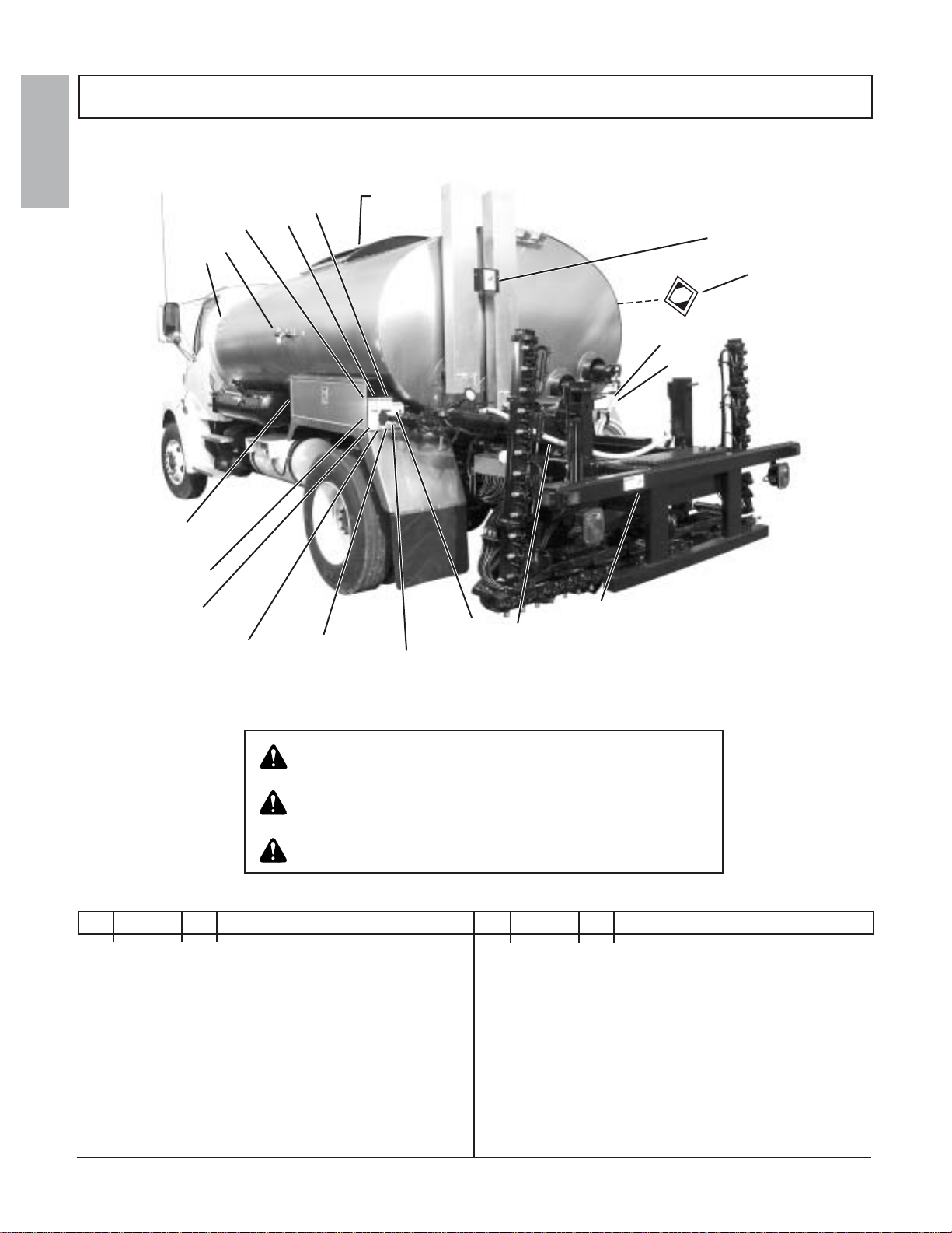
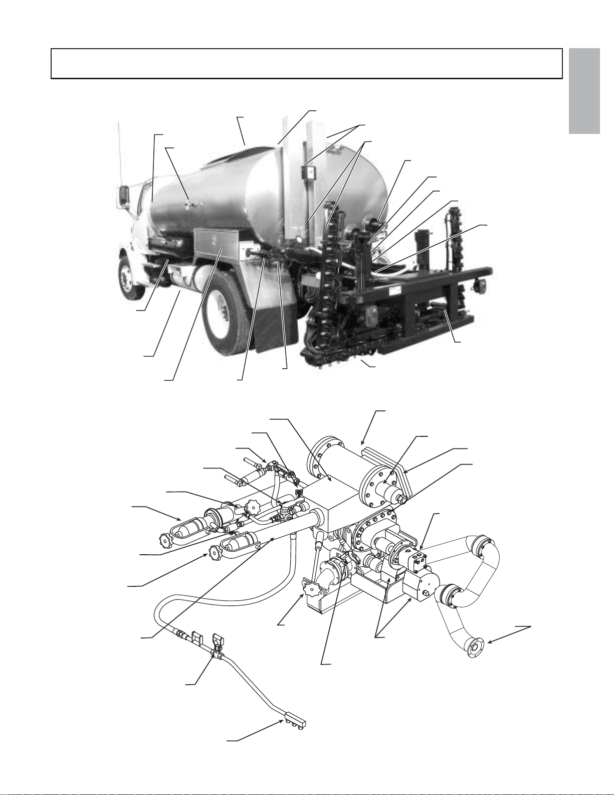
Component Location And Identification ............................9
Hydraulic Tank and Components ....................................10
Spray Bar Component Identification ...............................10
Cab Control Panel........................................................... 11
Rear Control Panel .........................................................13
Cationic Emulsions .........................................................14
Set up of the Computer ...................................................15
Preparing for Operation ..................................................15
Engaging Pump on PTO Equipped Distributors..............17
Foaming ..........................................................................17
Asphalt Institute ..............................................................17
Tank Capacity .................................................................18
Mixing Dow-Corning DC-200 Anti Foam Agent ...............18
Filling Through the Fill Line .............................................18
Connections and Preliminary Checks .............................18
General ...........................................................................19
Filling from the Cab .........................................................19
Filling from the Rear Control Panel .................................20
Filling through the Manhole.............................................21
Circulating Product in the Tank .......................................22
Circulating in the tank from the cab ................................22
Circulating in the Tank from the Rear Control Panel .......23
Circulating Product in the Bar .........................................24
Spraying Operations .......................................................24
Adjusting the Spray Bar Nozzle Angle ............................25
Adjusting the Spray Bar Height .......................................25
Spraying through the Bar ................................................25
Setting the Digital Memory Presets.................................26
Suckback from the Cab...................................................27
Handspraying ..................................................................28
Suck Back for Hand Spray Operations ...........................29
Pump Off Operations ......................................................30
Transfer Operations ........................................................31
Flushing Operations ........................................................32
HeatingAsphalt w/ Liquid Propane Gas (LPG) Burners...33
LPG Supply Tank Requirements .....................................33
Manual Control Burners ..................................................33
Burner Operation ............................................................33
Figure 15. Manual Control Burner System......................34
Burners With Outfire Controls .........................................35
Burner Operation with Outfire Controls ...........................35
Figure 16. Outfire Controlled Burner System ..................36
Burners with Automatic Ignition and Temperature Limiting
Control.............................................................................37
Burner Operation with Auto Ignition & Temp Control.......37
Electric Driven Burner Operation ....................................38
Troubleshooting ..............................................................39
Maintenance ...................................................................41
Electrode Assembly Adjustments ....................................41
Burner Air Band Settings.................................................41
Check Ignition Transformer Spark ..................................41
Fire Burners ....................................................................42
Adjusting Spray Bar Nozzle Angle ..................................42
Adjusting Spray Bar Height .............................................42
Servicing The Etnyre P-15 Pump....................................43
Vacuum Check ................................................................43
Pump Disassembly And Inspection.................................43
Impeller Installation And Pump Assembly .......................43
General Fuel Data And Heating Terminology.................44
Fuel Data.........................................................................44
Approximate Burner Fuel Consumption ..........................44
Low Pressure Fuel Oil.....................................................44
Kerosene Generating ......................................................44
Heating Terminology .......................................................44
Flash Point (Open Cup) ..................................................44
Closed Flash Point ..........................................................44
Fire Point.........................................................................44
Ignition Temperature
(Kindling Temperature)....................................................44
Convection ......................................................................44
Conduction ......................................................................44
Hydraulic Fluid Requirements .........................................45
General Information ........................................................45
Hydraulic fluid requirements ...........................................45
Viscosity & Temperature Requirements ..........................45
Contamination Levels .....................................................46
Lubrication Chart.............................................................47
Etnyre Spraybar Nozzles ................................................48

GENERAL
4
Warning And Instruction Plates
REF PART NO. QTY DESCRIPTION REF PART NO. QTY DESCRIPTION
For operator safety and possible liability protection, all Safety and
Instruction Plates should remain in place and be legible
Should a plate be removed, lost, or become illegible, reorder and replace
immediately
If plates become difficult to read because of material coating the surface,
clean with solvent
1 3390683 1 Plate- Caution, Shields in Place
2 3390681 1 Plate- Caution, Remain Clear of
3 3390682 2 Plate- Caution, Before Starting
4 3390686 1 Plate- Warning, Burner, General
5 3390679 2 Plate- Warning, Manhole
6 3390684 3 Plate- Caution, Hot Surface
7 3390696 2 Decal, BlackTopper Centennial
8 3390540 * Plate- Directions, LPG Burner
3390670 * Plate- Directions, Elect Beckett Burners
9 3390680 1 Plate- Warning, Fill Cap
10 3390685 1 Plate- Warning, Safety, General
11 3390592 1 Bracket- Mtg, Caution, Hot Surface
12 6100139 AR Rivet- Pop, 0.12, Not Shown
13 3390620 2 Plate- Warning, Manuals
14 6320056 AR Placard System (Optional)
15 3390636 1 Plate- Warning, Flues Covered
16 3390637 1 Plate- Warning, Asphalt Grades
17 3390655 1 Plate- Name, Distributor S/N, Brass
18 3390149 1 Plate- Name, Etnyre
19 3390591 1 Tag-Caution, Handspray Hose
20 3390659 1 Decal-Warning,GVWR
21 3390669 1 Decal-Handspray Operation
15 16
4
8
14
9
2
3
7
17
10
1
13
6
5,6
6,11
19
20
21

GENERAL
5
General Safety Instructions
The operation of a Bituminous Distributor normally requires handling of liquid products at elevated tempera-
ture. Also, these liquids may be of a volatile nature. A heating system is supplied to raise or maintain the product
temperature, and these systems use highly combustible fuels. As with any type of construction equipment, there are
certain hazards associated with careless or improper operation.
Safety warnings have been provided to call attention to any potentially hazardous situation that may cause
property damage, personal injury or death to the operator or bystanders. These safety warnings will be shown at
various times throughout this manual, as they are applicable to the subject being presented. These safety warnings are
identified by the following warning symbols:
Safety Precautions, Hazard Seriousness Level
You will find safety information boxes throughout this manual. These boxes contain information alerting you to
situations or actions to avoid.
Signal words (DANGER, WARNING and CAUTION) are used to identify levels of hazard seriousness. Their
selection is based on the likely consequence of human interaction with a hazard. Definitions of hazard levels are as
follows.
DANGER - Immediate hazards which will result in severe personal injury or death.
WARNING - Hazards or unsafe practices which could result in severe personal injury or
death.
CAUTION - Hazards or unsafe practices which could result in minor personal injury or prod-
uct or property damage.
All of these warnings are listed below and they also appear throughout the manual. In addition to these, you will
find notes throughout the manual.
NOTE - A note provides general information that the operator should be aware of when performing
an operation.
DANGER
To avoid an extreme fire hazard or explosion,
NEVER use gasoline as fuel in low pressure or
generating burners.
WARNING
A fully charged dry chemical type fire
extinguisher must be within easy reach
whenever the burners are operating or there is
an open flame near the distributor. The
minimum capacity of the fire extinguisher
should be 10 pounds.

GENERAL
6
WARNING
To prevent an explosion or fire hazard: Position
the unit broadside to the wind to prevent
volatile fumes from drifting toward the burners.
To prevent an explosion or fire hazard: Do not
operate the burners if the tank is damaged or
leaking
To prevent an explosion or fire hazard: Ensure
that the burners are extinguished before
removing any material from the tank in any
manner. Liquid petroleum (LP) burners can
support a flame for several minutes after the
fuel supply is turned off.
To prevent an explosion: Do not operate the
burners when the vehicle is unattended, when
the vehicle is in motion, or with the vehicle in a
confined area.
To prevent an explosion or fire hazard: When
the burners go out, shut off the fuel supply to
both burners and allow the flues to ventilate for
at least 3 minutes before re-lighting the
burners.
To prevent an explosion or fire hazard: Do not
heat the material beyond the manufacturer’s
recommended temperature.
To prevent an explosion or fire hazard: Keep
burning cigarettes or other sources of
combustion away from manholes and overflow
vents.
To prevent possible hand or facial burns:
Always light the inside burner first. Do not
reach across a lit burner to light or re-light the
inside burner. Shut off the outside burner
before lighting the inside burner.
To prevent possible burns: Always use a torch
to light the burners. Never attempt to light the
burners using a match or pocket lighter.
WARNING
To prevent an explosion or fire hazard: Check
the tank vent to insure that it is free from
obstruction before lighting the burners.
To prevent an explosion or fire hazard: Do not
operate the burners with the manhole open or
open the manhole while the burners are in
operation.
To prevent possible burns to operators or
bystanders, or possible equipment damage, do
not start any operation if any control settings
are unknown.
To prevent possible burns from leaking
material: Be sure all pipe, cap and hose
connections are secure before opening valves,
or beginning any operation.
To prevent possible burns from hot asphalt
spray: Do not stand, or allow anyone to stand,
where accidental opening of a valve may
cause contact with hot asphalt.
To prevent an explosion or fire hazard: Keep
area free of all sources of combustion when
spraying.
To prevent possible burns from foaming or
violent eruption, do not load tank with material
temperature over 200ºF if water or
condensation is present in tank, or if emulsion
was used in the previous load. Do not heat
material over 200ºF if moisture or emulsified
material is present in tank.
To prevent an explosion or fire hazard:
Eliminate sparks from engine exhaust.
To prevent burns from hot asphalt when
handspraying: Hold the handspray gun in
proper position and watch for other people.
To prevent burns: Always wear insulated
gloves when handling spray bar sections or
hoses.

GENERAL
7
WARNING
To prevent severe injury from becoming
entangled in machinery: Stand clear of rotating
drives.
To prevent possible injury: Always open the
manhole cover slowly. Pressure build up in the
tank may cause the cover to burst open.
To prevent possible fire hazards, burns or falls:
Keep the unit clean for safe operation.
To prevent possible burns from material
overflow: Allow sufficient space in the tank for
expansion of the material when heating
Before removing the fill line cap, make certain
that the asphalt pump is turning and the
suction valve is closed.
To prevent possible personal injury: Do not
load the vehicle beyond the GAWR or GVWR.
The maximum load volume must be calculated
based on material density
To prevent possible burns: Use extreme
caution when using a torch to heat the pump.
Asphalt accumulated around the pump may
ignite when heating the pump with a torch
Allowing the burners to operate for a long
period of time without circulating can damage
the product and create explosive fumes. If
product cannot be circulated after fifteen
minutes of heating without circulation, the
burners should be extinguished for 20 - 30
minutes before re-lighting the burners.
To prevent burns: Always wear eye protection,
long sleeve shirt, insulated gloves, boots, and
long pants outside the boots when working
around the distributor.
To prevent an explosion or fire hazard: Flues
,must be covered by a minimum 6 inches of
material (bitumen) when burners are in
operation
Use the measuring stick as shown in figure 1 to de-
termine the amount of product in the tank before light-
ingburners.The minimumamountsshown on the warn-
ing placard only apply if the tank is level. Remember
that the measuring stick is accurate only when the
tank is level. If the tank is not level, reposition the dis-
tributor to place the tank in a level position before tak-
ing final measurement. You must have at least the
amounts shown, with the tank level, in order to safely
light the lower burner and upper burner respectively.
Failure to have the appropriate amount, accurately
measured can result in an explosion causing death
or serious injury.

GENERAL
8
Introduction
Your Etnyre Blacktopper Shooter II Distributor is
designed to give you many years of accurate, depend-
able, and economic service. The following instructions
will enable you to receive the maximum performance
from your Blacktopper Shooter II Distributor.
TheBlacktopperShooterII Distributor’s controlsare
designedforsimpleoperation.They require a minimum
of training for proficient usage. The exclusive Etnyre
circulating system is designed and built for handling
all grades of bituminous materials efficiently.
This manual is provided as a tool to aid personnel in
the operation of the Etnyre Blacktopper Shooter II Dis-
tributor in a safe and efficient manner,As with any type
of construction equipment, there are certain hazards as-
sociated with improper or careless operation. The abil-
itytoread and understand theinstructionsin this manual
should be a required qualification to become an opera-
tor. There are also functions that require a certain
amount of physical strength to accomplish. Persons
lacking the required strength may not only place them-
selves in jeopardy, but also others in the vicinity.
This manual covers standard features and options
for truck mounted units with computerized controllers
only. If your unit incorporates custom features, some
of the information contained in this manual may not
apply. If you have any questions regarding this manual
or your unit, contact your Etnyre dealer or the E. D.
Etnyre Service Department at 1-800-995-2116.
CAUTION
Unusually strong electromagnetic interference
could cause the electronic controls on this
equipment to temporarily malfunction. Test the
effect of two way radios and similar equipment
while operating in a safe area.
Reporting Safety Defects
If you believe that your vehicle has a defect which
could cause a crash, or could cause injury or death, you
should immediately inform the National Highway Traf-
fic Safety Administration (NHTSA) in addition to no-
tifying E. D. Etnyre & Co.
If NHTSA receives similar complaints, it may open
an investigation; and, if it finds that a safety defect ex-
ists in a group of vehicles, it may order a recall and
remedy campaign. However, NHTSA cannot become
involved in individual problems between you, your
dealer, or E. D. Etnyre & Co.
To contact NHTSA, you may either call the Auto
SafetyHotlinetollfree at 1-800-424-9393 (or 336-0123
in the Washington, D.C. area). or write to NHTSA, U.S.
DepartmentofTransportation,Washington, DC, 20696.
You can also obtain other information about motor ve-
hicle safety from the hotline.

GENERAL
9
Component Location And Identification
4 Way Valve
Rotary Actuator
Suction Screen
Optional Front Suction Valve
(not shown)
Rear Suction Valve
Asphalt Pump
Drive Motor
Spray Bar
Feed Tube
Asphalt Pump
Hand Spray Gun
Suck Back Valve Control
Butterfly Valve Control
Strainer/Valve Box
Handspray Suck Back Valve
Transfer Valve
Transfer Line
Transfer Line
Suck Back Valve
Return
Valve
Fill Line
Fill Line Strainer
Flushing System Valve
Hand Spray Valve
Spray Bar Wing
Lift Cylinder
Spray Bar
Asphalt Pump
Strainer/Valve Box
Rear Suction Valve
Burners
Exhaust Stack Damper
Exhaust Stack
Manhole
Tank Gage
Tool Box and
Rear Control Panel
Fuel Oil Tank
(Hydraulic Oil
Tank on Right
Side of Frame)
LPG Tank
Pump Off Line Fill Line
Return Valve
Thermometer
Ladder on Right Side

GENERAL
10
Component Location And Identification
One Foot Controls (standard)
Air cylinders on spraybar are individually controlled by
switches in the cab control panel. Each cylinder controls
on/off of 3 spray bar valves (one foot of spray). Flip levers
on valves allow manual control of individual valves.
1. Hydraulic Filter
2. Thermo Switch
3. Hydraulic Oil Specifications
Instruction Plate
4. Mounting Bracket
5. Hydraulic Tank Assembly
6. Breather
7. Fill Cap
8. Pipe Plug
9. Thermometer
10.Oil Eye Sight Plug
4
1
15
6
7
8
8
9
2
3
10
4
Spray Bar Component Identification
Hydraulic Tank and Components
Right Wing Section
with Spray Valves
Left Wing
Section
8' Center Section
with Valves and
Nozzles
Spray Bar
Feed Tubes Spray Valve
Flip Lever
Breakaway
Swivel Joint
Nozzle

GENERAL
11
Cab Control Panel
1. Spray Bar Switch
Turns all activated spray bar valves On or Off.
2. Hydraulic Oil Temperature Warning Light
Indicates that at the hydraulic oil temperature has
exceeded 180ºF. Stop immediately and determine the
cause of the high temperature. Failure to do so will re-
sult in damage to hydraulic components.
3. PTO Indicator Light
Indicates PTO engagement for units equipped with
a PTO driven hydrostatic pump.
4. Low Tank Level Indicator Light
Indicates low material level in the tank when lit.
5. Power Switch
Controlspowerto both the front andrearcontrol pan-
els,eitherOn or Off. Both the frontandrearpanel power
switches must be on to operate the distributor.
6. Bar Shift Switch
Moves the entire Spray Bar left or right. It is part of
the power lift, shift and wing fold option.
7. Bar Lift Switch
This switch raises and lowers the bar to the lower
barstopsand the upperpositionwhere it may belatched.
It is part of the power lift, shift and wing fold option.
8. Wing Fold Switches
Raise and lower the left and right wings. They are
also part of the power lift, shift and fold option. It is
possible to have three separate folding sections on each
wing. If you only have one folding section on a side
you will only have one switch per side, and so on.
9. Digital Display Screen
The digital display shows the application rate in gal-
lons/sq yd on the upper line of the display. The lower
line shows the speed in fpm on the left side and the
pump rate in gpm on the right side. Pushing the change
display button once will move you to the next screen
which shows the feet of bar selected, feet traveled and
the gallons sprayed since the last time the reset gallons
button or reset feet button was pushed. Pushing the
change display button again will move you to the next
screen which displays the sq. yd. shot since the last time
the reset buttons were pushed simultaneously. Pushing
the change display button again will move you to the
next screen which displays the material temperature
(optional).Pushing the change display buttonagainwill
move you to the next screen which displays the start
up factor. The start up factor sets how the spray bar
will act when it is first turned on. It is adjusted using
the Application Rate switch. The start up factor is nor-
mally set at 100% from the factory. If the start is thin or
weak, you can increase the start up factor to compen-
sate for this.A higher number will make the beginning
of the shot more aggressive or fatter. You may have to
change the start up factor by as much as 25 to 30% to
see the appropriate change. Conversely if the start of
the shot is too fat and heavy you would have to de-
crease the start up factor by as much as 25 to 30% to
get it where you want it.You can then make some finer
R
HYD OIL
HYD OIL
PT
PT
OLOW
LOW
TANK LEVEL
ANK LEVEL
FRONT
FRONT
REAR
REAR
SUCTION
SUCTION
3361133G
SHIFT
SHIFT
LIFT
LIFT
WING FOLD
WING FOLD
12345
CHANGE
CHANGE
DISPLA
DISPLA
Y
RESET
RESET
GALLONS
GALLONS
LITRES
LITRES
RESET
RESET
FEET
FEET
METRES
METRES
ON
OFF
ON
OFF
APPLICA
APPLICA
TION
TION
RA
RA
TE
TE
POWER
POWER
CIRCULA
CIRCULA
TION
TION
RA
RA
TE
TE
SPRA
SPRA
YBAR
YBAR
MEMOR
MEMOR
Y
MAIN BAR
MAIN BAR
LEFT WING
LEFT WING
RIGHT WING
RIGHT WING
TEMP
TEMP
43211234
CIRC. IN TANK LOAD
SUCK BACK
CIRC.
IN BAR
MARKER 12 11 10 9 8 7 6 5 56789101112MARKER
SUCKBACK
SUCKBACK
BAR
BAR
CENTERED
CENTERED
ON
ON
OFF
OFF
ON
ON
OFF
OFF
MIRROR
MIRROR
BAR LA
BAR LA
TCH
TCH
1
2
3
4
5
6
7
88
9
10
11
12
13
13
14
151516 17
18
20
22
23
21
Component Location And Identification
CAB CONTROL PANEL

GENERAL
12
adjustments once you get it close to what you desire.
Pushing the change display button again will move you
to the next screen which displays the minimum pump
speed. The minimum pump speed should be set to 0
using the application rate switch. When the minimum
pump speed has been set, depress the reset gallons but-
ton to move to the next screen. The display can also be
changed to show all of the above items in metric units
if so desired. See the part of the manual on screen set
up for a description of how to do this.
10. Circulation Rate Switch
This switch controls the speed of the asphalt pump
for all functions requiring circulation or transfer of
material except spraying. You should select the spray
bar length to be used before setting the circulation rate.
When spraying (the spray bar switch is on), the asphalt
pumpiscontrolled by the setting oftheApplicationRate
switch. To increase the circulation rate, hold the Circu-
lation Rate switch up, and to decrease the circulation
rate, hold the Circulation Rate switch down. Holding
the switch up or down for more than a 5 seconds, causes
the circulation rate to change faster. The last number to
appear on the digital screen immediately after releas-
ing the circulation rate switch will be the set point.
11. Reset Feet Button
This button resets the feet traveled count to zero. It
can be used after each shot if so desired or at the end of
the day’s work.
12. Suction Switch
This switch is used to select the use of the optional
front suction valve instead of the rear suction valve.
This switch is only installed on distributors which have
the optional front suction valve installed.
13. Bar Selector Switches
These switches actuate each individual foot of spray
bar for control of which parts of the spray bar will open
when the spray bar switch is turned on. In the up posi-
tion, the selected foot of spray bar will come on when
the spray bar switch is turned on. The computer will
automatically change the pumping rate whenever a
switch is turned on or off while spraying, to compen-
sate for the shorter or longer number of feet being
sprayed. These switches are only installed when the
distributor is equipped with the one foot control op-
tion, and then only for the number of feet of bar origi-
nally installed at the factory.
14. Rotary Actuator
This knob is for the optional cab control of the 4-way
valve and the suction valve at the rear of the distributor.
15. Memory Buttons
The computer can store 5 different application rates
in internal memory. In order to program a button you
must hold the button down while adjusting the applica-
tion rate using the application rate switch. Once the
application rate is stored in a location, you merely need
to tap the appropriate button to bring it back to use.
16. Change Display Button
Thisbuttonchanges the display through the5screens
of information available. (6 screens if the temperature
option is on the machine.) The normal operating screen
shows gal/sq yd, fpm and gpm. Depressing the button
once will take you to the next screen, feet of bar, feet
traveled and gallons sprayed. Depressing the button
once again will take you to the next screen, sq yd shot,
temperature in ºC, temperature in ºF (optional). De-
pressing the button once more will take you to the start
up factor screen. Depressing the button again will bring
you to the minimum pump speed screen. Depressing
the button once more will bring the main operating
screen back up.
17. Reset Gallons Button
This button resets the gallons sprayed count to zero.
It can be used after each shot if so desired or at the end
of the day’s work. The total square yards is reset to
zero by depressing the reset gallons and reset feet but-
tons down simultaneously.
18. Application Rate Switch
This switch is used to set the application rate for
spraying. This switch is also used to change other func-
tions while in screen other than the main operator scree,
20. Suckback Switch
This switch selects the suckback function. Hold the
switch Up to activate suckback and release to have nor-
mal operation. (optional)
21. Bar Latch Switch
This is part of the power bar latch option. Push up to
latch the bar in its transport position and push down to
release the bar so that it can be lowered to its spray
position. If your Distributor is not equipped with this
option, this switch will not be there.
22. Mirror Switch
This switch controls the optional electrically adjust-
able mirror. Push up to raise the mirror and down to
lower the mirror. Push left to rotate the mirror to the
left and push right to rotate the mirror to the right. If
your Distributor is not equipped with this option, this
switch will not be there.
23. Bar Centered Light.
This light is part of the lift shift and raise option and
shows when the spraybar is centered. If your Distribu-
tor is not equipped with this option, this light will not
be there.

GENERAL
13
Component Location And Identification
REAR CONTROL PANEL
Rear Control Panel
1. Pump Control Knob
Thisknobcontrols thespeedoftheasphaltpumpwhen-
ever the pump control switch is in the rear position.
2. Pump Control Switch
This switch selects which pump control is connected
to the pump. In the front position, the cab mounted con-
trol is active, while in the rear position, the pump con-
trol knob adjacent to the switch is connected to the
pump. Be sure to select the front position before get-
ting into the cab.
3. Suction Valve Switch
This switch turns the selected suction valve on or off.
4. Bar Shift Switch
This switch moves the spray bar left and right. It is a
part of the power lift, shift and raise option. If your
Distributor is not equipped with this option, this switch
will not be there.
5. Bar Lift Switch
This switch moves the spray bar up to the latch posi-
tion and down to the spray position. It is a part of the
power lift, shift and raise option. If your Distributor is not
equipped with this option, this switch will not be there.
6. Wing Fold Switches
Theseswitchesraise andlowerthe right andleftspray
bar wings. It is possible to have three separate sections
on each wing so the panel is set up for that. They are
part of the power lift, shift and raise option. If your
Distributor is not equipped with this option, these
switches will not be there. If you have single folding
wing sections, there will only be one switch per side.
7. Burner Power Switches
These switches apply power to drive the burner
blowers and start the burners. Before operating the
burners, refer to the portion of the manual which ex-
plains the burner operation.
8. Bar Latch Switch
This switch operates the power bar latches for travel.
This is a separate option. If your Distributor is not
equipped with this option, this switch will not be here.
9. Washdown Switch
This switch activates the pump for power washdown.
Whenthepumpisturnedon,theindicator lightandbuzzer
will be on. This is a separate option. If your Distributor is
notequipped withthisoption,thisswitch willnot behere.
10. Master Power Switch
This switch turns the power to the front and rear con-
trol panels on or off. Be sure to turn this switch off at
the back of the distributor when you are finished, to
guard against movement by untrained personnel. Since
all power is disabled by this switch it can also be used
as an emergency shutdown switch
11. Suckback Switch
This switch selects the suckback function. Hold the
switch Up to activate suckback and release to have nor-
mal operation. (optional)

GENERAL
14
NOTICE
The handling of Cationic Emulsions (CRS-2, CMS-2, CSS-1 and CSS) may
create an environment within the Asphalt Distributor that can be corrosive to
carbon steel and cast iron.
•Cationic Emulsions are widely used within the industry.
•Cationic Emulsion is manufactured with asphalt, water, emulsifiers and
hydrochloric acid. The chemistry of individual emulsions varies in asphalt
content and Ph levels.
•Tanks and spray mechanisms used with Cationic emulsions may experience
corrosion
•It is believed the chemistry of the emulsion - specifically the residual fumes
promote the corrosion
• Etnyre Distributors are compatible with Cationic Emulsions provided that
certain precautions are taken.
•Prior to placing a distributor in to service with Cationic Emulsion, it should be
loaded with an AC or MC type material to develop a protective coating.
• Periodic inspection of the tank and spray system should be preformed in the
normal course of operation.
• It is recommended that distributors used in Cationic service be flushed
periodically and at the end of the season with an AC, MC or cutback to
remove the corrosive materials and to provide a protective coating.
•Increasing the quantity of flushing material during daily suck back and
cleanout operations will also help to minimize corrosion damage.
•Dilution is the solution.
• Additional information can be acquired from your Emulsion supplier as well
as the Asphalt Institute or the Asphalt Emulsion Manufactures Association.
WARNING
Take extra care and follow recommended
procedures when alternating asphalt materials
especially when loading hot product, over 212
degrees Fahrenheit (100 degrees Celsius), on
to a tank and system previously in Emulsion
service.
Cationic Emulsions

GENERAL
15
Always refer to the truck chassis owner’s manual
for chassis and engine maintenance information.
The following procedures apply to new or rebuilt
units.
1.Inspectthe unit for damagethatmayhave occurred
during transporting.
2. Check and tighten all fasteners, body tie-down
bolts, pipe and circulating line connections, etc. that
may have loosened in transit.
3. Check the fluid level in the hydraulic reservoir.
The fluid must always be visible in the sight glass.
WARNING
To prevent becoming entangled in machinery
remain clear of rotating drives.
Set up of the Computer
There are 10 screens which have to be set to match
the options of the particular Shooter II Distributor that
the computer control is installed in.
To enter the set up screens hold the reset gallons
button down while turning on the master power switch.
After turning on the master power switch, release the
reset gallons button. The first screen is the circulation
rate screen, however, the S2X computer will bypass
this and go to the second screen. To see this screen you
have to toggle through all of the other screens. To step
through the screens, push the reset gallons button. To
change the set up, follow the instructions that appear
on the screen; push the application rate switch up or
down, as instructed. When done, save the settings as
instructed on the screen.
First screen:Circulate Rate Adj
XXX Gal/Min
This screen shows the current setting of the circula-
tion rate in GPM or LPM depending on whether the
display is set to English or Metric units.
Second screen:
Flow Cal Factor
1000
The factory setting should be 1000 (100%). The
pump calibration can be changed by 0.1% increments
byusingthe application rate switch. Increasingtheflow
factor increases the reading for a given flow-not the
Preparing for Operation
flow. Decreasing the flow factor decreases the reading
for the given flow. Use the application rate switch to
change. Only make a change is you are absolutely sure
that the calibration is incorrect.
Third screen:
Speed Cal Factor
100
This screen shows a ground speed radar calibration
factor. The factory setting should be 100. The ground
speed calibration can be changed in 1% increments. By
changing this factor. Increasing the speed factor will
increase the reading for a given speed and decreasing
the speed factor will decrease the reading for a given
speed. Use the application rate switch to change.
Fourth screen:
English Units
Decrease to Change
This screen allows you to change the display units
to Metric or English. Push the application rate switch
down to change to Metric units and if it is set to Metric
units, push the application rate switch up to change to
English units.
Fifth screen:Series 42 Pump
Increase to Change
This screen sets the type of hydrostatic pump that
the machine has. Push the application rate switch up to
change to the 90 Series and push the application rate
switch down to select the 42 Series.
Sixth screen:1 ft controls
Decrease to Change
This screen selects between 1 foot controls or gang
bar controls. Push the application rate switch down to
change to gang bar. If the control is set to gang bar
control push the application rate switch up to change
to 1 ft controls.
Seventh screen:
Pulses/Gallon Adjust
164
This screen allows for changing thenumber of pulses
per gallon being fed to the computer. This number
should be set to 164 for a 42 Series pump. Use the ap-

GENERAL
16
plication rate switch to set this number. 309 is the de-
fault
Eighth screen:
Threshold Adjust
16
This screen allows for adjusting the target current
for the start of spraying. This number can be adjusted
up or down. A higher number will give a more ag-
gressive start when the master spray switch is turned
on.Alower number will give a more gentle start. The
number on each distributor needs to be set to match
the current in milliamps that is required to just start
theasphaltpump turning. Refer toengineeringinstruc-
tion #9100411 or the service video for detailed in-
structions on how to find the right value for the thresh-
old.
Ninth screen:
1.00 to 1 Ratio
This can be changed using the application rate
switch. 4.39 is the default.
Tenth screen:
Relay Time Delay
0.2
Sets the spray delay to allow for the 4-way valve
to be moved before opening the spray nozzle valves.
The spray delay should be set to 0.2 seconds using
the application rate switch.
Eleventh screen:
EXIT=PUSH APP INC
SAVE=PUSH APP DECR
This screen allows you to return to the operating
mode, or saving the setting and returning to the oper-
ating mode. Push down and hold the application rate
switch to save the settings. When the screen changes,
release the switch. Push up to exit without saving.
WARNING
To prevent severe injury from becoming
entangled in machinery: Stand clear of
rotating drives
WARNING
To prevent possible burns to operators or
bystanders, or possible equipment damage,
do not start any operation if any control
settings are unknown.
CAUTION
To prevent damage to the asphalt pump, do not
run pump for more than 5 minutes without
bitumen to supply lubrication

GENERAL
17
Engaging Pump on PTO Equipped
Distributors
Before getting into the cab, check to make sure that
the front/rear pump control switch on the rear control
panel is in the forward position.
Start the truck engine with the transmission in neu-
tralandengagethePTO.Ontruckswitha manual trans-
mission, depress the clutch and pull outward or upward
on the PTO control knob. Slowly let the clutch up, if
the PTO fails to engage, depress the clutch pedal and
pull up on the PTO handle until engagement occurs.
Or, depress the electric air shift PTO switch if your
vehicle is so equipped. Increase the engine rpm to a
fast idle.
Ontruckswith an automatictransmission,push down
on the foot brake pedal, move the gear selector to any
forward gear and pull upward or outward on the PTO
controlknob.Or depresstheelectric air shiftPTOswitch
if your vehicle is so equipped. When the PTO engages,
move the gear selector to neutral.
If the PTO fails to engage, continue pulling on the
knob while releasing the brake pedal slightly, allowing
the truck to inch forward until the PTO engages and
then move the gear selector back to neutral.
Ensure that the truck parking brake is engaged be-
fore leaving the cab.
WARNING
To prevent an explosion or fire hazard: Do not
heat the material beyond the manufacturer’s
recommended temperature.
CAUTION
To prevent possible damage to equipment from
material setting up in hose or distributor,
ensure that bitumen in supply tank is heated
sufficiently.
WARNING
To prevent possible burns: Use extreme
caution when using a torch to heat the pump.
Asphalt accumulated around the pump may
ignite when heating the pump with a torch.
Foaming
If the distributor is to be filled with hot bitumen,
proceed very cautiously. If there is any moisture in the
tank, or if an emulsion product was the last load, foam-
ing or eruption may occur.
Dow-Corning DC-200 may be used to prevent foam-
ing in Distributors, Transports, and Maintenance Units.
Mix the contents of one can (16 oz.) with one (1)
gallon of diesel fuel or kerosene. Add one (1) oz. of
this diluted mixture to each 1000 gallons of asphalt.
The correct amount may be poured through the man-
hole. This will assist in reducing foaming, particularly
if moisture is present or if an emulsified asphalt was
used in a previous load.
If foaming does not occur at the start of the filling
operation, but you suspect that there may be moisture
in the spray bar or circulating system, the filling opera-
tion should be stopped when the tank is no more than
25%full.The product shouldthenbecirculatedthrough
the spray bar at a rate of 80 to 100 GPM before con-
tinuing the filling operation.
If foaming does occur, continue circulating until the
foaming stops, and then suck back the product in the
spray bar back into the tank before filling the tank the
rest of the way.
Asphalt Institute
To further increase awareness of the hazards associ-
ated with the operation of a bituminous distributor, and
before beginning initial operation, the operator should
also receive instruction by an authorized Etnyre dealer,
or Etnyre representative.
The Shooter II Distributor is designed to handle a
number of different products, such as AC’s, cutbacks
& emulsions.
Knowledge of these liquid asphalts is required for
safe operation of the distributor. It is critical to know
which product can be loaded after the previous prod-
uct, and which products react with each other.
TheAsphalt Institute is a source of asphalt handling
safety information.
Asphalt Institute
Research Park Drive
PO Box 140052
Lexington, KY 40512-4052
606-288-4960

18
OPERATION
Tank Capacity
The Shooter II Distributor is designed to pump and
spray a variety of asphalt products in an efficient and
user friendly manner with great accuracy. The Shooter
II Distributor utilizes a computer to sense the vehicle’s
ground speed and control the hydrostatically driven
asphalt pump to maintain the set application rate, re-
gardlessofvariations in vehiclespeedor spray barwidth
in use.
For a complete description of each of the controls
and how to set up the machine, refer to the set up sec-
tion of this manual.
WARNING
To prevent possible personal injury: Do not
load the vehicle beyond the GAWR or GVWR.
The maximum load volume must be calculated
based on material density
The Shooter II Distributor tank has a built-in air
space, or expansion space, above the “Tank Full” level.
This air space is designed to minimize the chance that
the tank will overflow if the material in the tank ex-
pands due to heating or foaming. This air space should
not be used to carry product. The “Tank Full” level is
based on the vehicle’s axle ratings, and, GVWR at a
material density of 7.7 lbs/gallon. A lower “tank full”
must be calculated if a product with a density greater
than 7.7 lbs/gallon is to be loaded. The lower “tank full”
is calculated by multiplying the original “tank full” by
7.7 and dividing the result by the new heavier product
density.
If you suspect there may be moisture or emulsion in
the tank, Dow-Corning DC-200 additive can be used
to reduce foaming if a product being pumped is at a
temperature in excess of 200ºF.Additional DC-200 ad-
ditive may be obtained from E. D. Etnyre & Co. or
your Etnyre dealer.
Mixing Dow-Corning DC-200 Anti Foam
Agent
Mix the contents of one can (16 oz.) with one (1)
gallon of diesel fuel or kerosene.Add one (1) ounce of
this diluted mixture to each 1000 gallons of asphalt.
The correct amount may be poured through the man-
hole. This will assist in reducing foaming, particularly
if moisture is present or if an emulsified asphalt was
used in a previous load.
Ifyoususpectthatthere may be moisture in the spray
bar or circulating system, the filling operation should
be stopped when the tank is no more than 25% full.
The product should then be circulated from the tank
through the spray bar for a minimum of 2 minutes at a
rate of 80 to 110 GPM before continuing the filling
operation. After circulating product in the spray bar,
suck back the material from the bar and then return to
the loading configuration and continue loading.
If foaming does occur, continue circulating until the
foaming stops, and then suck back the product from
the spray bar into the tank before continuing the load-
ing operation.
Filling Through the Fill Line
WARNING
To prevent possible burns from foaming or
violent eruption, do not load tank with material
temperature over 200ºF if water or
condensation is present in tank, or if emulsion
was used in the previous load. Do not heat
material over 200ºF if moisture or emulsion is
present in tank.
Connections and Preliminary Checks
WARNING
To prevent possible burns from leaking
material: Be sure all pipe, cap and hose
connections are secure before opening valves
or beginning any operation.
WARNING
To prevent possible burns to operators or
bystanders, or possible equipment damage,
do not start any operation if any control
settings are unknown.
General

19
OPERATION
WARNING
To prevent an explosion or fire hazard: Keep
burning cigarettes or other sources of
combustion away from manholes and overflow
vents.
WARNING
To prevent burns: Always wear eye protection,
long sleeve shirt, insulated gloves, boots, and
long pants outside the boots when working
around the distributor.
Ensure that both the fill line and the suction strain-
ers are clean and properly installed.
Ensure that all connections between the distributor
and the supply source are tight to prevent asphalt leaks.
Air leaks will reduce the vacuum and slow down the
filling operation. The distributor is designed to suck
asphalt through the fill line. Do not pressurize the fill
line with an external pump.
WARNING
Before removing the fill line cap, make certain
that the asphalt pump is turning and the
suction valve is closed.
Filling from the Cab
If you have not yet done so, read “Filling through
the fill line” before continuing.
1. Set all of the valve positions first. (See Fig 2)
2. Be sure that the master power switch is in the off
position to insure that nothing can function while
switches are being set.
3. Turn the “Spray Bar” switch “off” to insure that
the spray bar valves remain closed when the “Master”
switch is turned back on..
4. The optional Front/Rear “Suction” switch can be
in either position.
5. Turn the “Rotary Actuator” knob to the “Load/
Suckback” position. This positions the 4-way valve in
the “Load” position.
At the rear panel:
Place the “Pump Control” switch in the “front” po-
sition. This disables the rear panel pump control and
makes the front panel pump control active.
Place the “Suction Valve” switch in the closed posi-
tion. This insures that the pump will not remove any Figure 1 Using the Measuring Stick
material from the tank.
Turn the “Master Power” switch “on” to enable the
front control panel.
6. At the cab panel, turn the “ Power” switch “on”.
Both the front and rear power switches must be on to
operate.
7. Set the digital display to “GAL/SQ. YD; FPM;
GPM” by using the “Change Display” button so you
can see the pumping rate displayed.
8. Run the engine at a minimum of 1100 RPM.
WARNING
To prevent possible burns from material
overflow: Allow sufficient space in the tank for
expansion of the material when heating
9. Toggle the “Circulation Rate” switch up or down
to obtain the desired rate. A pump rate of 75 GPM is
recommendedtobegin the loading operation.The pump
rate can be increased at any time after loading has be-
gunbyusingthe circulation rate toggle switch. Depend-
ingonmaterial viscosity,asthe loading rateisincreased,
the asphalt pump may cavitate. When this happens, the
pump will make a distinctive sound, easily recognized
with experience. Short periods of operation while the
pump is cavitating will not damage the pump but you
should not operate the pump in this condition for ex-
tended periods. Higher speeds will not load thick ma-
terial faster. Light materials or materials at spraying
temperature, may be loaded at faster pump speeds.
00
100
"0"
End of stick touches
top of oil
Read amount of
material in tank
at top edge of
manhole ring
Full
Using the Measuring Stick
The measuring stick is only accurate when the tank is level.
Table of contents
Other Etnyre Utility Vehicle manuals

Etnyre
Etnyre Black-Topper User manual

Etnyre
Etnyre M-752-02R1 User manual

Etnyre
Etnyre Black-Topper CENTENNIAL S-2000 Series Service manual

Etnyre
Etnyre Black-Topper CENTENNIAL User guide

Etnyre
Etnyre Centennial A-130-12R User manual

Etnyre
Etnyre Black-Topper User manual

Etnyre
Etnyre Street Flusher Instruction Manual

Etnyre
Etnyre Black-Topper BT-1 Distributors 2008 Technical manual

Etnyre
Etnyre BLACKHAWK RTN Series User manual

Etnyre
Etnyre Black-Topper SHOOTER Series User manual