EtroVISION EV6356A User manual

EV6356A
IR Outdoor IP Camera
Installation Guide – Version 6.2

About This Guide
Model
EV6356A-BO
EV6356AP-BO
EV6356A-CO
EV6356AP-CO
Before Using the EV6356A IR Outdoor IP Camera
Check the PC requirements
Review the OS platform requirements
Install EtroStation™ 3.0 software before you start using the video server.
Read any special and important precautionary information.
Having a basic knowledge of network setup and configuration will be helpful.
Icon Descriptions
Notes: This icon represents a tip for operation.
Caution: This icon stands for an action that probably impairs the
operation.
Warning: This icon stands for an action that can cause damage to the
system.
Disclaimer
© 2007 Etrovision Technology. All rights reserved.
EtroLink™ & AnyUSB™ are trademarks of Etrovision Technology; other product
or service names mentioned herein are the trademarks of their respective
owners. Information contained in this document may be superseded by updates.
No representation or warranty is given and no liability is assumed by Etrovision
Technology with respect to the accuracy or use of the information, or
infringement of patents or other intellectual property rights. No licenses are
conveyed, implicitly or otherwise, under any intellectual property rights.

TABLE OF CONTENTS
1PRODUCT OVERVIEW............................................................................5
1.1 Product Specifications..............................................................................................................5
1.2 Dual Streaming Capabilities....................................................................................................7
1.3 Model Differences.....................................................................................................................7
1.4 Package Checklist.....................................................................................................................8
1.5 Product CD...............................................................................................................................8
1.6 Language Support....................................................................................................................8
1.7 Front and Side Camera Views.................................................................................................9
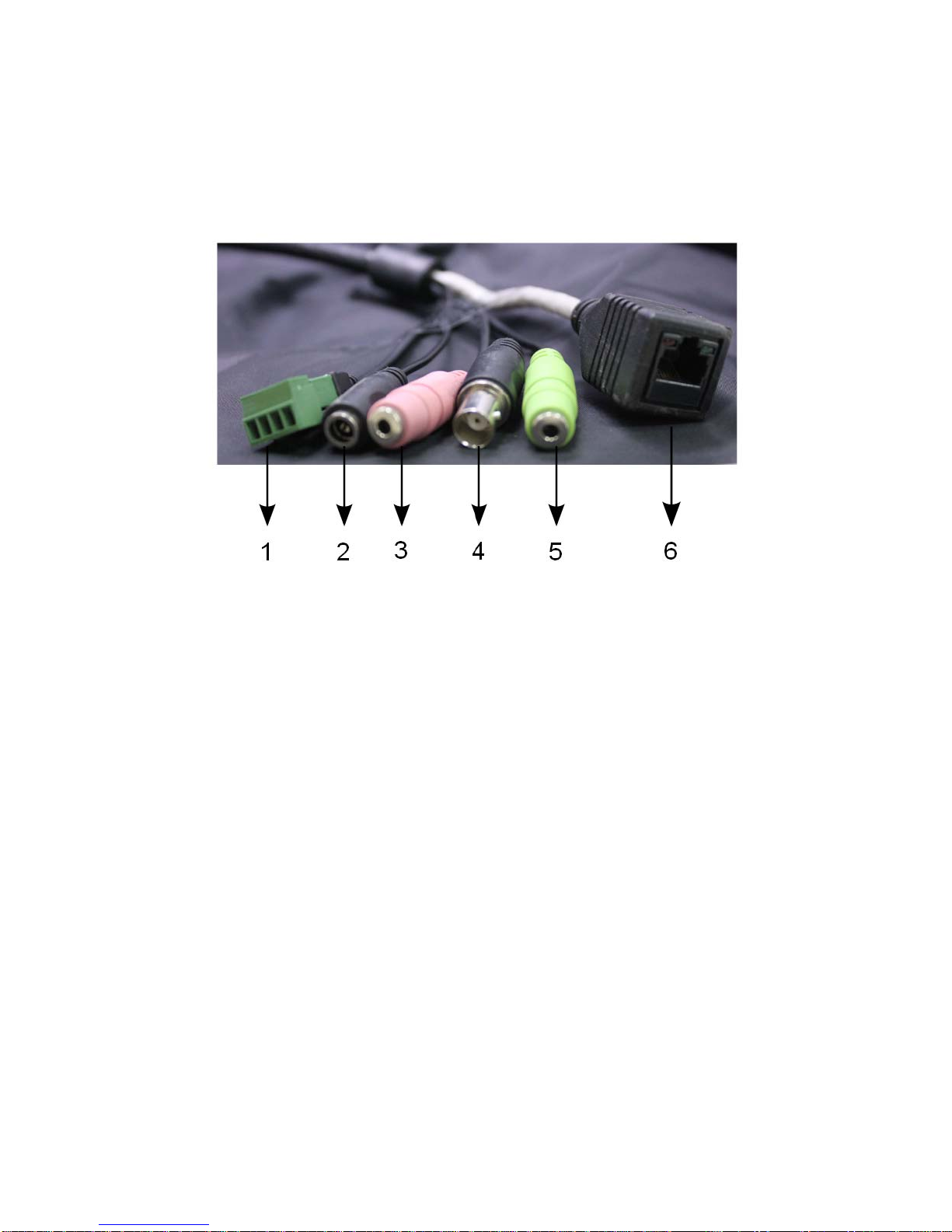
1.8 Physical Connections .............................................................................................................10
2USING THE EV6356A FOR THE FIRST TIME ......................................11
2.1 Initial Requirements ..............................................................................................................11
Software Requirements...................................................................................................................... 11
Install EtroStation™ 3.0 .................................................................................................................... 11
2.2 Physical IPCamera Connections..........................................................................................12
Connect to the Network .....................................................................................................................12
Connect Digital I/O............................................................................................................................12
Connect Audio I/O.............................................................................................................................12
Connect Video Out ............................................................................................................................12
Power on IP Camera ..........................................................................................................................12
2.3 Initial Network Configuration ..............................................................................................13
Factory IP Address.............................................................................................................................13
Alter the Network Domain ................................................................................................................13
Using EtroScan™ ..............................................................................................................................14
Change Network Setting via EtroScan™...........................................................................................16
2.4 Access the IP Camera Web Interface....................................................................................19
3ETROLINK™ CONFIGURATION PORT................................................22
3.1 OS Requirements ...................................................................................................................22
3.2 Setup Using the EtroLink™ Config Port.............................................................................22
Connecting the IP camera to the PC ..................................................................................................23

Quick Config Login...........................................................................................................................24
Quick Wizard - Network....................................................................................................................25
Manually Starting the Quick Config Wizard .....................................................................................27
3.3 Factory Default.......................................................................................................................28
4ADDITIONAL INFORMATION................................................................30

1 PRODUCT OVERVIEW
The EV6356A IR Outdoor IP Camera is a professional, IP66 waterproof camera with
12 piece IR LED providing 35M coverage. In addition to being durable, the EV6356A
offers PoE support. With H.264 compression technology, the EV6356A delivers
superior image quality while minimizing bandwidth requirements.
1.1 Product Specifications
EV6356A-BO EV6356AP-BO EV6356A-CO EV6356AP-CO
Sensor 1/3" Sony CCD Sensor
Lens External Adjustable Varifocal Lens
/ Auto Iris 3.8-9.5mm
External Adjustable Varifocal Lens / Auto
Iris 9-22mm from Outside
Auto Control BackLight Compensation / Gain Control / White Balance
Number of Effective
Pixels (HxV)
811 x 508 (NTSC) ,
795 x 596 (PAL)
Electronic Shutter NTSC: 1/60-100,000 sec , PAL: 1/50-100,000
Iris Auto Iris
Gain Auto
Lens / Sensor
White Balance Auto
Built-in IR LED 12pcs High-Light LED
IR Wavelength /Beam
Angle
850nm
IR View Angel View Angle:50~180°, Beam Spread:30°/per LED
IR LED
Max. IR Range 35 Meter
Horizontal Resolution 420 TVL 520 TV lines
S/N Ratio More than 50dB (AGC Off)
Analog Video
Output Minimum Illumination 0.06 Lux / 0 Lux (IR LED On)
CPU ARM 9 Based 32 bit RISC
SDRAM 128 MB
Flash 16 MB
System
Embedded OS Linux 2.6
Compression– Format H.264, M-JPEG, MPEG-4 Dual Stream

Frame Rate Up to 30fps (NTSC) / 25fps (PAL) @ D1 Resolution
NTSC: D1 (720x480), CIF(352x240), QCIF(176x120)
Video Resolution PAL: D1 (720x576), CIF(352x288), QCIF(176x144)
Bit Rate M-JPEG: 5 Video Quality Level Selectable; MPEG-4/H.264 : 64K~4Mbps
Audio Input 8 kHz Stereo, ADPCM
Video/Audio
Audio Output 8 kHz Stereo, ADPCM
Ethernet 10/100 Base-T
IP Network Protocol TCP/IP, DHCP, PPPoE, HTTP, DDNS, NTP, FTP, SMTP, UDP, RTP, RTSP,
3GPP, UPnP
Network RJ-45 Ethernet Port
Audio Line In x 1 / Line Out x 1
Alarm In/Out Digital In x 1 / Digital Out x 1
Video Out BNC
Power DC Jack
I/O Connector
Reset Reset Bottom
Power Supply 12V DC
Outdoor Protection
Level IP66
Dimension (W) X (H) X (D) mm
Mechanical Info.
Weight 2.5 kg
CPU Pentium 4, 2.4GHz and Above
Hard Disk 40 GB or Above
Memory 512 MB or Above
Operating System Windows XP with SP2 or Above / Windows 2000 with SP4 or Above
Video Resolution SVGA or XGA with 1024x768 Resolution
Minimum System
Requirements
Software DirectX 9.0C or Above
Configuration EtroScan™ Utility
Integration EtroSDK™3.0 Support (Windows, Linux, CGI)
Web Browser Microsoft Internet Explorer 6.0, or Above
Management
& Support
Security Password Protection
Temperature -20~50°C /
Operating
Environment Humidity 0~90% RH
Supplied
Accessories
Power Adapter, CD-ROM (User Manual, Free Bundle NVR)

1.2 Dual Streaming Capabilities
The EV6356A Series supports dual streams simultaneously.
Combination options include:
Stream 1 Stream 2
H.264 H.264
H.264 M-JPEG
H.264 MPEG-4
If users assign the same stream format for both Stream1 and 2, the image may be
unable to achieve real-time performance. This is a system limitation.
1.3 Model Differences
Below are the differences between the models:
Features
EV6356A-BO
EV6356AP-BO
EV6356A-CO
EV6356AP-CO
Lens
External Adjustable Varifocal Lens
/ Iris 3.8-9.5mm
External Adjustable Varifocal
Lens /Auto Iris 9-22mm from
Outside

1.4 Package Checklist
The EV6356A packaging will include the following materials.
EV6356A IP Camera x 1
Power Adapter x 1
EtroLink™ USB Configuration Cable x 1
Product CD x 1
Screws and Anchors x 4
Hex Key x 1
1.5 Product CD
The product CD contains
EtroStation™3.0 NVR management software
16CH Live View/Recording/4CH Playback
EtroStation™ Pro 3.0 NVR management software
36CH Live View/Recording/4CH Playback
User’s Manual
1.6 Language Support
English

1.7 Front and Side Camera Views

1.8 Physical Connections
1. Digital I/O Connector
2. Power Line Connector
3. Audio Line Input
4. Video Output BNC Connector
5. Audio Line Output
6. RJ-45 Ethernet Port

2 USING THE EV6356A FOR THE FIRST TIME
2.1 Initial Requirements
Software Requirements
Installation and configuration require the following:
Microsoft Windows 2000 or XP Operating System
Microsoft Internet Explorer version 6 or higher
Other browsers (i.e. Mozilla Firefox) are not currently supported.
Install EtroStation™ 3.0
EtroStation™ 3.0 comes with the EtroScan™ utility which is used to configure
network settings for IP cameras and other devices (i.e. NVR). Please refer to the
EtroStation™ documentation for installation instructions.

2.2 Physical IP Camera Connections
Connect to the Network
Connect the EV6356A to network hub/switch via a standard CAT5 Ethernet
cable with an RJ-45 connector. Please note that the PC must be on the same
network domain as the IP camera.
Connect Digital I/O
For digital I/O functionality, connect the corresponding devices with the IP
camera using the digital I/O terminal. Take care to properly align the terminals
when connecting.
Connect Audio I/O
For audio I/O functionality, connect the audio input and output cables.
Video flicker may occur when enabling/disenabling audio in and audio out. This
situation normally only lasts for a second.
Connect Video Out
If using a video server, connect the video output of your camera with video in of
the video server using a standard 75Ωcoaxial cable with BNC type connector.
Power on IP Camera
Connect the power adapter to the IP camera. The adapter should be connected to
110v~22OV AC socket. There is no power button on the camera, so
connecting/disconnecting the power adapter will start/shutdown the IP camera.

2.3 Initial Network Configuration
There are two methods for initially configuring the IP camera’s network settings:
EtroScan™ and EtroLink™ USB Configuration Port. The remainder of this section
and most of the document refers to configuration using EtroScan™. For more
information on using the EtroLink™ USB Configuration Port please refer to the
“ETROLINK™ CONFIG PORT” section.
Factory IPAddress
Below are the initial factory IP address settings for the IP camera:
IP Address 192.168.1.2
Subnet Mask 255.255.255.0
Gateway 192.168.1.1
Restoring the factory default settings will reset the network settings to the
factory IP address settings (see the “Factory Default” section for more
information).
Alter the Network Domain
To use the IP camera’s USB port for the initial network configuration, please
refer to the section “EtroLink
™
Config Port”.
Alter the IP address of the PC to the same network domain of IP camera’s initial
IP address, 192.168.1.2.
Here is an example of PC network settings used to configure the IP camera.

Using EtroScan™
EtroScan™ allows users to easily find an IP camera and configure the settings.
After installing EtroStation™, EtroScan™ can be accessed via the MS Start
button.
Select EtroScan™ from the start menu to start.

Press the Scan button to list the IP and MAC address list for IP cameras on the
network. To refresh the list, press the Clear Table button and press Scan again.
A new IP camera will display the factory IP address, 192.168.1.2. However, if
multiple new devices are present on the network, then multiple instances of
192.168.1.2 will be listed.

To identify a specific IP camera, use the MAC address which is located on the
bottom of the camera. Below is an example of the label displaying the MAC
address.
Please note that a completed RMA (Return Merchandise Authorization) form
must contain the serial number of the product. For more information, please refer to
our website.
Change Network Setting via EtroScan™
Using EtroScan™ there are two ways to modify the network settings.

1. Double click on a specific IP address; the setting page will be displayed.
2. Click Change Setting… button at the bottom of the screen.
Either method will display the network settings configuration.
After altering the IP camera network settings, click Apply to apply the changes.

A prompt for the administrator authentication will be displayed:
The default password for the administrator account (root) is pass. Enter the
default password and click OK to confirm the changes.
The default password should be changed later after the initial configuration
setup. This can be done via the web interface (see the Settings page “Account”
section for more information on changing the root password).
After applying the new network settings, the IP camera will reboot; this process
takes about 45 seconds. The IP camera’s Power LED light will blink during the
reboot process; the light will become stable once reboot is complete.
Exit the “Setting Page” by clicking Close, and wait for the reboot to complete.
After rebooting, press Scan to verify the new IP address. If using DHCP, then
the MAC address may be necessary to accurately identify a specific camera.
“DOUBLE Right Click Function”: Double right click on a specific IP address on
the list to quickly open the Live View browser page.
Press Exit to quit EtroScan™.

2.4 Access the IP Camera Web Interface
MS Internet Explorer is used to access and configure the IP camera. When accessing
an IP camera using the web interface for the first time, some configuration for
ActiveX controls may be required.
7. Open the IE browser
8. Type in the IP address of the IP camera
9. Enter the administrator username and password:
User name: root
Default password: pass
Press OK button to access to the Live View web page.
Usernames and passwords are case sensitive.
The administrator password should be changed after installation is complete.
Please refer to the User Manual for more information.
Upon login, the error “ActiveX control failed to load (OCX)” may be
encountered.

The error indicates the browser requires adding certain ActiveX controls for the
viewer to work.
Near the top of the browser page is a message regarding an add-on to run. The
request is highlighted below in blue.
Clicking on the add-on message will bring up options; choose Run Add-on to
add.
A confirmation message box will be displayed; choose Run.
Table of contents
Other EtroVISION IP Camera manuals

EtroVISION
EtroVISION EtroScan EV8782 Series User manual

EtroVISION
EtroVISION EV6250A Series User manual

EtroVISION
EtroVISION EV6250A Series User manual

EtroVISION
EtroVISION EV8180A User manual

EtroVISION
EtroVISION EV6150A-BI User manual

EtroVISION
EtroVISION EV8150A User manual

EtroVISION
EtroVISION 1080p/5M series User manual

EtroVISION
EtroVISION EV6552A User manual

EtroVISION
EtroVISION EV6250A Series User manual

EtroVISION
EtroVISION EV6150A User manual