ETS NORD NORDcanopy OZ 3.1 User manual

NORDcanopy
OZ 3.1 Ozone Cleaning System Installation Guide

www.etsnord.com
2
®
RDM-31-0322
NORDcanopy |OZ 3.1 Installation Guide
Safety notes 3
Installation flowchart 3
1. Check the product shipment 4
2. System overview 4
3. Prepare the Ozone Modules 5
3.1 Set the device addresses 5
4. Installation 6
4.1 General information 6
4.2 Connect the pressure measurement hoses 7
4.3 Mount the Control Panel 8
5. Electrical Installation 9
5.1 Connect the main electrical supply 10
5.2 Control Panel and the Ozone Modules data wiring 11
Control Panel display messages 14
Facts about ozone 15
Limited warranty of device 15
Service and maintenance 15
Table of contents
Images are for illustrative purposes.
We reserve the right to make changes. 3
®
RDM-31-0322
NORDcanopy |OZ 3.1 Installation Guide
Safety notes
•
This manual consists of important information on the instruction and safety of the Ozone Cleaning System.
Read this manual carefully before installing, commissioning or performing maintenance or repair work on
the system.
• Always wear appropriate protective clothing when handling the equipment.
•
The Ozone Cleaning System is intended only for the treatment of exhaust air as described in these instructions.
•
The Ozone Cleaning System uses high voltage to create an electric charge that generates ozone (O
3
). Ozone
significantly reduces odor, grease, mold and bacteria. ETS NORD AS disclaims any liability in the case
that the product is not used in accordance with the manufacturer’s instructions contained in this manual.
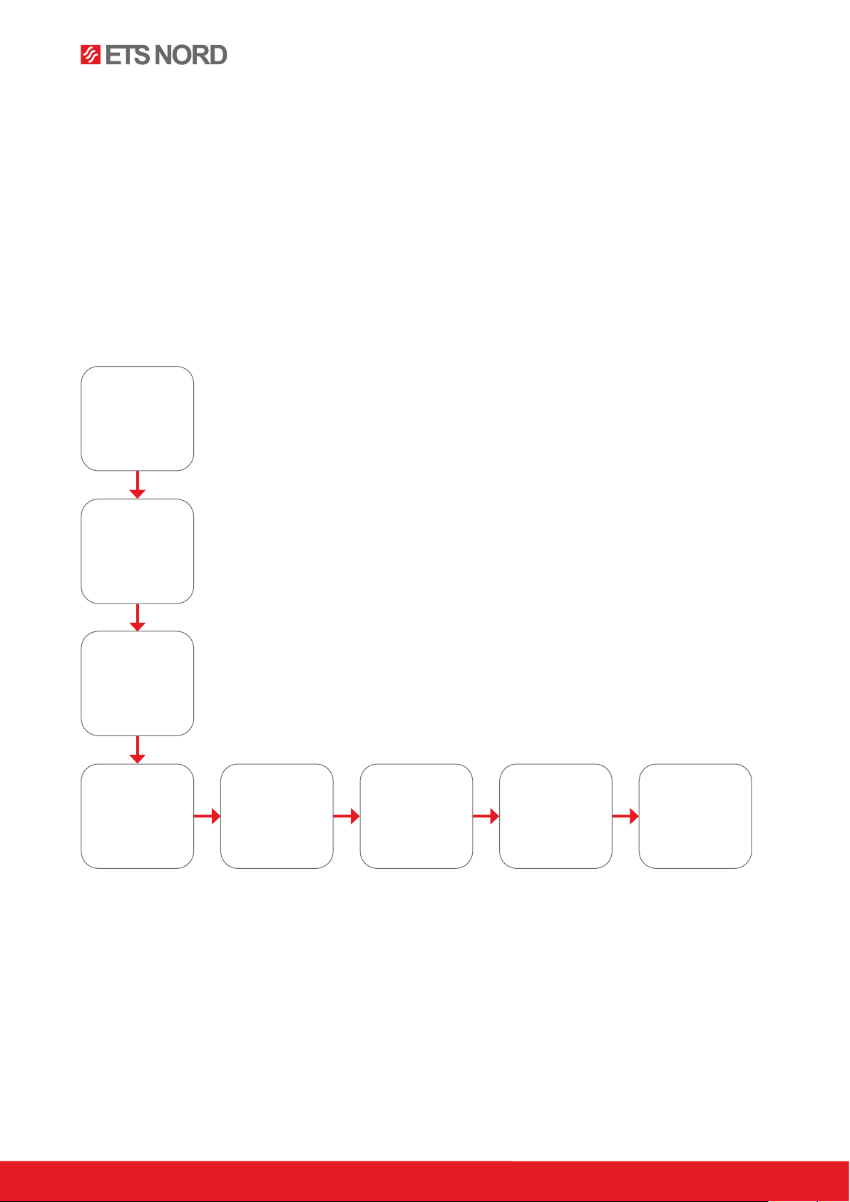
Installation flowchart
For ease of installation and service, it is suggested the installing contractor have the following tools on hand:
• Narrow 2mm flat-head screwdriver
• #1 Phillips screwdriver
• T4 screwdriver
• Small flashlight
• Electrical fish tape
• Silicone and silicone gun
Install ozone
module to
the supply air
chamber
Mount Control
Panel
Perform electrical
installation of the
system
Connect supply
mains for control
panel and ozone
modules
Connect data
wiring for all
ozone modules
Check the product
shipment
Set unique device
addresses and
apply sequential
number stickers
Connect two
pressure
measurement
tubes
www.etsnord.com
4
®
RDM-31-0322
NORDcanopy |OZ 3.1 Installation Guide
1. Check the product shipment
Check that the parcel contains all components listed below and that there is no visible damage.
Notify both the freight forwarder and supplier immediately of any damage or missing components.
Before installing the device read through the entire instruction material.
The Ozone Cleaning System consists of two key components:
- One or more Ozone Modules
- Control Panel
Each OZ 3.1 package contains:
- OZ 3.1 Ozone Module
- Short pressure measurement hose (60cm)
- Long pressure measurement hose (3.5m)
- Power cable with IEC C13 plug (3m)
The Control Panel package contains:
- Control Panel
- One sheet of Ozone Module device address identification labels
There is typically one Control Panel for each kitchen. The number of Ozone Modules is dependent on the design of
the kitchen and the canopy as well as the equipment used for cooking. This is decided when planning the kitchen.
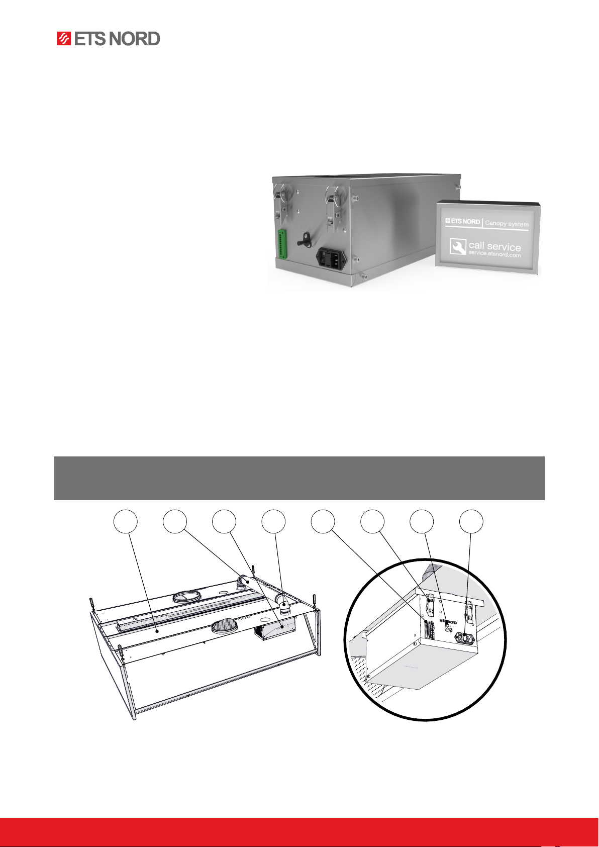
2. System overview
The Ozone Modules produces ozone gas. Ozone (O3) is a very eective oxidant, and when mixed into a kitchen
exhaust airstream it breaks down grease and odor particles to water vapor, carbon dioxide and dry minerals,
all natural products of oxidation which exit the exhaust system.
.
NOTE For best results with odor reduction, the reaction time for ozone within a kitchen exhaust system
should be at least two seconds. However, longer exposure can further improve results. This time
should be taken into account during the design phase of the kitchen exhaust system.
85 762 431
1 – Canopy
2 – Ozone duct Ø100 mm
3 – Ozone Module
4 – Bend Ø100 mm 90° (AISI 316)
5 – Data connector (ModBus, BACnet)
6 – Ozone Module suspension clamps
7 – Ambient air pressure nozzle
8 – Power plug socket for IEC C13 plug

Images are for illustrative purposes.
We reserve the right to make changes. 5
®
RDM-31-0322
NORDcanopy |OZ 3.1 Installation Guide
3. Prepare the Ozone Modules
3.1 Set the device addresses
Each Ozone Module must be set to a unique device address.
Start by removing the bottom cover by unscrewing the four (4)
M5x12 bolts from the side panel with T4 screwdriver and keep
them in a secure place for later use.
To assign unique addresses to Ozone Module a narrow 2mm
flat screwdriver will be needed. All Ozone Modules connected
to a single Control Panel must have a unique device address.
Addresses need to be set in ascending order begin with Ozone
Module closest to the Control Panel and increasing by one for
each sequential module. The first connected Ozone Module
should have the address 1.
Example:
Ozone Module one (Adress 1):
Switch 1x = 1
Switch 10x = 0
Ozone Module thirteen (Adress 13):
Switch 1x = 3
Switch 10x = 1
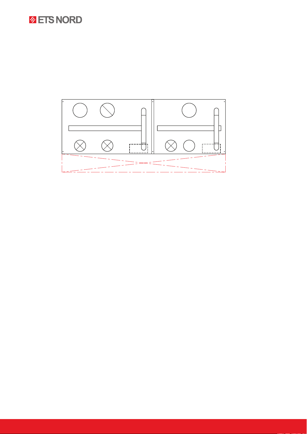
Mark the installation positions of each Ozone Module
The location of each Ozone Module shall be marked by placing
an identification label on the upper front panel of the canopy. The
label should match the device address of the module installed
beneath it. You will find a sheet of labels in the Control Panel
package.
NOTE! Installation may only be carried out byby specialist and authorized persons in accordance with
local, regional, national standards and regulations.
0
0
5
5
1
1
2
2
3
3
4
4
6
6
7
7
8
8
9
9
1x 10x
0
5
1
2
3
4
6
7
8
9
0
5
1
2
3
4
6
7
8
9
Attn! Do not attach the sticker to
the perforated area of the canopy.
www.etsnord.com
6
®
RDM-31-0322
NORDcanopy |OZ 3.1 Installation Guide
4. Installation
4.1 General information
Ozone is drawn into the grease chamber through the ozone duct, which is located on the ceiling of the canopy.
The ducting and bends necessary for connection are included with the canopy.
Always install the ozone ducting according to the manufacturer’s drawings.
The ozone duct must be made of acid-resistant stainless steel (AISI 316).
Before starting the Ozone Module, check visually that all ozone duct connections are airtight.
Always leave a minimum of 500mm free space in front of a canopy to allow access for maintenance.
If the kitchen has already been operational before installation of any Ozone Modules, the exhaust ducts should
be thoroughly cleaned from grease and soot to achieve the best results.
Width of service area
min 500 mm
Never drill or screw into the Ozone Module chassis.

Images are for illustrative purposes.
We reserve the right to make changes. 7
®
RDM-31-0322
NORDcanopy |OZ 3.1 Installation Guide
4.2 Connect the pressure measurement hoses
For an Ozone Module to operate properly its two pressure measurement hoses must be connected.
NOTE! There are two hoses that need to be connected to each module.
- Feed the long hose through the Ø100mm ozone duct into the exhaust chamber.
-
While lifting the module into place, securely attach one end of the hose to the hose located in the
Ozone Module 100mm flange.
- Secure the 4 fixing clamps to fasten the module to the inside roof of the canopy. Clip o the excess
hose as shown in the diagram.
Note the location of the pressure nipple near the module mounting bracket inside the canopy. Securely attach
the shorter hose between the nipples on the module and the canopy.
20cm
2. 3.1.
www.etsnord.com
8
®
RDM-31-0322
NORDcanopy |OZ 3.1 Installation Guide
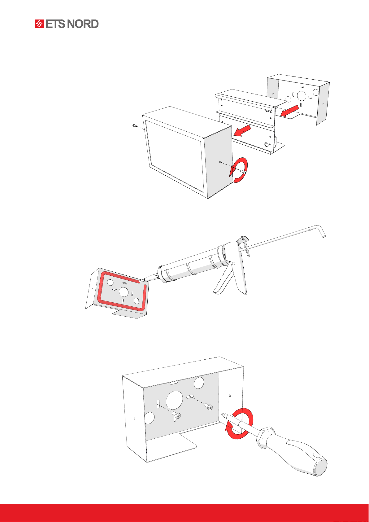
4.3 Mount the Control Panel
Choose a visible and easily accessible location in the kitchen suitable for the Control Panel. Avoid positioning
it near any sources of moisture or heat.
The housing must be disassembled into three parts.
Remove the two fixing screws on the sides of the case.
Before mounting the backplate apply an even strip of waterproof silicone along the rear of the backplate as
pictured below.
Fasten the back plate to the wall with its cable cutout facing downward, preferably at eye level but not higher
than 180 cm from the floor.
Images are for illustrative purposes.
We reserve the right to make changes. 9
®
RDM-31-0322
NORDcanopy |OZ 3.1 Installation Guide
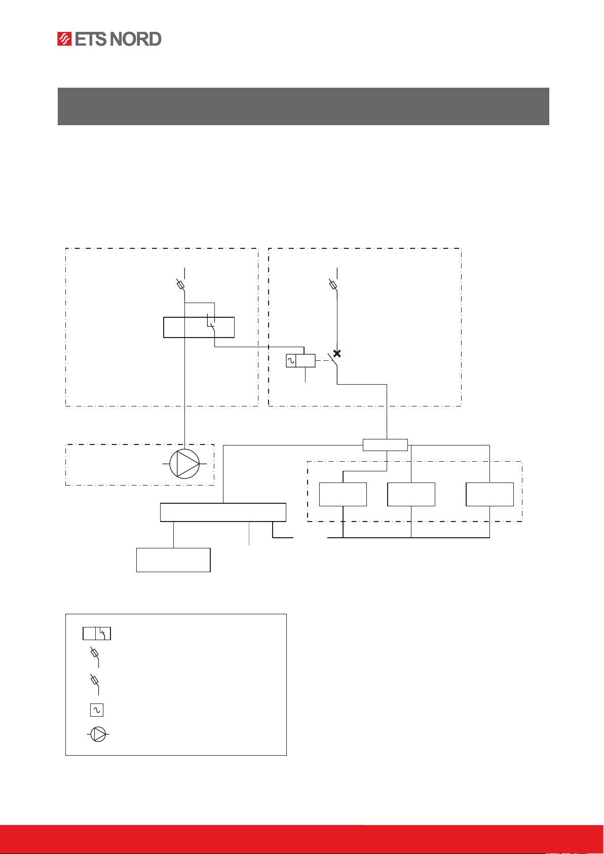
5. Electrical Installation
NOTE! Electrical installation must be performed by an authorized electrician and follow local, regional
and national standards and regulations.
The ozone generator system must be interlocked with the exhaust system, so that when the exhaust ventilation
is not running, no electrical power is supplied to the ozone system. See the sample diagram below as one
possible option to accomplish this function.
A maximum of 4 Ozone Modules and one alarm panel may be connected a single 10A C-type (slow) circuit
breaker. Remember to label the circuit breakers used in the distribution board
.
F1 F2
K1 KL1
<I
L1
N
L1
DISTRIBUTION BOARD NO. 1 DISTRIBUTION BOARD NO. 2
VENTILATION UNIT
CANOPY
F1- Circuit breaker
F2- Ozone Module + Control Panel
Current relay
0...100%
AC relay
Motor, exhaust ventilation fan systems +
motor drive
OZ3 no.1OZ3 no.2
<I
OZ3 no.3
Junction box
Control Panel
<I
I/O
Building automation
PLC
Modbus
BACnet (TCP/IP)
ModBus (TCP/IP)
Ethernet (TCP/IP)

www.etsnord.com
10
®
RDM-31-0322
NORDcanopy |OZ 3.1 Installation Guide
5.1 Connect the main electrical supply
Control Panel power cables may be fed through either the rear wall or the cable bushings in the bottom of the
case. Connect the 230V supply cable to the power supply terminals L, N and PE, as shown in the diagram.
Each Ozone Module has its own power cable that can be found inside the packaging. Connect it to the Ozone
Module as seen in the picture below.
230V supply cable
Power supply
PE
L
N
Supply 230V
IEC C13
Table of contents
Other ETS NORD Cleaning Equipment manuals


