manuals.online logo
Brands
  1. Home
  2. •
  3. Brands
  4. •
  5. EUCHNER
  6. •
  7. Safety Equipment
  8. •
  9. EUCHNER ESM-ES3 Series User manual

EUCHNER ESM-ES3 Series User manual

1
Operating Instructions
Safety Contact Expansion ESM-ES3..
Correct use
The Safety Contact Expansion ESM-ES3.. in combi-
nation with any safety relay from the EUCHNER ESM
series can be used to produce up to three additional
safety paths per device. An existing system can thus
be expanded practically indenitely in a modular
manner. Activation takes place via a safety contact
of the safety relay; the ESM-ES3 provides monitor-
ing contacts for error monitoring. The devices can
be used in systems up to safety category4, PLe
according to EN ISO 13849-1.
Before the device is used, a risk assessment must
be performed on the machine, e.g. according to the
following standards:
fENISO13849-1
fENISO12100
fIEC62061.
Correct use includes observing the relevant require-
ments for installation and operation, particularly
based on the following standards:
fENISO13849-1
fEN60204-1
fIEC62061.
Important!
fThe user is responsible for the integration of
the device in a safe overall system. For this
purpose, the overall system must be validated,
e.g. according to ENISO13849-2.
fThe device user must assess and document
remaining risks.
fIf a data sheet is included with the product, the
information on the data sheet applies.
Safety precautions
WARNING
fInstallation and setup of the device must be
performed only by authorized personnel.
fObserve the country-specic regulations when
installing the device.
fThe electrical connection of the device is only
allowed to be made with the device isolated.
fThe wiring of the device must comply with the
instructions in these operating instructions,
otherwise there is a risk that the safety function
will be lost.
fIt is not allowed to open the device, tamper with
the device or bypass the safety devices.
fAll relevant safety regulations and standards are
to be observed.
fThe overall concept of the control system in
which the device is incorporated must be vali-
dated by the user.
fFailure to observe the safety regulations can re-
sult in death, severe injuries and serious damage.
fNote down the version of the device (see type la-
bel Vx.x.x) and check it each time prior to setup.
If the version changes, the use of the device in
the overall application must be validated again.
Features
f3 safe, redundant relay outputs
1 auxiliary contact (error monitoring)
fActivation via safety relay from the EUCHNER
ESM series
fModular, freely congurable safety system
fError monitoring by safety relay
fGround fault monitoring
fIndication of the switching state via LED
fUse up to PLe, SILCL3, category4
Function
The Safety Contact Expansion ESM-ES3.. in com-
bination with a safety relay from the EUCHNER
ESM series is designed for safe isolation of safety
circuits according to EN 60204-1 and can be
used up to safety category4, PLe according to
EN ISO 13849-1.
Terminal S11 (DC24V control voltage) is connected
with terminals S15 and S16 via the safety contacts
of the safety relay. Starting the safety relay also
activates the ESM-ES3... The safety relay discon-
nects the control voltage when the safety switch is
operated, and the safety contacts of the ESM-ES3..
open immediately.
If a fault occurs in the ESM-ES3.., this is detected by
the safety relay via terminals S23 and S24.
Independent operation without safety relay is
not possible.
Fig. 1: Block diagram for ESM-ES3..
Mounting
As per EN60204-1, the device is intended for in-
stallation in control cabinets with a minimum degree
of protection of IP54. It is mounted on a 35 mm
mounting rail according to DINEN60715TH35.
Fig. 2: Mounting/removing
Electrical connection
fWhen the 24 V version is used, a safety transform-
er according to EN61558-2-6 or a power supply
unit with electrical isolation from the mains must
be connected.
fExternal fusing of the safety contacts must be
provided.
fA maximum length of the control lines of 1,000 m
with a conductor cross-section of 0.75mm² must
not be exceeded.
fThe conductor cross-section must not exceed
2.5mm².
fIf the device does not function after setup, it must
be returned to the manufacturer unopened. Open-
ing the device will void the warranty.
fPE (protective earth) must be connected to termi-
nal S10 on the AC115/230V variant. Wiring of
the overall device is to be designed for 115/230V.
A1 Power supply
A2 Power supply
S11 DC24V control voltage
S10 Control line
S15 Control line
S16 Control line
S23 Error monitoring
S24 Error monitoring
13-14 Safety contact 1
23-24 Safety contact 2
33-34 Safety contact 3
Fig. 3: Connections
Setup procedure
Notice
The items listed under Electrical connection must
be observed during setup.
1. Wiring ESM-ES3..:
Wire the ESM-ES3.. with the EUCHNER safety relay
according to your application (see Fig. 5 and Fig. 6).
2. Wiring safety relay:
Wire the safety relay according to the required
Performance Level determined (see operating
instructions for the safety relay).
3. Wiring feedback loop:
Wire the feedback loop as shown in Fig. 7 and Fig. 8.
4. Wiring power supply:
Connect the power supply to terminals A1 and A2
(see Fig. 9).
Attention: Wiring only in de-energized state.
5. Starting the device:
Switch the operating voltage on.
Attention: If the Automatic start behavior is set
on the safety relay, the safety contacts will close
immediately.
If the Monitored manual start behavior is set, close
the start button to close the safety contacts.
The LEDs K1 and K2 on the safety relay and on the
ESM-ES3.. illuminate.
6. Activating safety function:
Open the emergency stop circuit by actuating the
connected safety switch. The safety contacts of the
safety relay and the ESM-ES3.. open immediately.
7. Reactivating:
Close the emergency stop circuit. If Automatic start
is selected on the safety relay, the safety contacts
will close immediately.
If the Monitored manual start behavior is set, close
the start button on the safety relay to close the safe-
ty contacts of the safety relay and the ESM-ES3...

2
Operating Instructions
Safety Contact Expansion ESM-ES3..
What to do in case of a fault?
Device does not switch on:
fCheck the wiring of the ESM-ES3.. and the safety
relay by comparing it with the wiring diagrams (also
see operating instructions for the safety relay).
fCheck the safety switch used on the safety relay
for correct function and adjustment.
fCheck whether the emergency stop circuit of the
safety relay is closed.
fCheck whether the start button on the safety relay
(with manual start) is closed.
fCheck the operating voltage at A1 and A2 on the
safety relay and on the ESM-ES3...
fIs the feedback loop closed?
Device cannot be switched on again after an
emergency stop:
fCheck whether the emergency stop circuit was
closed again.
fWas the start button opened before closing of the
emergency stop circuit (with manual start)?
fIs the feedback loop closed?
fIs the power supply present during the time
sequence?
If the fault persists, perform the steps listed under
Setup procedure.
If these steps do not remedy the fault either, return
the device to the manufacturer for examination.
Opening the device is impermissible and will
void the warranty.
Maintenance
The device must be checked once per month for
proper function and for signs of tampering and
bypassing of the safety function. The device is
otherwise maintenance-free, provided that it was
installed properly.
Disposal
Pay attention to the applicable national regulations
and laws during disposal.
EU declaration of conformity
The declaration of conformity is part of the operating
instructions, and it is included as a separate sheet
with the device.
The EU declaration of conformity can also be found
at: www.euchner.com
Service
If servicing is required, please contact:
EUCHNER GmbH + Co. KG
Kohlhammerstraße 16
70771 Leinfelden-Echterdingen
Germany
Service telephone:
+49 711 7597-500
E-mail:
support@euchner.de
Internet:
www.euchner.com
Technical data
Parameter Value
Version ESM-ES301 ESM-ES302 ESM-ES303
Operating voltage AC/DC 24 V AC 115V AC 230 V
Rated supply frequency 50 - 60 Hz
Permissible deviation ± 10%
Power consumption DC 24 V AC 230 V
Approx. 1.2 W Approx. 3.5 VA
Control voltage at S11 DC 24 V
Control current S11…S14 Approx. 40 mA
Safety contacts 3 NO contacts
Monitoring contacts 1 NC contact (monitoring contact for safety relay)
Max. switching voltage AC 250 V
Safety contact breaking capacity
(13-14, 23-24, 33-34)
AC: 250 V, 1.500 VA, 6 A for ohm resistive load
250 V, 4 A for AC-15
DC: 24 V, 30 W, 1.25 A for ohm resistive load
24 V, 2 A, for DC-13
Max. cumulative current of all safety
contacts 10.5 A
Minimum contact load 24 V, 20 mA
Contact fuses 6 A gG
Conductor cross-section 0.14 - 2.5 mm²
Max. length of control cable 1,000 m with 0.75 mm²
Contact material AgNi
Mech. contact life Approx. 1 x 10⁷
Test voltage 2.5 kV (control voltage/contacts)
Rated impulse withstand voltage, leakage
paths/air gaps 4 kV (DIN VDE 0110-1)
Rated insulation voltage 250 V
Degree of protection IP20
Temperature range DC24V: -15°C to +60°C
AC230V/115V/24V: -15°C to +40°C
Degree of contamination 2 (DIN VDE 0110-1)
Overvoltage category 3 (DIN VDE 0110-1)
Weight Approx. 230g
Mounting Mounting rail according to DIN EN 60715 TH35
Reliability values according to EN ISO 13849-1 for all variants of the series ESM-ES3 1)
Load (DC-13; 24V) ≤0.1 A ≤1 A ≤2A
nop ≤400,000 cycles ≤73,000 cycles ≤17,000 cycles
T10D 20 years
Category 4
PL e
PFHD1.2x10-8 1/h
1) Additional data can be requested from the manufacturer for applications that deviate from these conditions.
Fixed terminals Plug-in terminals
Fig. 4: Dimension drawing for ESM-ES3..
Operating Instructions
Safety Contact Expansion ESM-ES3..
3
Subject to technical modications; no responsibility is accepted for the accuracy of this information. © EUCHNER GmbH + Co. KG 2090074-10-08/22 V1.1.0 (translation of the original operating instructions)
Applications
Depending on the application, the device must be wired with a EUCHNER safety relay as shown in Fig. 5 and Fig. 6.
If the devices are wired inside a control cabinet (minimum degree of protection IP54), the fault involving a short circuit between the activation lines can be
ruled out (protected wiring space). Category 4, PL e according to EN ISO 13849-1 is thereby possible.
If this fault cannot be ruled out, category3, PLe is achieved.
Wiring
Fig. 5: Connection of ESM-ES3.. to safety relay
Wiring of the ESM-ES3.. via only 4 lines:
A safety contact of the safety relay (e.g. 13-14) activates the relays of the
ESM-ES3.. (S11 and S15 / S16).
Two lines on S23 and S24 are required for feedback/error monitoring. This is
to be wired, depending on the application, as per Fig. 7 or Fig. 8.
An error in the ESM-ES3.. thereby prevents the entire safety chain from restart-
ing. Earth faults in the control lines are detected in addition to internal faults.
Fig. 6: Connection of several ESM-ES3.. units to safety relay
If further ESM-ES3.. units are to be integrated into the system, terminals
S11 must be connected in parallel on all ESM-ES3.. units. This also applies
to terminals S10 and terminals S15 / S16.
The feedback loops (S23-S24) for the individual expansion devices must be
connected in series with the start for the safety relay (cf. Fig. 7 or Fig. 8).
Notice:
In order to activate ground fault monitoring, S10 must be connected to PE (protective earth) on the AC115/230V devices. With AC/DC24V, connect PE
only to the power supply unit according to EN60204-1.
Feedback loop
Fig. 7: Feedback loop.
Contactors connected to the ESM-ES3.. or the safety relay are monitored
via the feedback loop of the safety relay. KA and KB are the positively driven
contacts of the connected contactor or expansion module.
Fig. 8: Feedback loop with automatic start.
Contactors connected to the ESM-ES3.. or the safety relay are monitored
via the feedback loop of the safety relay. KA and KB are the positively driven
contacts of the connected contactor or expansion module.
Power supply and safety contacts
Fig. 9: Connection of the power supply to terminals A1 and A2 (power supply
according to the technical data).
Fig. 10: Connection to switching loads on safety contacts
(example contact conguration. Differing according to
device type. Switching voltages +V corresponding to
technical data).

This manual suits for next models

3

Other EUCHNER Safety Equipment manuals

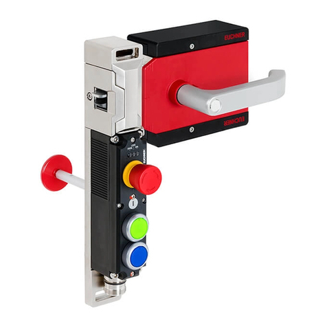
EUCHNER MGB2-L1 User manual

EUCHNER

EUCHNER MGB2-L1 User manual

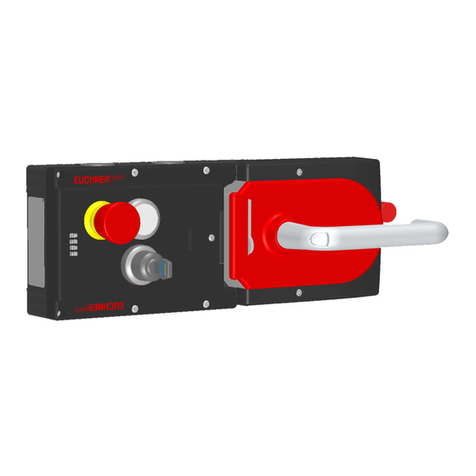
EUCHNER MGB2-L series User manual

EUCHNER

EUCHNER MGB2-L series User manual

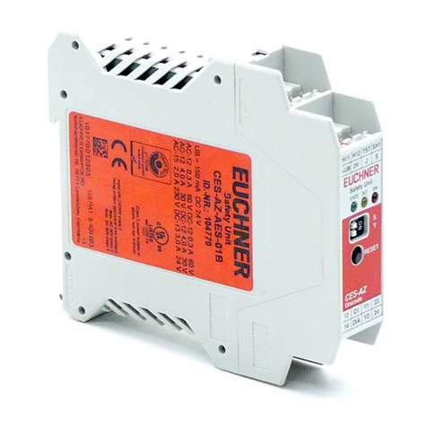
EUCHNER CES-AZ-UES Series User manual

EUCHNER

EUCHNER CES-AZ-UES Series User manual

EUCHNER 156622 User manual

EUCHNER

EUCHNER 156622 User manual

EUCHNER MGBS-P-L AP Series User manual

EUCHNER

EUCHNER MGBS-P-L AP Series User manual

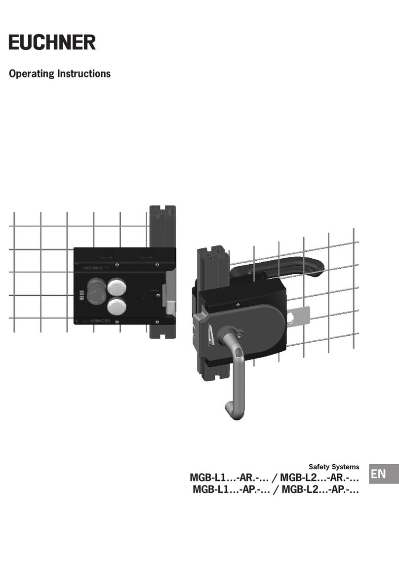
EUCHNER MGB-L1 AR Series User manual

EUCHNER

EUCHNER MGB-L1 AR Series User manual

EUCHNER CTS-C1-BP-FLX User manual

EUCHNER

EUCHNER CTS-C1-BP-FLX User manual

EUCHNER SGP-TW Series User manual

EUCHNER

EUCHNER SGP-TW Series User manual

EUCHNER CTP User manual

EUCHNER

EUCHNER CTP User manual

EUCHNER NX Series User manual

EUCHNER

EUCHNER NX Series User manual

EUCHNER MGB-L0 AR Seris User manual

EUCHNER

EUCHNER MGB-L0 AR Seris User manual

EUCHNER CES-AZ-AES Series User manual

EUCHNER

EUCHNER CES-AZ-AES Series User manual

EUCHNER MGB2-I-BP Series User manual

EUCHNER

EUCHNER MGB2-I-BP Series User manual

EUCHNER NZ VZ AS Series User manual

EUCHNER

EUCHNER NZ VZ AS Series User manual

EUCHNER ESH Series User manual

EUCHNER

EUCHNER ESH Series User manual

EUCHNER CES-AZ-UBS-01B User manual

EUCHNER

EUCHNER CES-AZ-UBS-01B User manual

EUCHNER MGBS-P-I-AP Series User manual

EUCHNER

EUCHNER MGBS-P-I-AP Series User manual

EUCHNER CES-AZ-AES Series User manual

EUCHNER

EUCHNER CES-AZ-AES Series User manual

EUCHNER MGBS-P-L2-AP-U-R-AZ-SA-163900 User manual

EUCHNER

EUCHNER MGBS-P-L2-AP-U-R-AZ-SA-163900 User manual

EUCHNER LCA-4-T User manual

EUCHNER

EUCHNER LCA-4-T User manual

EUCHNER LCA 2 Series User manual

EUCHNER

EUCHNER LCA 2 Series User manual

EUCHNER MGBS-P-L AR Series User manual

EUCHNER

EUCHNER MGBS-P-L AR Series User manual

EUCHNER MGB-L1-APA-AP4A1-S1-R-158117 User manual

EUCHNER

EUCHNER MGB-L1-APA-AP4A1-S1-R-158117 User manual

EUCHNER MGB-L B-PN Series User manual

EUCHNER

EUCHNER MGB-L B-PN Series User manual

Popular Safety Equipment manuals by other brands

Inshore 380N Servicing manual

Inshore

Inshore 380N Servicing manual

SKYLOTEC SKN Series Instructions for use

SKYLOTEC

SKYLOTEC SKN Series Instructions for use

Mustang Survival MD2020 owner's manual

Mustang Survival

Mustang Survival MD2020 owner's manual

Scott SCOTT TRAIL PROTECT FR'10 user manual

Scott

Scott SCOTT TRAIL PROTECT FR'10 user manual

Seago ELITE instructions

Seago

Seago ELITE instructions

EDELRID SMART BELAY X manual

EDELRID

EDELRID SMART BELAY X manual

E2S E2xC1X05R manual

E2S

E2S E2xC1X05R manual

Honeywell Miller EN 795 manual

Honeywell

Honeywell Miller EN 795 manual

Lanex PB-20 instruction manual

Lanex

Lanex PB-20 instruction manual

SKYLOTEC ANCHOR ROPES Instructions for use

SKYLOTEC

SKYLOTEC ANCHOR ROPES Instructions for use

TEUFELBERGER NODUS Manufacturer's information and instructions for use

TEUFELBERGER

TEUFELBERGER NODUS Manufacturer's information and instructions for use

Salewa MTN SPIKE user manual

Salewa

Salewa MTN SPIKE user manual

Sitec TX MATIC operating manual

Sitec

Sitec TX MATIC operating manual

TEUFELBERGER GRIP 12 Manufacturer's information and instructions for use

TEUFELBERGER

TEUFELBERGER GRIP 12 Manufacturer's information and instructions for use

Micro Detectors AE Series installation manual

Micro Detectors

Micro Detectors AE Series installation manual

Kortel Design KONCEPT user manual

Kortel Design

Kortel Design KONCEPT user manual

Carl Stahl Kromer 7200 operating instructions

Carl Stahl Kromer

Carl Stahl Kromer 7200 operating instructions

MSA G1 SCBA operating manual

MSA

MSA G1 SCBA operating manual

manuals.online logo
manuals.online logoBrands
  • About & Mission
  • Contact us
  • Privacy Policy
  • Terms and Conditions

Copyright 2025 Manuals.Online. All Rights Reserved.