Harken Access Rail R27 LS User manual

R27 LS ACCESS RAIL ON METAL ROOFS
Installation manual
Range of INBRKT.XNbrackets
Read the manual carefully before using the system.
Translation of the
Original Instructions
UINBRKT.XN-A 16-01-20


16/01/2020 ENGLISH 3
Safety information..............................................................................................................Page 4
Components .....................................................................................................................Page 5
INBRKT.X4(STIFFENING BRACKET) ........................................................................................................ P
age
5
INBRKT.X5(END BRACKET)..................................................................................................................... P
age
6
INBRKT.X6(MIDDLE BRACKET) .............................................................................................................. P
age
7
Features..........................................................................................................................Page 8
FEATURES OF THE ANCHORING DEVICES AND BRACKET ASSEMBLY................................................... Page 8
ANCHORING DEVICE FOR RAIL R27 LS + INBRKT.XN............................................................................ Page 9
STANDARD INSTALLATION LAYOUT R27 LS + INBRKT.XN................................................................... Page 10
Component descriptions
..................................................................................................... Page 13
STIFFENING BRACKET (CODE INBRKT.X4
)............................................................................................ Page 13
ASSEMBLY (CODE INBRKT.X4
).............................................................................................................. Page 14
END BRACKET (CODE INBRKT.X5
)........................................................................................................ Page 15
ASSEMBLY (CODE INBRKT.X5
).............................................................................................................. Page 16
MIDDLE BRACKET (CODE INBRKT.X6
).................................................................................................. Page 17
ASSEMBLY (CODE INBRKT.X6
).............................................................................................................. Page 18
Installation methods ......................................................................................................... Page 19
INSTALLATION ON CORRUGATED ROOFS OR SANDWICH PANELS .....................................................
Page 19
INSTALLING THE SEALS........................................................................................................................
Page 19
ANCHORING DEVICE..............................................................................................................................
Page 19
END BRACKETS (CODE INBRKT.X5)......................................................................................................
Page 20
MIDDLE BRACKETS (CODE INBRKT.X6)................................................................................................
Page 21
Feet on request ............................................................................................................... Page 22
FEET ON REQUEST.................................................................................................................................
Page 22
Contacts ........................................................................................................................
Page 23
Table of Contents

4 ENGLISH 16/01/2020
SAFETY INFORMATION
SAFETY INFORMATION
WARNING!
Before installing the product, carefully read the R27 LS access rail instruction manual.

16/01/2020 ENGLISH 5
COMPONENTS
COMPONENTS
INBRKT.X4(STIFFENING BRACKET)
- Stiffening bracket (upper diagonal rib, lower diagonal rib)
- Fixing feet
- Fixing bolts
- Rivets
- Seals
- INFIX1.LS insert
- M10x25 screw
- Washer

6 ENGLISH 16/01/2020
COMPONENTS
INBRKT.X5(END BRACKET)
- End bracket (upper diagonal rib, lower diagonal rib, tie-rod plate)
- Fixing feet
- Fixing bolts
- Rivets
- Seals
- INFIX1.LS insert
- M10x25 screw
- Washer

16/01/2020 ENGLISH 7
COMPONENTS
INBRKT.X6(MIDDLE BRACKET)
- Middle bracket (upper diagonal rib, lower diagonal rib, double tie-rod plate)
- Fixing feet
- Fixing bolts
- Rivets
- Seals
- INFIX1.LS insert
- M10x30 screw
- Washer

8 ENGLISH 16/01/2020
FEATURES OF THE ANCHORING DEVICES AND BRACKET ASSEMBLY
The materials and minimum thicknesses required according to the type of roof on which the anchoring
devices in the INBRKT.XNrange are installed are given below. The following table refers to the roof profile, on
which fixings must be done exclusively using the rivets supplied by HARKEN.
FEATURES
STEEL SANDWICH PANELS MINIMUM THICKNESS 0.4 mm
ALUMINIUM SANDWICH PANELS MINIMUM THICKNESS 0.6 mm
STEEL SHEET MINIMUM THICKNESS 0.6 mm
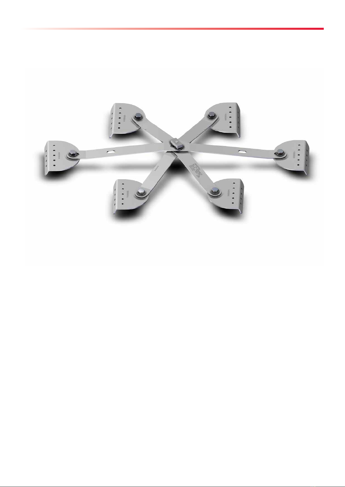
The INBRKT.XNbrackets are supplied with rivets and standard fixing feet and relative fixing bolts.
Using:
• standard fixing feet,
• the fixing bolts between these and the other components of the device,
• the rivets supplied by HARKEN,
on corrugated sheet and sandwich panels of suitable thicknesses, for which fixing between the anchoring
device and the corrugated sheet and sandwich panel is suitable.
Check the seal between the sandwich panel or corrugated sheet and the underlying structure, as well as the
ability of the latter to resist the forces transmitted by the anchoring system.
The system has been tested in compliance to:
- UNI 11578:2015 type D for use by 4 operators at the same time
- EN 795:2012 type D
- CEN/TS 16415:2013 type D for use by 4 operators at the same time.
For some corrugated sheet the standard fixing feet shape may not be suitable. In these cases it is possible to
design and use non-standard support bases/fixing feet: these must be sized by the designer qualified for
structural calculations as they are a part of the anchoring device fixing system. The project also includes the
calculation of the fixing sizes: the type of rivet/screw, their number and arrangement (in this case there is no
obligation to use rivets supplied by HARKEN as the sizing is done by an external designer).
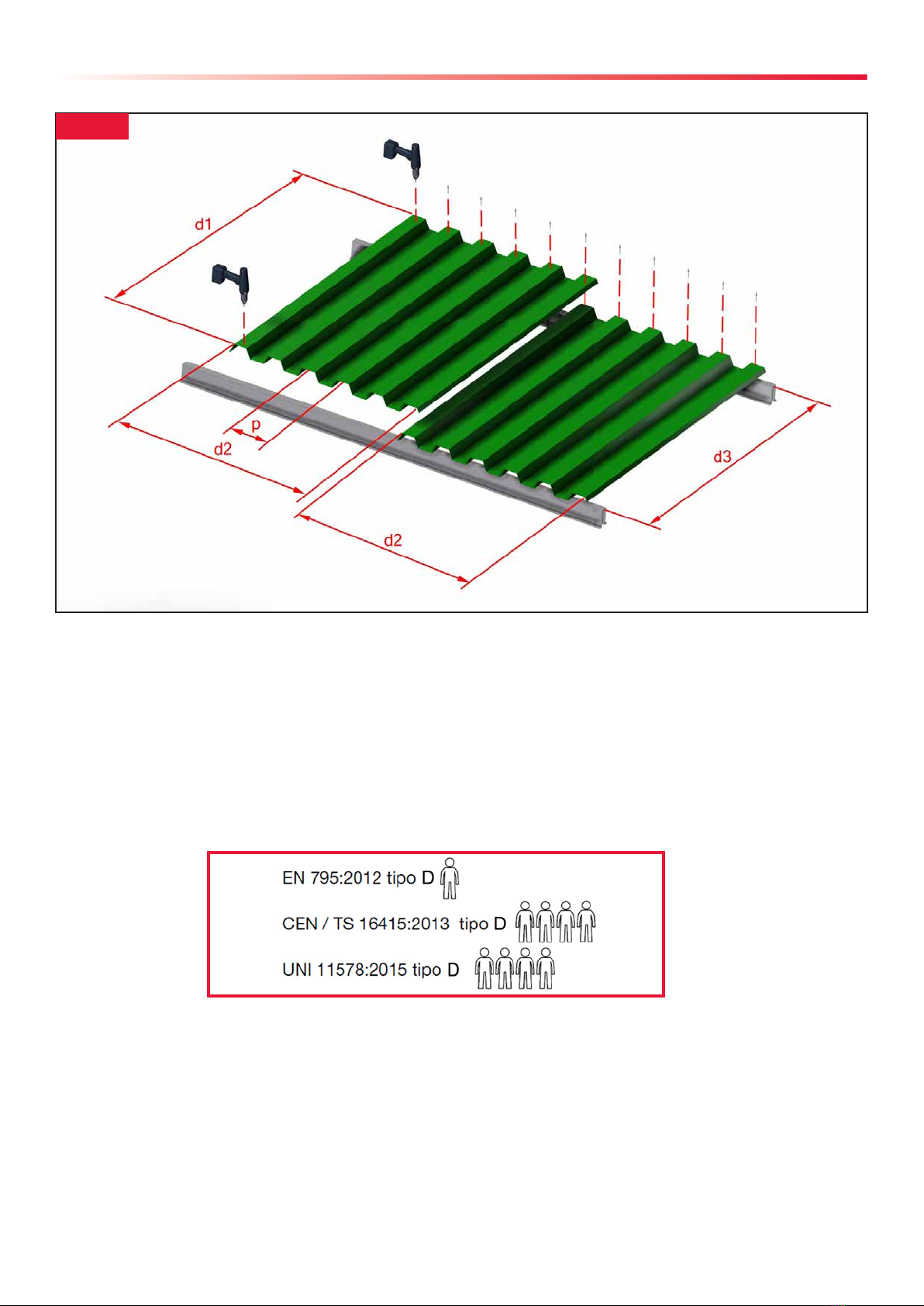
The situation described below refers to the field tests for connection between sandwich panel/corrugated
sheet and the underlying structure.
As shown in the following figure (Fig.1) the tests were carried out on 2 portions of roof, each measuring d1=
2 m and d2=1 m, coupled together to form a surface area of 2 m x 2 m. The distance between the fixing rows
was, for the purpose of safety, the maximum permitted by the corrugated roofing manufacturer, i.e. d3=1.5
m. The fixing used met the requirements of the corrugated roof manufacturer’s technical data sheet, for
fixings on iron omega profiles, as this was the type of underlying structure: the fixing was chosen according
to the underlying structure (wood, steel, reinforced concrete, etc., and their characteristics). A fixing was
installed on every corrugated angle, both in the upper and lower fixing row in relation to the device
positioning: during the test, the omega profiles were found to be solidly fixed to the test field structure. The
device fixed on the corrugated roof using the rivets supplied did not overlap or cross a fixing row.

16/01/2020 ENGLISH 9
ANCHORING DEVICE TO RAIL R27 LS + INBRKT.XN
The fall protection system consisting of the rail R27.LS + brackets for sandwich panel or corrugated sheet is:
- Certified UNI 11578:2015 type D for use by 4 operators at the same time
- Conforming to EN 795:2012 type D
- Conforming to CEN/TS 16415:2013 type D for use by 4 operators at the same time.
Figure 1
The maximum number of users at the same time can be decreased by the designer or inspector/maintenance
operator for motivated reasons which many not have been envisaged during the design and manufacture of
the device, for example linked to the place of installation or the resistance of the fixing and the support.
Single- and multi-span device used to obtain lines of indefinite length. The maximum span is 3 m. For lines
consisting of 2 or more rails, install intermediate supports, which will form spans of maximum 3 m length
(measures taken from the plate centre to the adjacent plate centre, see Fig.2).
FEATURES

10 ENGLISH 16/01/2020
STANDARD INSTALLATION LAYOUT R27 LS + INBRKT.XN
Suitable for installation on horizontal or angled surfaces, wall or ceiling installation is not permitted. As for
the installation surfaces, the user may work on both horizontal and angled roofs/work places. The linear
anchoring device is used in a perpendicular direction to the rail, in the direction of the slope on the roof
(Fig.3).
Figure 2
Figure 3
Some examples of permitted configurations are given below (Fig.4a and 4b) along with others which must
not be used (Fig.4c).
Figure 4a Figure 4b Figure 4c
FEATURES
FALL PROTECTION SYSTEM

16/01/2020 ENGLISH 11
The anchoring line to connect to is the rail R27 LS (Fig.5), from which it is possible to work when using
suitable PFPE (Personal Fall Protection Equipment) to protect from falling in restraint, work positioning and
fall arrest. It is possible to connect to the rail directly using one or more trolleys in the Access Rail System
series (see R27 Long Span Instruction Manual).
The maximum number of operators working on the rail at the same time, each with their own trolley, is 4 per
span. These operators must have maximum weight 100 kg each.
To use the system for human suspension system, the line must be stiffened using the stiffening brackets
INBRKT.X4, to create spans of MAX 1.5 m (Fig.6).
Figure 5
Figure 6
FEATURES
HUMAN SUSPENSION SYSTEM

12 ENGLISH 16/01/2020
FALL PROTECTION SYSTEM
Lmax = 3000 mm
HUMAN SUSPENSION SYSTEM
Lmax = 1500 mm
FEATURES

16/01/2020 ENGLISH 13
COMPONENT DESCRIPTIONS
STIFFENING BRACKET (CODE INBRKT.X4
)
Suitable for 25 to 50 cm crown spans (sheet profile), the components must be assembled (as explained in
detail in the next paragraph). The stiffening bracket can be integrated into a line to create a more rigid
system.
Every INBRKT.X4bracket consists of:
• UPPER diagonal rib (Fig.7).
• LOWER diagonal rib (Fig.8).
The upper diagonal rib (Fig. 7) and the
lower diagonal (Fig. 8) differ by their
bending angle: to recognise them and
not invert them during assembly, the
complete device markings are given on
the upper diagonal rib, while only the
batch number on the lower diagonal rib.
• FIXING FEET (standard) (Fig.9)
Interface for fixing on corrugated roofs
with permitted shapes and thicknesses,
using the rivets supplied, directly to the
profile crown of the sandwich panel or
corrugated sheet. The feet are already bent
at an internal angle of 120°, but they can
be ordered with different angles (the
internal angle that HARKEN can supply
remaining within the idea of standard
fixing feet is in the range of 90° / 150°): do
not tamper with or modify the finished
element supplied by HARKEN. 4 fixing feet
are required for each stiffening bracket.
• Rail/Bracket FIXING KIT (Fig.10)
1 threaded insert INFIX1.LS.
1 screw M10x25 in A2/70.
1 washer for connection between the
diagonal ribs.
Figure 7Figure 8
Figure 9
Figure 10

14 ENGLISH 16/01/2020
• 4 SEALS (Fig.11)
one for each foot, thickness 0.75 mm, adhesive type,
for complete waterproof protection with excellent
springback, also required to prevent direct contact
between the support profile and the fixing feet intrados.
• FOOT ASSEMBLY BOLTS (Fig.12)
Fixing bolts for assembling the fixing feet: required for
component assembly. Do not use bolts or components
other than those supplied by HARKEN.
4 bolts M12x25 in A2/70, with double washer and self-
locking nut for connection between the ends of the
diagonal ribs and the fixing feet on corrugated roofs.
The figure shows the components of a complete bolt.
• RIVETS
For fixing between the feet and the corrugated roof
support, 9 rivets are needed for each fixing foot. 10 are
supplied for each foot, for a total of 40 rivets per
bracket. Do not use rivets other than those supplied by
HARKEN.
The references to the rivet models supplied are given
here.
Figure 11
Figure 12
ASSEMBLY SYSTEM (CODE INBRKT.X4
)
The figure below (Fig.13) describes the assembly system.
During initial assembly do not fully tighten the bolted joints, allowing the device to remain mobile when fitting
the feet on the roof corrugations.
Figure 13
COMPONENT DESCRIPTIONS

16/01/2020 ENGLISH 15
END BRACKET (CODE INBRKT.X5
)
Suitable for 25 to 50 cm crown spans (sheet profile), the components must be assembled (as explained in
detail in the next paragraph). Each line requires 2 end brackets.
Every INBRKT.X5bracket consists of:
• UPPER diagonal rib (Fig.14).
• LOWER diagonal rib (Fig.15).
The upper diagonal rib (Fig.14) and the
lower diagonal (Fig. 15) differ by their
bending angle: to recognise them and not
invert them during assembly, the complete
device markings are given on the upper
diagonal rib, while only the batch number
on the lower diagonal rib. Figure 14 Figure 15
• TIE-ROD PLATE (Fig.16)
The length and holes of the tie-rod plate depend on the
corrugated sheet pitch, so before ordering specify the pitch
and before installation check that the element is long
enough. The standard tie-rod plate, with 2 holes, is suitable
for pitches of 25 cm and 33 cm. For different pitches in the
permitted range (25/50 cm), the plate is supplied to
measure.
• FIXING FEET (standard) (Fig.17)
Interface for fixing on corrugated roofs with permitted
shapes and thicknesses, using the rivets supplied, directly to
the profile crown of the sandwich panel or corrugated sheet.
The feet are already bent at an internal angle of 120°, but
they can be ordered with different angles (the internal angle
that HARKEN can supply remaining within the idea of
standard fixing feet is in the range of 90° / 150°): do not
tamper with or modify the finished element supplied by
HARKEN. 5 fixing feet are required for each end bracket.
Figure 16
Figure 17
COMPONENT DESCRIPTIONS

16 ENGLISH 16/01/2020
Figure 18
• Rail/Bracket FIXING KIT (Fig.18)
1 threaded insert INFIX1.LS.
1 bolt M10x25 in A2/70.
1 washer for connection between the diagonal ribs.
• 4 SEALS (Fig.19)
5, one for each foot, thickness 0.75 mm, adhesive
type, for complete waterproof protection with excellent
springback, also required to prevent direct contact
between the support profile and the fixing feet intrados.
• FOOT ASSEMBLY BOLTS (Fig.20)
Fixing bolts for assembling the fixing feet: required for
component assembly. Do not use bolts or components
other than those supplied by HARKEN.
5 bolts M12x25 in A2/70, with double washer and
self-locking nut for connection between the ends of
the diagonal ribs or tie-rod plate and the fixing feet on
corrugated roofs. The figure shows the components
of a complete bolt.
• RIVETS
For fixing between the feet and the corrugated roof
support, 9 rivets are needed for each fixing foot. 10
are supplied for each foot, for a total of 50 rivets per
bracket. Do not use rivets other than those supplied by
HARKEN.
The references to the rivet models supplied are given
here.
Figure 19
Figure 20
ASSEMBLY SYSTEM (CODE INBRKT.X5
)
The figure below (Fig. 21) describes the assembly system: specifically the tie-rod plate is assembled for
installations with pitch 25 cm. If the pitch is 33 cm simply assemble the tie-rod plate to the 2 diagonal ribs
through the hole closest to the fixing foot. Equally, if the tie-rod plate is not standard, assemble with the
specifically made hole. During initial assembly do not fully tighten the bolted joints, allowing the device to
remain mobile when fitting the feet on the roof corrugations.
Figure 21
COMPONENT DESCRIPTIONS

16/01/2020 ENGLISH 17
MIDDLE BRACKET (CODE INBRKT.X6
)
Suitable for 25 to 50 cm crown spans (sheet profile), the components must be assembled (as explained in
detail in the next paragraph). Every line made with more than one rail must consist of middle brackets
between the 2 end brackets, with maximum spacing of 3 m.
Every INBRKT.X6bracket consists of:
• UPPER diagonal rib (Fig.22).
• LOWER diagonal rib (Fig.23).
The upper diagonal rib (Fig.22) and the
lower diagonal (Fig. 23) differ by their
bending angle: to recognise them and not
invert them during assembly, the complete
device markings are given on the upper
diagonal rib, while only the batch number
on the lower diagonal rib. Figure 22 Figure 23
• 2 TIE-ROD PLATES (Fig.24)
The length and holes of the tie-rod plate depend on the
corrugated sheet pitch, so before ordering specify the pitch
and before installation check that the element is long
enough. The standard tie-rod plate, with 2 holes, is suitable
for pitches of 25 cm and 33 cm. For different pitches in the
permitted range (25/50 cm), the plate is supplied to
measure.
• FIXING FEET (standard) (Fig.25)
Interface for fixing on corrugated roofs with permitted
shapes and thicknesses, using the rivets supplied, directly to
the profile crown of the sandwich panel or corrugated sheet.
The feet are already bent at an internal angle of 120°, but
they can be ordered with different angles (the internal angle
that HARKEN can supply remaining within the idea of
standard fixing feet is in the range of 90° / 150°): do not
tamper with or modify the finished element supplied by
HARKEN. 6 fixing feet are required for each middle bracket.
Figure 24
Figure 25
COMPONENT DESCRIPTIONS

18 ENGLISH 16/01/2020
Figure 26
• Rail/Bracket FIXING KIT (Fig.26)
1 threaded insert INFIX1.LS.
1 screw M10x30 in A2/70.
1 washer for connection between the diagonal ribs.
• 4 SEALS (Fig.27)
6, one for each foot, thickness 0.75 mm, adhesive
type, for complete waterproof protection with excellent
springback, also required to prevent direct contact
between the support profile crown and the fixing feet
intrados.
• FOOT ASSEMBLY BOLTS (Fig.28)
Fixing bolts for assembling the fixing feet: required for
component assembly. Do not use bolts or components
other than those supplied by HARKEN.
6 bolts M12x25 in A2/70, with double washer and
self-locking nut for connection between the ends of
the diagonal ribs or tie-rod plate and the fixing feet on
corrugated roofs. The figure shows the components
of a complete bolt.
• RIVETS
For fixing between the feet and the corrugated roof
support, 9 rivets are needed for each fixing foot. 10
are supplied for each foot, for a total of 60 rivets per
bracket. Do not use rivets other than those supplied by
HARKEN.
The references to the rivet models supplied are given
here.
Figure 27
Figure 28
ASSEMBLY SYSTEM (CODE INBRKT.X6
)
The figure below (Fig.29) describes the assembly system: specifically the two tie-rod plates are assembled for
installations with pitch 25 cm. If the pitch is 33 cm simply assemble the two tie-rod plates to the 2 diagonal ribs
through the hole closest to the fixing foot. Equally, if the two tie-rod plates are not standard, assemble with the
specifically made hole. During initial assembly do not fully tighten the bolted joints, allowing the device to
remain mobile when fitting the feet on the roof corrugations.
Figure 29
COMPONENT DESCRIPTIONS

16/01/2020 ENGLISH 19
INSTALLATION METHODS
INSTALLATION ON CORRUGATED ROOFS OR SANDWICH PANELS
Before fixing the anchoring devices to the sandwich panels or corrugated sheet, check that these supports
comply with the minimum conditions set out in the table in the previous chapter.
INSTALLING THE SEALS
Remember that before proceeding with the installation of each device or element, apply the anti-infiltration
seal supplied for each foot. The following diagram shows the procedure to be followed for installation
(Fig.30):
ANCHORING DEVICE
Having pre-assembled the end and middle brackets, without fully tightening the bolted joints, to allow the device
to remain mobile and be adapted when installing the feet on the panel corrugations, proceed to install it on the
profile crown of the corrugated roof. When installing the end and middle brackets on the roof, make sure that
the system is straight and there are no bends in the rail when seen from above. Before proceeding with
installation, check that there are no impediments (obstacles such as roof windows, chimneys, etc.) which could
interfere with the correct operation of the rail or prevent the correct positioning of the devices according to the
design. If deformities are found which do not allow the design to be followed or the installation to be performed
correctly, stop installation immediately and consult the designer. Having correctly installed the end and middle
brackets, proceed to install the rail components (rail, connectors, endstops, etc.).
Figure 30

20 ENGLISH 16/01/2020
END BRACKETS (CODE INBRKT.X5)
Position the device on the profile crown of the corrugated roof: the standard tie-rod arm fixing foot must be
installed above the sheet where the roof portions overlap, in the opposite direction to the starting direction of
the rail, but on the same axis. Having positioned the device on the sandwich panel or corrugated sheet, check
that the fixing feet adhere to the roof profile crown, i.e. that the foot angle coincides with that of the corrugations.
After checking this, fix the feet to the corrugation using the rivets (9 for each standard foot, for all 5 feet). Before
inserting the rivets, using the installation feet as a template, pre-drill a 5.4 mm hole. Install the rivets using a
suitable riveting tool for 5.2 mm diameter rivets.
Having riveted the fixing feet into position, tighten the bolted joints to a tightening torque of 60 Nm (figure 31).
Figure 31
INSTALLATION METHODS
WARNING!
Ensure anchoring feet are fully compressed to the roof sheet and that pressure is maintained
during rivet forming process, to ensure deployment of the rivets back to the roof sheet.
Table of contents
Other Harken Safety Equipment manuals

Harken
Harken T2 2146 User manual

Harken
Harken E2700 User manual

Harken
Harken ACCESS RAIL INCAR1-CURVE User manual

Harken
Harken R27 User manual

Harken
Harken SNATCHET INSN65R User manual

Harken
Harken NINJA MULTIASCEND User manual

Harken
Harken R27 User manual

Harken
Harken T2 2146 User manual

Harken
Harken Ti-Lite Carbo AirBlock 351 User manual

Harken
Harken 944 User manual