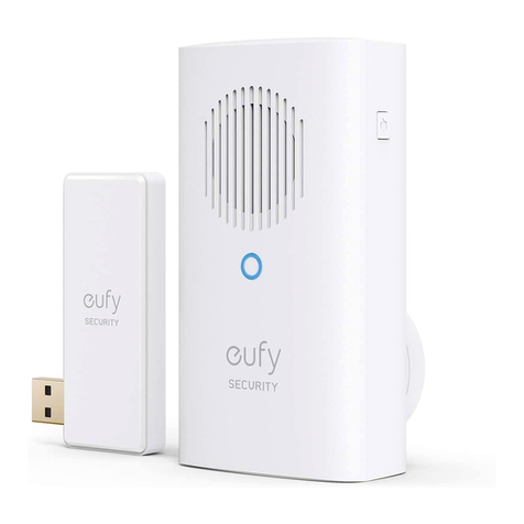
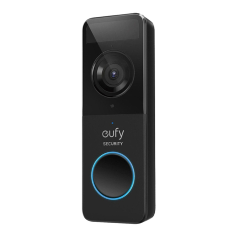
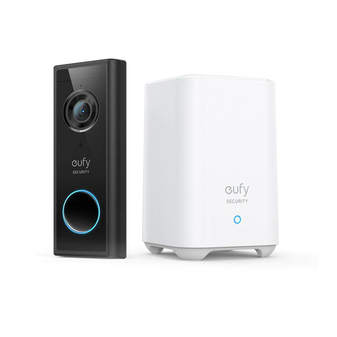
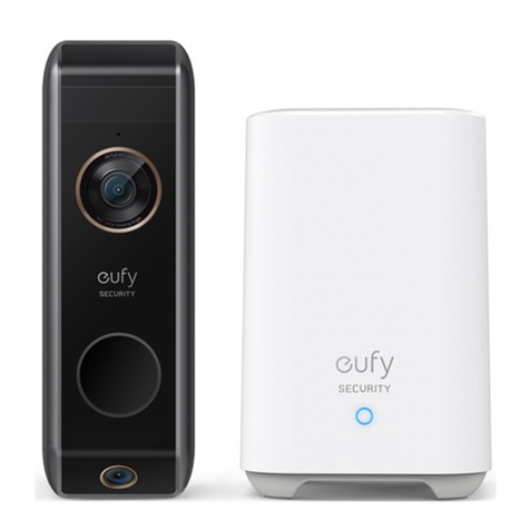
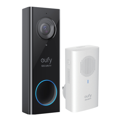
eufy Security 2K User manual

Anker Innovations Limited. All rights reserved. eufy Security and eufy Security Logo are
trademarks of Anker Innovations Limited, registered in the United States and other countries.
All other trademarks are the property of their respective owners.
51005002010 V01
QUICK
START GUIDE
Video Doorbell 2K (Wired)

TABLE OF
CONTENTS
What’s Included 02
How the System Works 03
Getting Started 04
Setting Up the System 06
Finding a Spot For Mounting 07
Installing the Mounting Bracket 11
12 Running Wires through the Wall
13 Connecting the Wires
14 Hooking / Detaching the Doorbell
16 Powering on theVideo Doorbell
17 Notice
105 Customer Service
English 01
Deutsch 21
Español 38
Français 55
Italiano 72
Nederlands 89

01 English English 02
WHAT’S INCLUDED
For Video Doorbell Installation
QSG
Video Doorbell
2K (Wired)
Model:T8200
Quick Start Guide
Doorbell
Detaching Pin
Screw Packs (Anchors
are optional)
Mounting Bracket
(Attached to 15°
Mounting Wedge)
Indoor Power Adapter
15° Mounting
Wedge (Optional)
Screw Hole
Positioning Card
Doorbell Chime
Model:T8740
FCC ID: 2AOKB-T8200
IC: 23451-T8200
Doorbell Chime
Power Pin
Note:
•Doorbell chime power pin varies in different regions.
•Power adapter plug varies in different regions.
HOW THE SYSTEM WORKS
How the System Works
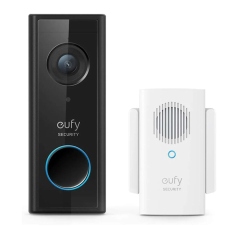
The video doorbell system includes 2 parts. One is the video doorbell at your porch.The other is
the electronic chime plugged into an indoor power socket.The video doorbell is powered by the
provided indoor power adapter, which requires the user to drill a hole in the external wall to run
the power cord from indoors to outdoors.
The video doorbell doesn’t work with the existing doorbell chime. Use the provided electronic
chime instead. When someone rings the doorbell, people in the house will be notied.
Video Doorbell
Doorbell Chime
Tips:
•To make the doorbell system work, running wires through the wall is required. You may
need to hire a qualied electrician at your expense.
•The existing doorbell system is not compatible. If you have an existing doorbell button,
remove it to avoid confusing visitors.

03 English English 04
STEP 1 GETTING STARTED
Prepare the Video Doorbell for Installation
1. Slide in the plug to the switching adapter until you hear a click.
2. Connect the power adapter to the video doorbell.
3. Connect the provided power adapter to a power outlet preferably near the door.Wait for
the video doorbell to power on.
4. Align the doorbell chime power connector with the doorbell chime pin, and turn it clockwise
until it locks in place.
When install,
When install,
When install,
Doorbell Chime
Model:T8740
Doorbell Chime
Power Pin

05 English English 06
STEP 2 SETTING UP THE SYSTEM
Set up the System
1. Download the Eufy Security App from the App Store or Google Play Store and install the App
on your phone.
2. Log into the Eufy Security App.Add your video doorbell (Wired) and scan the QR code for
later installation process. QR code can be found on the back of the video doorbell and at the
rear of the documentation box.
Download EufySecurity App from App
Store or Google Play.
Register or log into your EufySecurity
account.
Add the doorbell and scan this code.
3. Follow the on-screen instructions to connect the video doorbell to your home Wi-Fi, and
complete the setup of the video doorbell.Then you can view live streams on the Eufy Security
app.When you press the doorbell button, the provided electrical chime will sound a ringtone.
Note: If you want to share your video doorbell to your family members and let them
operate the video doorbell via the Eufy Security App, go to Family & Guest from the App’s
side menu and follow the on-screen instructions to share your video doorbell.
STEP 3 FINDING A SPOT FOR MOUNTING
Select Location and Height
1. Take the video doorbell outdoors with the power cord connected to it. It is safe to carry it
around as the output is low voltage(19V DC).
2. Try to nd a location at your front door where you can get an ideal eld of view on live
stream.This is the location where you will mount the video doorbell.The recommended
height for mounting is 48” (1.2 m) from the ground.
If you want to place the doorbell close to a side wall, make sure the wall doesn't show up in
the eld of view. Installing the doorbell too close to a side wall will reect IR light and make
night vision blurry.
1.76m(5’9”)
1.2m (48")
0.3m
(12")
1m
(40")
3. Place the Screw Hole Positioning Card against the wall to mark the location for the power
cord to run through the wall. Position the hole for the power cord to line up with the bottom
half of the Positioning Card’s square hole. Make sure this is where the wire will come out of.

07 English English 08
What is required: Screw Hole Positioning Card
Power Drill with
1/4" (6.35mm) Drill Bit
(User provides it.)
Screw Hole
Positioning-Card
4. Unplug the power adapter and detach the power adapter from the video doorbell.
Drill Holes
1. Drill a hole for the power cord to run through. Use a drill bit that is long enough to fully drill
through the exterior wall.
2. Drill 2 holes to mount the mounting bracket.
•If you are installing the mounting bracket on a wooden wall or board, DO NOT drill
holes.You can screw in the wood directly.
•Anchors are needed if you are installing the mounting bracket on a wall that is made out
of hard materials such as stucco, brick, or concrete.
•Drill on the screw hole positioning card with a 15/64” (6 mm) drill bit.
What is required: Power Drill with 15/64” (6 mm) Drill Bit / Extra Long
Drill Bit
Power Drill with
1/4" (6.35mm) Drill Bit
(User provides it.)
Extra Long Drill Bit 15/64”(6 mm) Drill Bit
Note:
• If you have problems with drilling holes yourself, have a qualied electrician do it. Make sure
that you keep away from wires or pipes within the wall while drilling holes.
•If you have an existing doorbell button at the front door, remove it along with the wires to
avoid confusing visitors by having 2 doorbells.

09 English English 10
Use the 15° Mounting Wedge (Optional)
Use the 15° mounting wedge as a supplementary mounting bracket if you wish to see more on a
specic side.
15°
Without 15° Mounting wedge
Door Door
Video Doorbell Video Doorbell
With 15° Mounting wedge
STEP 4 INSTALLING THE MOUNTING BRACKET
1. Insert the two screws provided through the screw holes or through the 15° mounting wedge
(Install the mounting bracket to the 15° mounting wedge in prior, using long screws).
2. Fasten the screws into the wall tightly.
What is required: Mounting Bracket / Screw Packs / 15° Mounting
Wedge (Optional) / Philips-Head Screwdriver
Mounting Bracket
(Attached to 15° Mounting Wedge)
Screw Packs (Anchors
are optional)
15° Mounting
Wedge (Optional)
Phillips-Head Screwdriver
(User provides it.)
Without 15° Mounting Wedge
Wall Wall
Mounting
Bracket
Mounting
Wedge
Mounting
Bracket
With 15° Mounting Wedge

11 English English 12
STEP 5 RUNNING WIRES THROUGH THE
WALL
Run Wires through the Wall
1. Unplug the power adapter before running wires.
2. Unscrew the terminals on the back of the doorbell to detach the power cord.
3. Slip down the grommet over the adapter wires.
4. Run the power cord through the hole and carefully extend them outside.
• Make sure you have a qualied electrician run the wires if you are not comfortable
with dealing with wires.
• Use the rubber plug or glue to ll the drill holes.
•Use the provided grommet to hold the wires into place. Make sure the wires are
tucked neatly.

13 English English 14
STEP 6 CONNECTING THE WIRES
Connect the Wires
Connect the wires to the two terminals at the back of the doorbell, then tighten the terminal
screws. Wire can connect to any terminal.
•To prevent short-circuit, make sure the wires are not touching each other or
crossing after connecting them to the terminals.
What is required: Power Adapter / Video doorbell / Philips-Head Screwdriver
Power Adapter Video Doorbell 2K (Wired)
Model:T8200
Phillips-Head Screwdriver
(User provides it.)
STEP 7 HOOKING / DETACHING THE
DOORBELL
Hook the Doorbell on the Mounting Bracket
There are 2 thermal conductive pads on the mounting bracket.They're used to conduct heat from
the video doorbell to the metal bracket.
1. Remove the lms on the thermal conductive pads before you mount the doorbell.
2. Hook the doorbell on top of the mounting bracket.
3. Snap the doorbell bottom to the bracket and press it down until it clicks into place.
1 2 3
If the doorbell doesn’t t well, or you want to replace the doorbell, you can detach
the doorbell.

15 English English 16
Detach the Doorbell
1. Use the doorbell detaching pin provided if you wish to detach the doorbell from the mounting
bracket.
2. Press and hold the hole on the bottom of the doorbell and then lift its bottom to take it off.
What is required: Doorbell detaching pin
Doorbell
Detaching Pin
STEP 8 POWERING ON THE VIDEO DOORBELL
1. Plug the power adapter into the wall outlet indoors.
2. Wait for the video doorbell to power up.The doorbell ring turns cyan.You can view the live
stream shot from the video doorbell on the Eufy Security App.
For troubleshooting, check Help on the Eufy Security App.

17 English English 18
NOTICE
FCC Statement
This device complies with Part 15 of the FCC Rules. Operation is subject to the
following two conditions: (1) this device may not cause harmful interference, and (2)
this device must accept any interference received, including interference that may cause
undesired operation.
Warning: Changes or modications not expressly approved by the party responsible
for compliance could void the user's authority to operate the equipment.
Note: This equipment has been tested and found to comply with the limits for a Class
B digital device, pursuant to Part 15 of the FCC Rules. These limits are designed to
provide reasonable protection against harmful interference in a residential installation.
This equipment generates uses and can radiate radio frequency energy and, if not
installed and used in accordance with the instructions, may cause harmful interference
to radio communications. However, there is no guarantee that interference will not
occur in a particular installation. If this equipment does cause harmful interference to
radio or television reception, which can be determined by turning the equipment off
and on, the user is encouraged to try to correct the interference by one or more of
the following measures: (1) Reorient or relocate the receiving antenna. (2) Increase
the separation between the equipment and receiver. (3) Connect the equipment
into an outlet on a circuit different from that to which the receiver is connected. (4)
Consult the dealer or an experienced radio/ TV technician for help.
FCC Radio Frequency Exposure Statement
The device has been evaluated to meet general RF exposure requirements.The device
can be used in xed/mobile exposure condition. The min separation distance is 20cm.
Notice: Shielded cables
All connections to other computing devices must be made using shielded cables to
maintain compliance with FCC regulations.
The following importer is the responsible party.
Company Name: POWER MOBILE LIFE, LLC
Address: 400 108th Ave NE Ste 400, Bellevue,WA 98004-5541
Telephone:1-800-988-7973
This product complies with the radio interference requirements of the European
Community.
Declaration of Conformity
Hereby, Anker Innovations Limited declares that this device is in compliance with the essential
requirements and other relevant provisions of Directive 2014/53/EU.For the declaration of
conformity, visit the Web site:https://www.eufylife.com/.
This product can be used across EU member states.
Do not use the Device in the environment at too high or too low temperature, never expose the
Device under strong sunshine or too wet environment.
The suitable temperature forT8200 is -20°C-50°C.
The suitable temperature forT8740 is 0°C-45°C.
RF exposure information:The Maximum Permissible Exposure (MPE) level has been calculated based
on a distance of d=20 cm between the device and the human body.To maintain compliance with RF
exposure requirement, use products that maintain a 20cm distance between the device and human
body.
CAUTION RISK OF EXPLOSION IF BATTERY IS REPLACED BY AN INCORRECT TYPE.
DISPOSE OF USED BATTERIES ACCORDING TO THE INSTRUCTIONS
Wi-Fi Operating Frequency Range: 2412~2472MHz ;Wi-Fi Max Output Power:18.30 dBm
SUB-1G Frequency range:433.92 MHz; SUB-1G Output Power:7.407 dBm
Bluetooth Operating Frequency Range: 2402~2480MHz; Bluetooth Max Output Power: 0.77 dBm
The following importer is the responsible party (contact for EU matters only).
Importer:AnkerTechnology (UK) Ltd
Importer Address: Suite B, Fairgate House, 205 Kings Road,Tyseley, Birmingham, B11 2AA,
United Kingdom
This product is designed and manufactured with high quality materials and components,
which can be recycled and reused.
This symbol means the product must not be discarded as household waste, and should
be delivered to an appropriate collection facility for recycling. Proper disposal and
recycling helps protect natural resources, human health and the environment. For more
information on disposal and recycling of this product, contact your local municipality,
disposal service, or the shop where you bought this product.

19 English
IC Statement
This device complies with Industry Canada licence-exempt RSS standard(s). Operation
is subject to the following two conditions:
(1) this device may not cause interference, and
(2) this device must accept any interference, including interference that may cause
undesired operation of the device."
Le présent appareil est conforme aux CNR d'Industrie Canada applicables aux
appareils radio exempts de licence. L'exploitation est autorisée aux deux conditions
suivantes:
(1) l'appareil nedoit pas produire de brouillage, et
(2) l'utilisateur de l'appareil doit accepter tout brouillage radioélectrique subi, même si
le brouillage est susceptible d'en compromettre le fonctionnement."
This Class B digital apparatus complies with Canadian ICES-003.
Cet appareil numérique de la classe B est conforme à la norme NMB-003 du Canada.
IC RF Statement:
When using the product, maintain a distance of 20cm from the body to ensure
compliance with RF exposure requirements.
Lors de l'utilisation du produit, maintenez une distance de 20 cm du corps an de vous
conformer aux exigences en matière d'exposition RF.
INHALTS-
VERZEICHNIS
Im Lieferumfang 21
Funktionsweise des systems 22
Erste Schritte 24
Einrichtung des Systems 25
Festlegung der Montageposition 26
30 Installation der Montagehalterung
31 Durchführung des Stromversorgungskabels
durch die Mauer
33 Anschließen der Leiter
34 Einhängen / Aushängen der Türklingel
36 Einschalten derVideo-Türklingel

21 Deutsch Deutsch 22
Im Lieferumfang
Zur Installation der Video-Türklingelanlage
QSG
Modellnummer der
Video-Türklingel 2K
(verdrahtet):T8200
Kurzanleitung
Türklingel-
Lösestift
Schraubensätze (Dübel
optional)
Montagehalterung (am
15°-Montagewinkel
befestigt)
Netzteil (nicht außenraumtauglich!)
15°-Montagewinkel
(optional)
Bohrschablone
Türgong
Modellnummer:T8740
FCC ID: 2AOKB-T8200
IC: 23451-T8200
Türgong-
Steckeraufsatz
Hinweis:
•Die Ausführung des Türgong-Steckeraufsatzes hängt von der jeweiligen Region ab.
•Die Ausführung des Netzteilsteckers hängt von der jeweiligen Region ab.
FUNKTIONSWEISE DES SYSTEMS
Die Video-Türklingelanlage umfasst zwei Komponenten.Zum einen die im Außenraum
anzubringende Türklingel mit Kamera.Zum anderen den in eine Steckdose im Haus
eingesteckten elektronischen Türgong. Die außen angebrachte Video-Türklingel wird von einem
im Innenraum befindlichen Netzteil mit Strom versorgt, weshalb zwecks Durchführung des
Stromversorgungskabels ein Loch in die Hausmauer zu bohren ist.
Die Video-Türklingel kann nicht mit einem bereits vorhandenen Türgong kombiniert werden.
Verwenden Sie stattdessen den mitgelieferten elektronischen Türgong.Sobald jemand die
Türklingel betätigt, werden die Personen im Haus darauf aufmerksam gemacht.
Video-Türklingel
Türgong
Tipps:
•Der Betrieb der Türklingel erfordert die Durchführung des Stromversorgungskabels durch
die Mauer.Eventuell ist die Beauftragung eines Elektrikers auf Ihre Kosten erforderlich.
•Ihre bereits vorhandene Türklingel ist nicht kompatibel.Montieren Sie deshalb Ihre bisherige
Türklingel ab, um eine möglicheVerwirrung Ihrer Besucher zu vermeiden.

23 Deutsch Deutsch 24
SCHRITT 1 – VORBEREITUNG
Vorbereiten der Installation der Video-Türklingelanlage
1. Führen Sie den Stecker ins Schaltnetzteil ein, bis Sie einen Klick hören.
2. Schließen Sie das Netzteil an die Video-Türklingel an.
3. Stecken Sie das Netzteil in eine Steckdose vorzugsweise in der Nähe derTür ein.Warten Sie,
bis sich dieVideo-Türklingel von selbst einschaltet.
4. Platzieren Sie den Türgong-Steckeraufsatz korrekt ausgerichtet auf dem Türgong und drehen
Sie ihn sodann im Uhrzeigersinn, bis er einrastet.
When install,
When install,
When install,
Türgong
Modellnummer:T8740
Türgong
Steckeraufsatz

25 Deutsch Deutsch 26
SCHRITT 2 – EINRICHTUNG DES SYSTEMS
Einrichten des Systems
1. Laden Sie hierzu vom App Store bzw. Google Play Store die Eufy Security-App herunter und
installieren Sie diese auf Ihrem Smartphone.
2. Melden Sie sich bei der Eufy Security-App an.Fügen Sie IhreVideo-Türklingelanlage (verdrahtet)
hinzu und scannen Sie sodann den später noch benötigten QR-Code ein.Den QR-Code
nden Sie auf der Rückseite sowohl der Video-Türklingel selbst als auch der beiliegenden
Dokumentenschachtel.
Download EufySecurity App from App
Store or Google Play.
Register or log into your EufySecurity
account.
Add the doorbell and scan this code.
3. Befolgen Sie die Anweisungen auf dem Display, um dieVideo-Türklingelanlage an Ihr Heim-
WLAN anzuschließen und ihre Einrichtung abzuschließen.Die Eufy Security-App kann nun den
Live-Stream IhrerVideo-Türklingelanlage ausgeben.Wenn Sie die Türklingel betätigen, erzeugt
der mitgelieferte Türgong einen Klingelton.
Hinweis:Wenn auch Ihre Familienangehörigen die Video-Türklingel verwenden und über die
Eufy Security-App Zugriff auf den Live-Stream erhalten sollen, wählen Sie im seitlichen Menü
der App die Option „Familie & Gäste“ und befolgen Sie die Anweisungen auf dem Display,
um diese Benutzer hinzuzufügen.
SCHRITT 3 – FESTLEGUNG DER
MONTAGEPOSITION
Auswählen der geeigneten Stelle und Höhe
1. Nehmen Sie die mit dem Netzteil verbundeneVideo-Türklingel mit nach draußen.Dabei
besteht keinerlei Gefahr, denn die Betriebsspannung beträgt lediglich 19V DC.
2. Suchen Sie im Umfeld Ihrer Haustür eine Stelle, an der die Kamera gemäß Live-Stream ein
ideales Blickfeld abdeckt.An dieser Stelle ist die Video-Türklingel zu installieren.Dabei empehlt
sich eine Installationshöhe von ca. 1,2 m über dem Boden.
Wenn Sie die Türklingel nahe einer Seitenwand anbringen möchten, achten Sie bitte darauf,
dass die Wand nicht im Blickfeld der Kamera liegt.Wird die Türklingel zu nahe an einer
Seitenwand montiert, so hat dies nachts aufgrund der Reektion des IR-Lichts ein unscharfes
Bild zur Folge.
1,76m
1,2m
0,3m1m

27 Deutsch Deutsch 28
3. Drücken Sie die mitgelieferte Bohrschablone an die Wand und markieren Sie die Stelle,
an der das Stromversorgungskabel durch die Mauer verlaufen soll.Bei der Ausrichtung ist
darauf zu achten, dass sich das zu bohrende Kabelloch in der Mauer mittig auf der Höhe
der unteren Hälfte des quadratischen Lochs der Bohrschablone bendet. Dort wird das
Stromversorgungskabel aus der Wand austreten.
Hierzu erforderlich: Bohrschablone
Power Drill with
1/4" (6.35mm) Drill Bit
(User provides it.)
Schraubenloch
Bohrschablone
4. Stecken Sie das Netzteil aus und trennen Sie das Kabel des Netzteils von derVideo-Türklingel.
Bohren der Löcher
1. Bohren Sie ein Loch, in dem das Stromversorgungskabel verlaufen wird.Verwenden Sie hierzu
einen Bohreinsatz, dessen Länge mindestens der Dicke der Außenmauer entspricht.
2. Bohren Sie zudem zwei Löcher für die Installation der Montagehalterung.
•Wenn Sie die Montagehalterung auf einer Holzwand installieren, BOHREN SIE KEINE
LÖCHER!In diesem Fall sind die Schrauben direkt ins Holz einzudrehen.
•Bei der Installation der Montagehalterung auf einer Wand aus hartem Material wie etwa
Putz, Ziegel oder Beton müssen Dübel verwendet werden.
•Verwenden Sie beim Bohren der beiden Löcher mithilfe der Bohrschablone einen
Bohreinsatz mit einem Durchmesser von 6 mm bzw. 15/64 Zoll.
Hierzu erforderlich: Bohrmaschine und zwei Bohreinsätze: ein 6-mm-
bzw. 15/64-Zoll-Bohrer und ein extralanger Bohrer
Bohrmaschine mit
6,35-mm- bzw. 1/4-Zoll-
Bohreinsatz
(User provides it.)
extralangem Bohreinsatz 6-mm- bzw. 15/64-Zoll-
Bohreinsatz

29 Deutsch Deutsch 30
Hinweis:
•Wenn Sie Löcher nicht selbst bohren möchten oder können, beauftragen Sie bitte einen
Handwerker/Elektriker.Achten Sie unbedingt darauf, beim Bohren keine in der Wand
verlegten Stromleitungen oder Rohre zu beschädigen!
•Montieren Sie Ihre bereits vorhandene Türglocke samt Verkabelung ab, um eine Verwirrung
Ihrer Besucher infolge zweier Türglocken zu vermeiden.
Verwenden des 15°-Montagewinkels (optional)
Die zusätzliche Verwendung des 15°-Montagewinkels empehlt sich, wenn die Kamera eher den
Bereich links oder rechts der Türklingel abdecken soll.
15°
Ohne 15°-Montagewinkel
Tür Tür
Video-Türklingel Video-Türklingel
Mit 15°-Montagewinkel
SCHRITT 4 – INSTALLATION DER
MONTAGEHALTERUNG
1. Stecken Sie die beiden mitgelieferten Schrauben durch die Schraubenlöcher der
Montagehalterung bzw. des 15°-Montagewinkels. BeiVerwendung des 15°-Montagewinkels ist
dieser zuvor mittels langer Schrauben an der Montagehalterung zu befestigen.
2. Drehen Sie die beiden Schrauben fest in die Wand ein.
Hierzu erforderlich: Montagehalterung / Schraubensätze /
15°-Montagewinkel (optional) / Kreuzschlitzschraubendreher
Montagehalterung
(am 15°-Montagewinkel befestigt)
Schraubensätze (Dübel
optional)
15°-Montage-
winkel (optional)
Kreuzschlitzschraubendreher
(User provides it.)
Ohne 15°-Montagewinkel
Mauer Mauer
Montage-
halterung
Montage-
Winkel
Montage-
halterung
Mit 15°-Montagewinkel

31 Deutsch Deutsch 32
SCHRITT 5 – DURCHFÜHRUNG DES
STROMVERSORGUNGSKABELS DURCH
DIE MAUER
Durchführen des Stromversorgungskabels durch die Mauer
1. Stecken Sie vor derVerlegung des Stromversorgungskabels das Netzteil aus.
2. Lösen Sie die Anschlussschrauben an der Rückseite der Türklingel, um das
Stromversorgungskabel abnehmen zu können.
3. Schieben Sie die Durchführungstülle über das Stromversorgungskabel.
4. Führen Sie das Stromversorgungskabel innen ins Loch ein und ziehen Sie es außen vorsichtig
heraus.
•Wenn Sie sich beim Umgang mit elektrischen Kabeln unsicher fühlen, beauftragen
Sie bitte einen Elektriker.
•Dichten Sie gebohrte Löcher mit Gummistopfen oder Klebstoff ab.
•Verhindern Sie mit der beiliegenden Durchführungstülle das Verrutschen der Leiter.
Achten Sie darauf, dass die Leiter fest sitzen.

33 Deutsch Deutsch 34
SCHRITT 6 – ANSCHLIESSEN DER LEITER
Anschließen der Leiter
Verbinden Sie die Leiter mit den beiden Anschlüssen an der Rückseite der Türklingel und ziehen
Sie sodann die Anschlussschrauben fest. Das Kabel kann mit jeder Klemme verbunden werden.
•Achten Sie darauf, dass sich die beiden Leiter nach dem Anschließen nicht berühren
bzw. kreuzen, um einen möglichen Kurzschluss zu vermeiden.
Hierzu erforderlich: Netzteil / Video-Türklingel / Kreuzschlitzschraubendreher
Netzteil Video Doorbell 2K (Wired)
Modellnummer:T8200
Kreuzschlitzschraubendreher
(User provides it.)
SCHRITT 7 – EINHÄNGEN / AUSHÄNGEN
DER TÜRKLINGEL
Ein- und Aushängen der Türklingel an der Montagehalterung
An der Montagehalterung benden sich zwei Wärmeleitpads.Sie dienen zur Wärmeableitung von
der Türklingel auf die metallene Montagehalterung.
1. Ziehen Sie vor der Montage der Türklingel die Schutzfolie von den Wärmeleitpads ab.
2. Hängen Sie die Türklingel am oberen Ende der Montagehalterung ein.
3. Drücken Sie dann das untere Ende der Türklingel Richtung Mauer, bis sie mit einem Klick
einrastet.
1 2 3
Wenn die Türklingel nicht gut sitzt oder ausgetauscht werden soll, können Sie diese
mithilfe des Lösestifts abnehmen.

35 Deutsch Deutsch 36
Aushängen der Türklingel
1. Verwenden Sie zum Abnehmen der Türklingel von der Montagehalterung den mitgelieferten
Lösestift.
2. Stecken Sie mit einer Hand den Lösestift in das Loch an der Unterseite derTürklingel ein und
ziehen Sie mit der anderen Hand das untere Ende der Türklingel von der Mauer weg.
Hierzu erforderlich: Türklingel-Lösestift
Türklingel-
Lösestift
SCHRITT 8 – EINSCHALTEN DER VIDEO-
TÜRKLINGEL
1. Stecken Sie das Netzteil in die Steckdose nahe der Haustür ein.
2. Warten Sie, bis sich dieVideo-Türklingel von selbst einschaltet.Die ringförmige
Klingeltasteneinfassung leuchtet jetzt blaugrün.Die Eufy Security-App kann nun den Live-
Stream IhrerVideo-Türklingelanlage ausgeben.
Tipps zur Fehlerbehebung finden Sie in der Hilfe der Eufy Security-App.
Table of contents
Languages:
Other eufy Security Accessories manuals

eufy Security
eufy Security HomeBase 2 User manual

eufy Security
eufy Security T8203 User manual

eufy Security
eufy Security T8900 User manual

eufy Security
eufy Security 906290 User manual

eufy Security
eufy Security T8220 User manual

eufy Security
eufy Security T8200 User manual

eufy Security
eufy Security T8910 User manual

eufy Security
eufy Security T8222 User manual

eufy Security
eufy Security T8900 User manual

eufy Security
eufy Security T8221 User manual