Evoca Group Snakky SL User manual

INSTALLATION, USE AND MAINTENANCE MANUAL
UK English
Snakky SL
DOC. NO. H 204U 00
EDITION 1 2003-03


Italiano Si dichiara che la macchina, descritta nella targhetta di identicazione, è
conforme alle disposizioni legislative delle Direttive Europee elencate a lato e suc-
cessive modiche ed integrazioni.
English The machine described in the identication plate conforms to the legisla-
tive directions of the European directives listed at side and further amendments and
integrations
English The harmonised standards or technical specications (designations) which
comply with good engineering practice in safety matters in force within the EU have
been applied are:
Français La machine décrite sur la plaquette d’identication est conforme aux
dispositions légales des directives européennes énoncées ci-contre et modications
et intégrations successives
Español Se declara que la máquina, descrita en la etiqueta de identicación, cum-
ple con las disposiciones legislativas de las Directrices Europeas listadas al margen
y de sus sucesivas modicaciones e integraciones
Português Declara-se que a máquina, descrita na placa de identicação está con-
forme as disposições legislativas das Diretrizes Européias elencadas aqui ao lado e
sucessivas modicações e integrações
Deutsch Das auf dem Typenschild beschriebene Gerät entspricht den rechts aufge-
führten gesetzlichen Europäischen Richtlinien, sowie anschließenden Änderungen
und Ergänzungen
Nederlands De machine beschreven op het identicatieplaatje is conform de
wetsbepalingen van de Europese Richtlijnen die hiernaast vermeld worden en latere
amendementen en aanvullingen
Italiano Le norme armonizzate o le speciche tecniche (designazioni) che sono
state applicate in accordo con le regole della buona arte in materia di sicurezza in
vigore nella UE sono:
Français Les normes harmonisées ou les spécications techniques (désignations)
qui ont été appliquées conformément aux règles de la bonne pratique en matière de
sécurité en vigueur dans l’UE sont :
Deutsch Die harmonisierten Standards oder technischen Spezikationen (Bestim-
mungen), die den Regeln der Kunst hinsichtlich den in der EU geltenden Sicherheits-
normen entsprechen, sind:
Español Las normas armonizadas o las especicaciones técnicas (designaciones)
que han sido aplicadas de acuerdo con las reglas de la buena práctica en materia de
seguridad vigentes en la UE son:
Português As normas harmonizadas ou as especicações técnicas (designações)
que foram aplicadas de acordo com boas regras de engenharia em matéria de seg-
urança em vigor na UE são:
Nederlands De geharmoniseerde normen of technische specicaties (aanwijzingen)
die toegepast werden volgens de in de EU van kracht zijnde eisen van goed vakman-
schap inzake veiligheid zijn de volgende:
DICHIARAZIONE DI CONFORMITA’
DECLARATION OF CONFORMITY
DÉCLARATION DE CONFORMITÉ
KONFORMITÄTSERKLÄRUNG
DECLARACIÓN DE CONFORMIDAD
DECLARAÇÃO DE CONFORMIDADE
VERKLARING VAN OVEREENSTEMMING
Targhetta di identicazione
Identication label
Valbrembo, 01/01/2012
ANDREA ZOCCHI
C.E.O
Direttive europee
European directives
Sostituita da
Repealed by
2006/42/EC
73/23/EC + 93/68/CE 2006/95/CE
89/336/EC + 92/31/CE +
93/68/CE
2004/108/EC
90/128/EC 2002/72/CE
80/590/EEC and 89/109/
EEC
EC 1935/2004
EC 10/2011
2002/96/EC
Norme armonizzate /
Speciche tecniche
Harmonised standards
Technical specica-
tions
EN 60335-1:2002 + A1:2004 + A11:2004 + A12:2006
+ A2:2006+ A13:2008
EN 60335-2-75:2004 + A1:2005 + A11:2006 +
A2:2008 + A12:2010
EN 62233:2008
EN 55014-1: 2006 + A1: 2009
EN 55014-2: 1997 + A1: 2001 + A2: 2008
EN 61000-3-2: 2006 + A1: 2009 + A2: 2009
EN 61000-3-3: 2008
EN 61000-4-2: 2009
EN 61000-4-3: 2006 + A1: 2008
EN 61000-4-4: 2004
EN 61000-4-5: 2006
EN 61000-4-6: 2009
EN 61000-4-11: 2004
Il fascicolo tecnico è costituito presso:
The technical le is compiled at:
N&W GLOBAL VENDING S.p.A.

Declaration of conformity
The declaration of conformity with the European Direc-
tives and Standards provided for by the laws in force
is supplied by the rst page of this manual, which is an
integral part of the machine.
It is declared that the machine described by
the identication plate is in compliance with the
provisions of the European Directives, its sub-
sequent amendments and integrations as well as with
the harmonised standards or technical specications
(designations) applied in compliance with the safety
rules of good practice enforced in the EU and listed on
the same page.
Warnings
f o r u s e
The machine can be used by children and by people
having reduced physical, sensorial or mental skills under
the supervision of people responsible for their safety or
specically trained on the use of the machine. Children
shall be prevented from playing with the machine by the
people in charge of their supervision.
f o r s c r a p p i n g
The symbol shows that the machine can not
be disposed of as common waste, but it must
be disposed of as it is established by the
2002/96/CE (Waste Electrical and Electronics
Equipments - WEEE) European Directive and
by the national laws arising out of it in order to prevent
any negative consequence for environment and human
health.
The dierentiated collection of the machine at the end of
its life is organised and managed by the manufacturer.
For the correct disposal of the machine contact the sales
point where you have purchased the machine or our
after-sales service.
The unlawful disposal of the machine implies the appli-
cation of the administrative sanctions provided for by the
rules in force.
Attention!
If the machine is equipped with a cooling system, the
cooling unit contains HFC-R134a uoridised greenhouse
eect gas ruled by the Kyoto protocol, the total heating
potential of which is equal to 1300.

1
© by NECTA VENDING SOLUTIONS SpA 0303 204-00
TABLE OF CONTENTS
INTRODUCTION PAGE 2
IDENTIFICATION OF THE VENDING MACHINE PAGE 2
IN CASE OF FAILURE PAGE 2
TRANSPORT AND STORAGE PAGE 2
USING THE VENDING MACHINE PAGE 3
POSITIONING THE VENDING MACHINE PAGE 3
WARNING FOR INSTALLATION PAGE 3
PRECAUTIONS IN USING THE MACHINE PAGE 3
WARNING FOR SCRAPPING PAGE 4
TECHNICAL SPECIFICATIONS PAGE 4
ACCESSORIES PAGE 4
POWER CONSUMPTION PAGE 4
VARIABLE COMBINATION LOCK PAGE 5
LOADING AND CLEANING PAGE 6
MAIN SWITCH PAGE 6
CONFIGURING THE SPIRALS PAGE 6
HYGIENE AND MAINTENANCE PAGE 7
LOADING PRODUCTS PAGE 8
INSTALLATION PAGE 9
UNPACKING THE VENDING MACHINE PAGE 9
MASTER/SLAVE BANK PAGE 9
CONNECTING THE VENDING MACHINES PAGE 10
CONNECTING THE NUMERIC KEYPAD PAGE 10
ASSEMBLING THE VENDING MACHINE PAGE 11
CONNECTING TOTHE POWER SUPPLY PAGE 11
CONTROLS AND INFORMATION PAGE 12
INTERNAL COMPONENTS PAGE 12
MAIN SWITCH PAGE 12
BANK CONFIGURATION PAGE 12
OPERATING MODES PAGE 13
USER INTERFACE PAGE 13
NORMAL OPERATING MODE PAGE 13
FILLER MENU PAGE 13
STATISTICS PAGE 14
PRICES FOR SINGLE SELECTIONS PAGE 14
SPECIAL SELECTIONS PAGE 14
TEST PAGE 15
EVADTS TRANSFER PAGE 15
TECHNICIAN MENU PAGE 16
PRESENT FAILURES PAGE 17
PROGRAMMING PARAMETERS PAGE 18
SPIRALS/SELECTIONS PAGE 18
PHOTOCELLS PAGE 19
DISPENSING COMPARTMENT LOCK PAGE 19
REFRIGERATION PARAMETERS PAGE 19
DISPLAY PAGE 19
MISCELLANEOUS PAGE 19
STATISTICS PAGE 20
TEST PAGE 20
MACHINE INFORMATION PAGE 21
EVADTS CODES PAGE 21
INITIALISING PAGE 21
MAINTENANCE PAGE 22
PRINTED BOARD FUNCTIONS
AND INDICATOR LIGHTS PAGE 22
SOFTWARE UPDATE PAGE 22
CONFIGURINGTHETRAYS PAGE 23
PRODUCT SPACERS PAGE 23
PRODUCT EJECTOR PAGE 23
REPLACING THE SPIRALS PAGE 23
REMOVING THE TRAYS PAGE 23
CHANGING THE NUMBER OF TRAYS PAGE 24
CHANGING THE TRAY CONFIGURATION PAGE 24
POWER SUPPLY UNIT PAGE 25
ACCESS TO THE COOLING UNIT PAGE 25
MENU SUMMARY PAGE 26
WIRING DIAGRAM PAGE 49

INTRODUCTION
This technical documentation is part and parcel of
the machine and must always follow the machine in
case it is moved or ownership is transferred, so as
to allow consultation by dierent operators.
Before starting installation and using the machine, it is
rst necessary to carefully read and understand the in-
structions contained in this manual, as they oer impor-
tant information on installation safety, operating instruc-
tions and maintenance.
Th i s m a n u a l i s d i v i d e d i n T o T h r e e c h a p T e r s .
The rst chapter describes the loading and routine
maintenance operations which are carried out in areas of
the machine accessible with simple use of the door key,
without using any other tools.
The second chapter contains the instructions for cor-
rect installation and all information necessary for opti-
mum use of the machine.
The third chapter describes maintenance operations
which involve the use of tools to access potentially dan-
gerous areas.
The operations described in the second and third chap-
ters must be carried out only by personnel who have the
specic knowledge of the machine functioning from a
point of view of electrical safety and health regulations.
IDENTIFICATION OF THE VENDING
MACHINE AND ITS CHARACTERISTICS
Every machine is identied by its own serial number,
indicated on the rating plate attached inside the cabinet
on the right side.
This plate (see g. 1) is the only one acknowledged by
the manufacturer as the identication of the apparatus,
and carries all the data which readily and safely give
technical information supplied by the manufacturer. It
also assists in the spare parts management.
IN CASE OF FAILURE
In most cases, any technical problems are corrected by
small repair operations; however, before contacting the
manufacturer we recommend that this manual be read
carefully.
Should there be serious failures or malfunctions, contact
the following:
N&W GLOBAL VENDING S.p.A.
Via Roma 24
24030 Valbrembo
Italy - Tel. +39 - 035606111
TRANSPORT AND STORAGE
To prevent any damage, special care should be taken
when loading or unloading the machine.
The machine can be lifted by a motor-driven or manual
forklift truck, and the forks are to be placed underneath
the machine from the side clearly indicated by the sym-
bol on the cardboard package.
Do not:
overturn the vending machine;-
drag the vending machine with ropes or similar;-
lift the vending machine by its sides;-
lift the vending machine with slings or ropes;-
shake the vending machine.-
The machine should be stored in a dry room where the
temperature remains between 0° C and 40 °C.
Avoid stacking machines one on top of the other and
always keep it upright as indicated by the arrows on the
packing.
Refrigeration system class
Absorbed power
Operating voltage
Model
Product code
Type and amount of refrigerant gas
Current
Frequency
Serial number
Type

3
© by NECTA VENDING SOLUTIONS SpA 0303 204-00
USING THE VENDING MACHINE FOR
PACKAGED PRODUCTS
The machine can operate only as “slave”, which means
thatithas to be connected to a “master” machine thatcan
control its functions, since the reduced electronics does
notpermitautonomousoperationofthisvendingmachine.
Thevariousfunctionsareprogrammedthroughtheselec-
tionkeypadof the“master”machine,whichmustbeofthe
numeric combination type.
Allmodels are equipped with variableconfiguration trays,
addingorremovingdividers,spiralsandratiomotors;there-
fore the machine can be easily suited to specific needs.
All trays are preset for the operation of up to 6 selections
(maximum setting).
Thecompartmentsareequippedwithindependentmotors
and spirals; each selection will continue its operation
autonomously even if the other selections are discon-
nected.
POSITIONING THE VENDING MACHINE
The vending machine is not suitable for outdoor installa-
tion.Itmustbepositionedinadryroomwherethetempera-
tureremainsbetween2°Cand32°C,andnotwherewater
jets are used for cleaning (e.g. in large kitchens, etc.).
The machine can be used only in a bank with another
machine that can control the “master/slave” function.
The same “master” machine can control a bank with two
machines operating as “slave”.
Theventilationsystemallowsthebackpanel tobeleaned
against the wall, thus saving space, as air is drawn from
under the machine and exhausted through a grille on the
right-hand side. However, the grille must be completely
free without obstructions to the airflow for at least 40 cm.
If this were not possible, the spacer supplied with the
machine must be fitted to ensure the required distance
from the wall (see Fig. 2).
Warning!
Incorrectventilationmaycompromisetheproperfunc-
tioning of the cooling unit.
The machine should be positioned with a maximum incli-
nation of 2°.
Ifnecessaryprovideproperlevellingbywayoftheadjust-
able feet included.
WARNING FOR INSTALLATION
The machine installation and the following mainte-
nance operations should be carried out by qualified
personnel only, who are trained in the correct use of
the machine according to the standards in force.
The machine is sold to be connected to a “master” ma-
chine.
The composition of the bank of machines and assembly
must be carried out only in accordance with the manufac-
turer’s instructions, where necessary using the approved
kits.
The integrity of the machine and compliance with the
standardsoftherelevantsystemsmustbecheckedat
least once a year by qualified personnel.
PRECAUTIONS IN USING THE MACHINE
The following precautions will assist in protecting the
environment:
- use biodegradable products only to clean the machine;
- adequately dispose of all containers of the products
used for loading and cleaning the machine;
- keep the machine away from heat sources;
- regularly check the condition of the door seal to limit
any heat dispersion;
- limit as much as possible door opening time during
loading operations to avoid temperature increase
inside the cabinet and subsequent power consumption.
Fig. 2
1 - Securing holes
2 - Spacer
3 - Fastening screws
4 - Can-bus connection cable
4
© by NECTA VENDING SOLUTIONS SpA 0303 204-00
WARNING FOR SCRAPPING
Wheneverthemachineistobescrapped,thelawsinforce
regarding environment protection should be strictly ob-
served. More specifically:
- ferrous and plastic materials and the like are to be
disposed of in authorized areas only;
- insulating materials should be recovered by qualified
companies.
- the gas inside the cooling unit, regardless of the type
(see the identification plate), should be recovered by
qualified companies by means of special equipment.
TECHNICAL SPECIFICATIONS
Power supply voltage 230 V~
Power supply frequency 50 Hz
Absorbed power 345 W
Max. operating conditions:
Ambienttemperature 32 °C
Relative humidity 65 %
Refrigeration system:
Compressor’s refrigeration output 320 W
Fan-forced evaporator
Programmable defrosting cycle
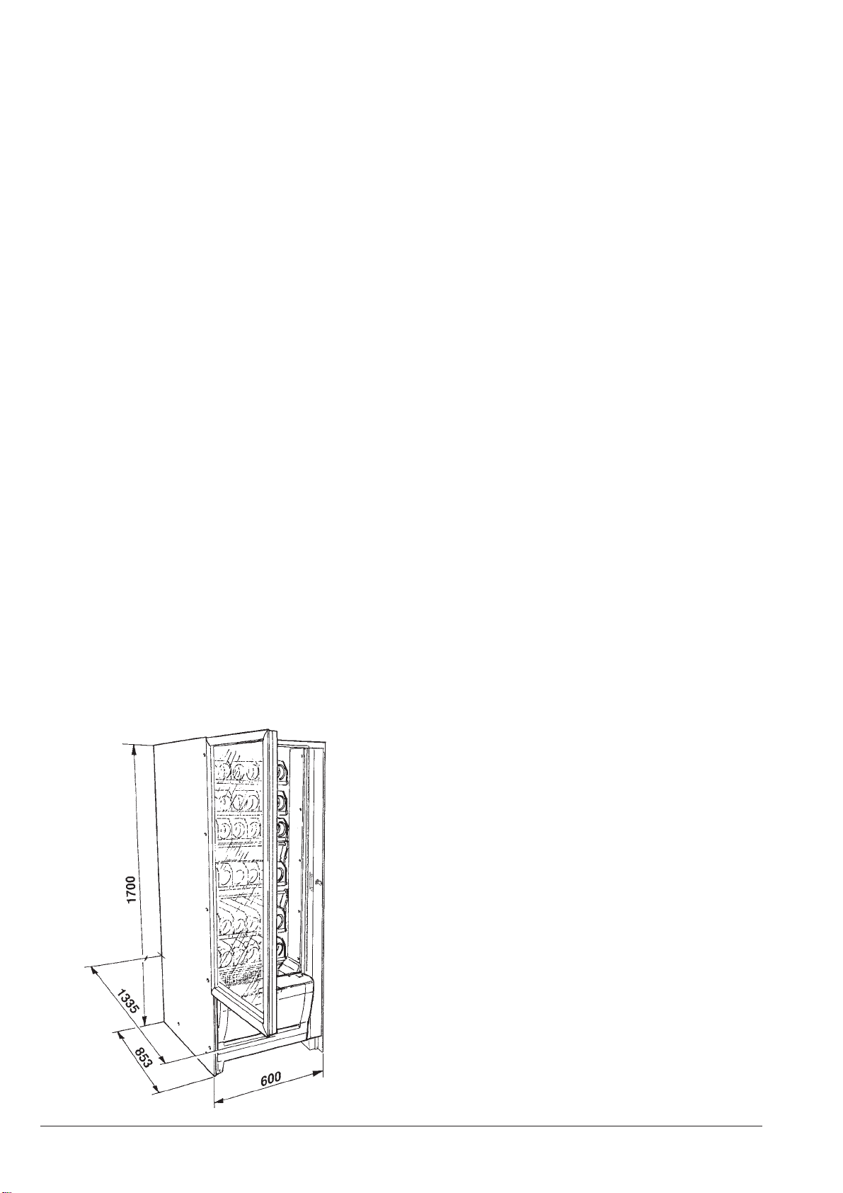
DIMENSIONS
Height 1700 mm
Width 600 mm
Depth 854 mm
Overall depth with door open 1335 mm
Weight 165 Kg
CONTROLS AND SAFETY DEVICES
- Main switch
- Timeout for power supply to dispensing motors
- Compressor overheating protection
- Line fuses
- Fuses on transformer primary and secondary windings
ACCESSORIES
A wide range of accessories can be installed on the
machine, to vary its performance.
Theinstallationkitsaresuppliedwiththeirowninstallation
and test instructions, which must be strictly observed to
ensure the machine safety.
Installationandthefollowingtestingoperationsmust
be carried out exclusively by personnel who have a
specific knowledge of the machine functions from a
point of view of electrical safety and health regula-
tions.
POWER CONSUMPTION
The machine power consumption depends on many fac-
tors, such as temperature and ventilation of the room
where it is installed, temperature of loaded products,
internal temperature of the refrigerated box.
Under average conditions, and namely:
- ambient temperature: 20 °C
- refrigerated box temperature: 8 °C
- temperature of loaded products
(machine completely empty) 20 °C
the following power consumption levels resulted:
- hourly stand-by power consumption 151 Wh
The above power consumption calculated from average
data should only be taken as an indication.
Fig. 3

5
© by NECTA VENDING SOLUTIONS SpA 0303 204-00
CHANGEABLE COMBINATION LOCK
Some machine models are fitted with a changeable com-
bination lock.
Thelock is supplied with twosilvercolour keys to be used
for normal opening and closing.
The lock can be customised by using a kit, available as
accessory,whichpermitsthecombinationofthelocktobe
changed.
This kit includes a change key (black) for the current lock
combination as well as the change (gold) and use (silver)
keys for the new combination.
Setsof change and usekeyswithother combinations can
be supplied on request.
Additional sets of use keys (silver) may be requested,
indicating the combination stamped on the keys.
Generally, only the use key (silver) is used, while the
combination change keys (gold) can be kept as spares.
Do not use the change key for normal opening, as it
may damage the lock.
Fig. 4
To change combination do as follows:
- open the machine door to avoid forcing the rotation;
- lightly lubricate the inside of the lock with a spray;
- insert the current change key (black) and rotate to the
change position (reference notch at 120°);
- remove the current change key and insert the change
key (gold) with the new combination;
- rotate to the close position (0°) and remove the change
key.
The lock will now have the new combination.
Thekeys withthe old combinationcannot beused for
the new combination.

6
© by NECTA VENDING SOLUTIONS SpA 0303 204-00
Chapter 1
LOADING AND CLEANING
MAIN SWITCH
Byopeningthesidedoor,accesscanbegainedtothemain
switch (see Fig. 5) that disconnects the power from the
machine electrical system to allow the loading and clean-
ing operations in full safety.
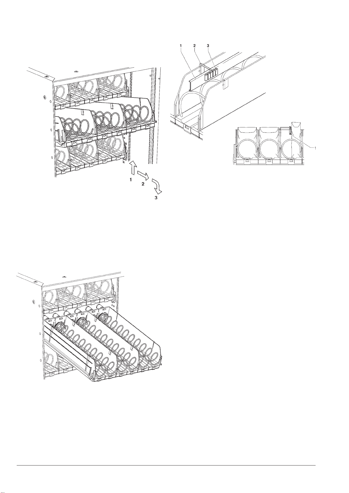
Fig. 7
1 - 180° rotation spiral
2 - Divider
A - Spiral pitch
B - Maximum product size
CONFIGURING THE SPIRALS
Accordingtothesizeoftheproductstobedispensed,each
machine can be fitted with a variable number of trays
(maximum6),productcompartmentsandwithdispensing
spirals of different pitch.
Fig. 5
1 - Door opening grip
2 - Trays
3 - Lock
4 - Product passage photocells (optional)
5 - Product dispensing compartment
6 - Main switch
Fig. 6
1 - Tray
2 - Mobile walls
3 - Right-hand spiral
4 - Left-hand spiral
Thisvendingmachineshouldonlybeusedtoselland
dispensepackaged productsthat do not need refrig-
eration to be preserved.
Strictlycomplytotheproducer’sspecificationsregarding
storage method and expiry date for each product.
Any other use is unsuitable and thus potentially
dangerous.
Thespiralscanbehousedeitherin152mmcompartments
(two spirals, right-hand and left-hand, in each compart-
ment)forlargesizeproducts,orinto75mmcompartments
(oneright-handspiral ineachcompartment)forsmallsize
products.
Whendispensingsticksofcandiesorsimilarproducts,itis
possibleto settherotation of thespiralsto 180°insteadof
360° for the 75 mm compartments and use a special right
hand spiral fitted with a divider (see Fig. 7), doubling the
capacity of the compartments.

7
© by NECTA VENDING SOLUTIONS SpA 0303 204-00
Itisalsopossible toinserta dividerinthe alreadyinstalled
spirals (see Fig. 8). The spirals can be positioned with 22,5 degree steps by
pulling them towards the front and rotating them in the
direction of ejection.
Normally, the products can be dispensed without any
problems when the spiral end is in the lower centre posi-
tion.
The maximum size (see Fig. 6) and the number of prod-
ucts,thepitchandthedirectionofrotationofthespiralsare
shown in the following table.
The machine is supplied with a table indicating the opti-
mum setting for the different product types.
Theconfigurationcanbechangedfollowingtheindications
of the relevant chapter.
HYGIENE AND MAINTENANCE
According to current health and safety regulations, the
operator of vending machines is responsible for their
hygiene and cleaning.
It is advisable to use sanitising products (chlorine based
detergent or similar) to clean all surfaces even if not in
direct contact with food.
Some parts of the machine can be damaged by strong
detergents.
The manufacturer declines all responsibility for damage
caused
by non-compliance with the above instructions or by the
use of strong or toxic chemical agents.
Under no circumstances should sprayed water be
used.
Before any maintenance operation always switch the
machine off.
Asstandardfeatureorusingspecialkits,themachinecan
be equipped with small compartments, suitable for dis-
pensing cans, plastic bottles up to 69 mm dia., 0.2 litre
Tetra-Paks.
The compartments equipped in this way can be recog-
nisedbytheshapeoftheproductsupportbracket(seeFig.
9).
Some bottle types can be dispensed without using the
supports.
Most bottles can be dispensed without using any special
accessories, loading the bottles up side down, so that the
cap slides in the compartment channel.
Fig. 8
1 - Spiral
2 - Divider
A.mm B.mm °N
08676
46067
45058
642401
046311
430331
036241
420291
)°081(420291+91
Fig. 9
1 - Compartment’s channel
2 - Product raised support
8
© by NECTA VENDING SOLUTIONS SpA 0303 204-00
LOADING PRODUCTS
- Remove one tray at a time, lifting it and pulling it past
the retaining slide. The upper trays will tilt downwards
to facilitate loading.
Fig. 11
Fig. 10
- Load all products starting at the front, without inserting
products with a temperature above 30°C, ensuring that
all spaces are filled. The bottom of the product must
rest at the bottom of the compartment with the label
facing the window so that it can be identified.
Allproductsshouldloadeasily,donotinsertproducts
which are too large for the space.
- Push in the trays completely, ensuring that they go
past the retaining slide.
The sealed end of bags may be caught under the spiral,
preventing the free fall of the product.
Fold the seal towards the front of the unit and upwards
before inserting the product in the spiral.
More fragile products must be placed on the lower
trays to prevent damage when they drop.
Verythinproductscanbedispensedonlyusingthespecial
spacer.
NOISE LEVEL
The continuous, weighted equivalent acoustic pressure
level is below 70 dB.
START-UP
Each time the machine is started, the number of trays
connected to the system are checked by the electronic
controls.
Also the number of actually connected compartments is
checked.
OPERATING TEMPERATURE
The machine can operate only where the ambient tem-
perature is between 2°C and 32°C.
The cabinet temperature can be adjusted between 8°C
and 20°C.
Fig. 12
1 - Product spacer
2 - Brackets
3 - Adjustment notches

9
© by NECTA VENDING SOLUTIONS SpA 0303 204-00
Chapter 2
INSTALLATION
The machine installation and the following mainte-
nance operations should be carried out by qualified
personnel only, who are trained in the correct use of
themachineandareawareofthespecificrisksofsuch
operations.
Themachineis notsuitable foroutdoorinstallation, it
mustbeinstalledinadryroomwherethetemperature
remains between 2°C and 32°C.
It cannot be positioned where water jets are used for
cleaning (e.g. in large kitchens, etc.).
The machine should be positioned with a maximum
inclination of 2°.
The relative humidity must not exceed 65%.
UNPACKING THE VENDING MACHINE
After removing the packing, ensure that the machine is
intact.
If the vending machine is found to be damaged, immedi-
ately inform the carrier and do not use the machine.
No packing elements (i.e. plastic bags, polystyrene
foam, nails, etc.) should be left within the reach of
children, as they are potentially dangerous.
Packing materials must be disposed of in authorised
containersandtherecyclableonesmustberecoveredby
qualifiedcompanies.
If the vending machine had been laid down during
transport,allowatleastone hour beforeconnectingit
to the mains.
MASTER/SLAVE BANK
Since the machine does not have its own user interface,
itmustbeconnectedtoanothervendingmachinethathas
master functions.
Themastermachinemusthaveanumerickeypadtoallow
programming operations and vending for the bank of
machines.
It is also possible to configure as master those vending
machines that have direct selection buttons, using the
numeric keypad supplied with the machine.
Thebankcanbecomposedofthreevendingmachines,of
which one is master and two are slave; in this case the
selectionnumbersofthetwoslave machinesmustbeset
with three digits.
The typical configurations are therefore as follows:
A - Master with direct buttons (adding the numeric
keypad) + slave without interface; all components
required for this configuration are supplied with the
machine.
Fig. 13
1 - Vending machine without interface
2 - Vending machine with direct buttons
3 - Vending machine with numeric keypad
4 - Additional numeric keypad

10
© by NECTA VENDING SOLUTIONS SpA 0303 204-00
Fig. 14
1 - Pre-cut section
2 - Can-bus connector
3 - Connector’s holder plate
4 - Machine securing hole
5 - Power supply unit cover
6 - Actuation board
7 - C.P.U. Board
8 - Keypad cable
9 - Numeric keypad
10 - Slot for keypad flat cable
Using special kits also the following configurations are
possible:
B - Master with numeric keypad + slave without inter-
face
B - Master with direct buttons (adding the numeric
keypad) + 2 slaves without interface
B - Master with numeric keypad + slave with direct
buttons + slave without interface
Important notice!
When assembling the bank of machines the ventila-
tion grilles of the cooling units must be taken into
account.
Shouldthegrillesbecovered,thespacersuppliedwiththe
machine must be fitted (see Fig. 2).
Specifickitsareavailableforthedifferentmodelstoclose
the empty space between cabinet and wall.
Warning!
Do not move the vending machines when already
assembled.
It is not possible to lift them or push them and slide them
along the floor, nor can they be transported, without
separating the various machines.
CONNECTING THE VENDING MACHINES
Ensure that the master vending machine is connected to
the power supply.
- Remove the pre-cut section of the external back panel
and eliminate any burrs on the sheeting.
- Insert the can-bus cable inside the cabinet and secure
connector’s holder plate to the back panel with 2
screws.
- From the front of the vending machine, drill a 10-mm
diameter hole on the left side of the cabinet.
- Remove the cover from the power supply unit and
connect the can-bus cable terminal to connector “J4”
or “J6” on the actuation board. Secure the cable and
replace the parts that were removed.
CONNECTING THE NUMERIC KEYPAD
If the master machine is of the type with direct selection
buttons, the numeric keypad (see Fig. 18) must be in-
stalled as follows:
- by removing the pre-cut section make a hole on the
door for the numeric keypad wiring.
- attach the keypad, taking care not to leave any air
bubbles.
- connect the keypad cable to connector J16 on the
C.P.U. board
11
© by NECTA VENDING SOLUTIONS SpA 0303 204-00
CONNECTING THE MACHINE
TO THE POWER SUPPLY
Themachineisdesignedtooperateunderasingle-phase
230 V~ voltage and is protected by T6.3 A fuses.
Apowersupplyoutletmustbeprovidedforeachmachine
of the bank.
Itisnotpossibletoconnectmorethanonemachineto
the same power outlet.
Before making the connection, ensure that the rating of
each machine corresponds to that of the power grid, and
more specifically:
- the supply voltage rating must be within the range
recommended for the connection points;
- the main switches should be capable of withstanding
the peak load required, and at the same time ensure
proper omnipolar disconnection from the power grid
with an opening gap of the contacts of at least 3 mm.
Theswitches,thepoweroutletsandtheplugsmustbe
located in an easily accessible position.
Theelectricalsafetyofthemachineisensuredonlywhen
itis correctlyearthedaccording tothesafety standardsin
force.
This fundamental safety requirement must be duly
verified, and if in doubt the system must be carefully
tested by qualified technicians.
Thepowersupplycableisofthetypewithafixedplug.Any
replacement of the power cable (see Fig. 16) should be
made by qualified and suitably trained personnel only
using cables type HO5 RN - F or HO5 V V-F or H07 RN-
F with a 3x1-1.5 mm2section.
ASSEMBLING THE VENDING MACHINES
To assemble master and slave vending machines do as
follows:
- Check that side ventilation grilles of the machines
equipped with a cooling unit are completely free.
Should the ventilation grilles be covered, even partially,
due to the layout to be adopted, it will be necessary to
fit the spacer (see Fig. 15) supplied with the machine.
Important notice!
Thebankofmachinesshouldinanycasebeatleast4cm
from the wall so that correct ventilation may be ensured.
- Ensure that the inclination of the machines does not
exceed 2°; If necessary provide proper levelling by
way of the adjustable feet included; the feet must be
adjusted to keep the machines side by side at the
same height.
- Secure the clamping bracket to the left side of the
master machine and position it next to the vending
machine; connect the connectors of the external can-
bus cable.
- Line up the front of the two vending machines, taking
care not to pull the external can-bus cable and not to
damage the cabinet with the protruding clamping
bracket.
- Secure the clamping bracket to the top panel of the
slave machine. Secure the two vending machines with
the screw at the base.
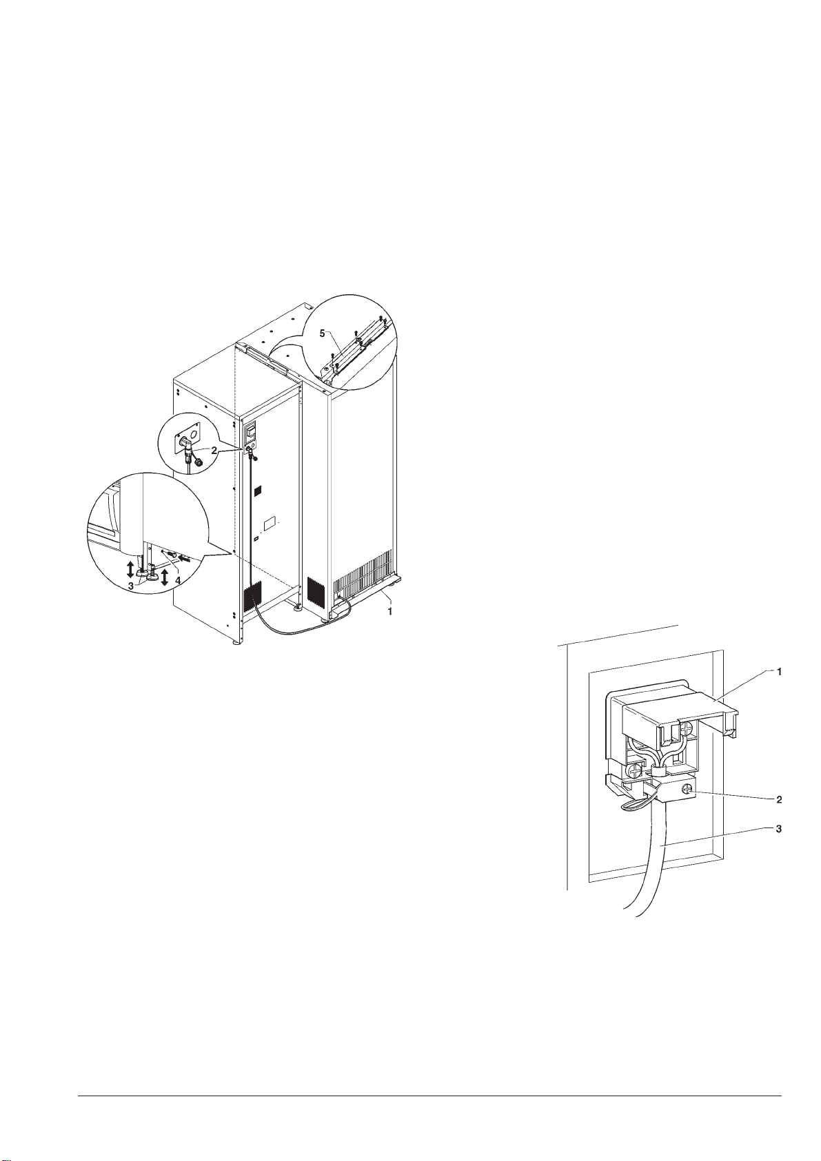
Fig. 15
1 - Spacer
2 - Can-bus cable connectors
3 - Adjustable feet
4 - Securing hole (to be drilled)
5 - Machine clamping bracket
Fig. 16
1 - Lift cover
2 - Cable clamp
3 - Power supply cable
Do not use adapters, multiple sockets and/or exten-
sions.
THE MANUFACTURER DECLINES ALL RESPONSI-
BILITY FOR ANY DAMAGE CAUSED BY NON-COM-
PLIANCE WITH THE ABOVE MENTIONED PRECAU-
TIONS.

12
© by NECTA VENDING SOLUTIONS SpA 0303 204-00
Fig. 17
1 - Product dispensing compartment housing
2 - Cooling unit condenser
3 - Cooling unit evaporator
4 - Cold airflow grilles
5 - Removable grille cover
6 - Tray guides
7 - Product passage photocells
8 - C.P.U. board
9 - Transformer fuses
10 - Mains fuses
11 - Main switch
CONTROLS AND INFORMATION
The machine can be used only as slave, therefore the
control functions are handled by the master machine.
Themainswitch,whichisofthemanualtype,disconnects
the machine in the event of maintenance operations.
The information for the user (sales price and selection
number)isindicated on self-adhesive labels to be placed
in front of the spirals during installation.
INTERNAL COMPONENTS
The evaporator assembly mounted on the cabinet shelf
comprises two fans, the evaporator, the air duct and a
water retaining tray placed under the evaporator.
The C.P.U. board (central processing unit) located in the
lower right section inside the vending machine controls
thedifferentfunctions andcommunicateswiththeC.P.U.
board of the master machine.
Thecoolingunitislocatedinthelower partof thecabinet.
Whenremovingthecoverofthelastventilationgrille(see
Fig.17) the air circulationensuresauniform temperature
inside the refrigerated box, between 9°C and 12°C.
When covering the ventilation grille, the temperature
inside the refrigerated box is differentiated between the
upperthreetrays(12°-16°C)andthelowerthreetrays(8°-
10°C).
Thecoolingunitis defrostedautomaticallyevery 6hours.
However, the timing is programmable.
Thepowersupplyunit,mountedinthelowersectionofthe
cabinet, contains the relay card which activates the com-
pressor, the protection fuses, the main switch, the trans-
former and the C.P.U. board.
MAIN SWITCH
Thepowersupplyunit(seeFig.27)isfittedwithamanual
switch that disconnects the power from the machine
electrical system,
except from the terminal board supporting the line
cable, the line fuses and from the same switch area.
Beforeremovingthecoverfromtheseparts(indicated
witha specific plate) it is necessary to disconnect the
external switch.
All operations which require the machine to be ener-
gised with the door open must be carried out by
qualifiedpersonnelwhoareawareofthespecificrisks
of such condition.
BANK CONFIGURATION
The machines are initially configured for operation in a
bank of machines, therefore the software must be set for
the necessary options.
After completing the connection between the machines
and to the power supply, switch on only the master
machine.
Access the master/slave function in the technician menu
andselect the type ofslave to define thenumber of digits
indicating the selection.
Two digits (XX) are advisable if the bank has only one
machine with numeric selection.
If there are two slaves, it is advisable to use three digits
(0XX, 9XX) for identifying the selection groups.
When switching on the slave regarding the choice made,
the master will communicate if the procedure was suc-
cessful.
If necessary, repeat the procedure to configure the sec-
ond slave, making sure not to configure two slaves the
same way.
The configuration must be defined every time the master
machine is initialised.
Should the configuration of a slave need to be changed,
accessthemasterfunctionthatindicatestheswitchedon
slaves as not configured.
After the configuration, it will be possible to access the
filler and technician menus of the slave from the master
machine.
When pressing the programming button on the master,
thesoftwarewillasktheusertoselectthetypeofvending
machine to be accessed.
13
© by NECTA VENDING SOLUTIONS SpA 0303 204-00
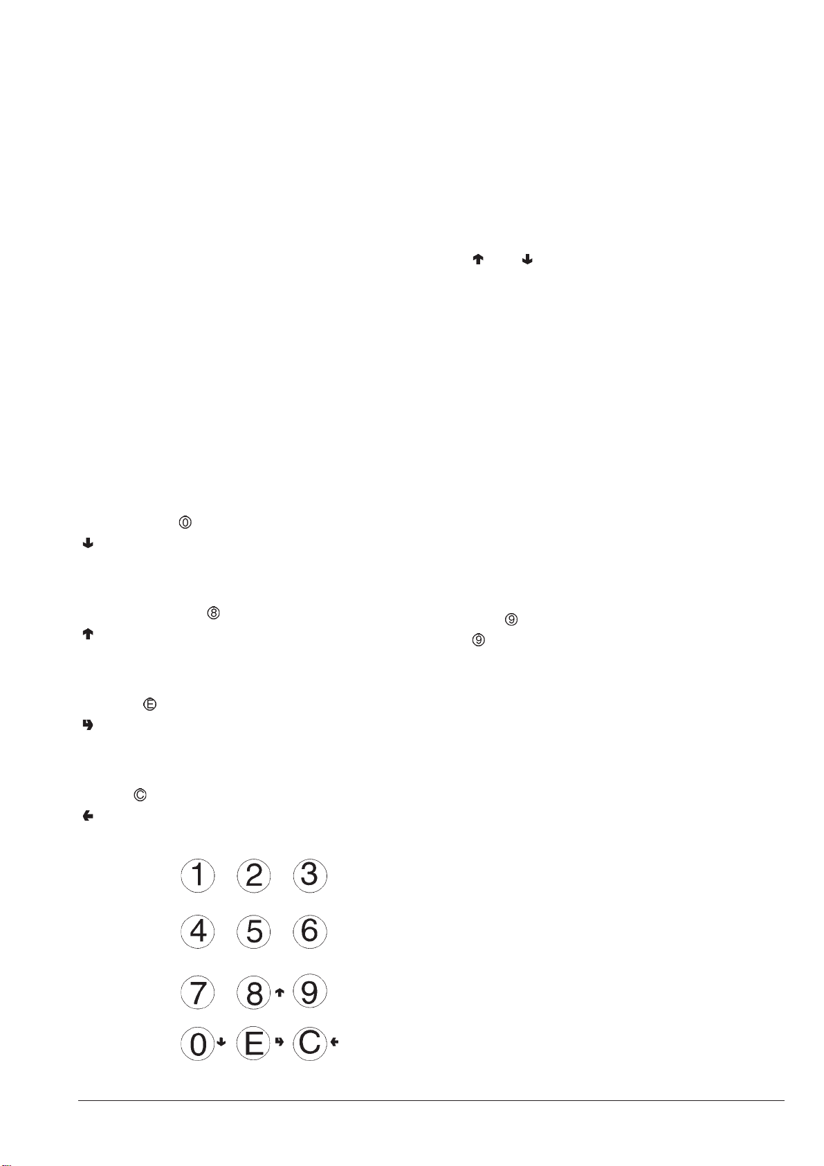
Fig. 18
OPERATING MODES
Themachinecontrolsoftwarehasthreedifferentfunction
levels, which are:
- normal operation;
- filler menu;
- technician menu.
Accordingto theoperatingmode, thedisplayand keypad
functions of the master machine change as described in
the following paragraphs.
USER INTERFACE
The interaction between system and operator happens
through the following components located on the master
machine:
- Liquid crystal display (LCD) (the number of lines and of
characters depend on the type of master).
- External keypad configured via software with numeric
keys from 0 to 9, having with the following functions in
the in the filler and technician menus:
Numeric keys
1to 7 are used toselect directly a menu itemby keying in
the corresponding number shown in the summary tables
included in the appendix to this manual.
Next menu key :
“” is used to move to the next menu option.
In the case of command management it varies the status
ofLogicalDatawhere required, or in the case of Numeric
Data it writes the value 0.
Previous menu key :
“” is used to move to the previous menu option.
In the case of command management it varies the status
ofLogicalDatawhere required, or in the case of Numeric
Data it writes the value 8.
Enter key :
“”isusedtomovefromamenutoasub-menuortoenter
a command.
InthecaseofLogicalDataitentersthestatusthatappears
on the display.
Exit key :
“” is used to move from a sub-menu to the higher level
menu, or to exit from the current command.
NORMAL OPERATING MODE
The machine is preset to normal operating mode when
connected to the power supply with the main switch on.
The lighting is switched on and the messages for the
customer are indicated on the display of the master.
FILLER MENU
The machine is preset to “filler” mode when pressing the
menuaccessbuttononthemastermachineandselecting
on which machine to operate.
The “ ” and “ ” keys scroll through the filler menu which
permits:
“Statistics” Data reading and display
“Single Prices” Changing the price for one
selection
“Special selections” Virtual selections
Return of virtual price
Two-motor selections
Photocellparameters
“Test” Test selection
Motor test
Autotest
“EVADTS” Connection
Ifamenuisnotenabledduringprogramming,atitleis
displayed in the list but it cannot be accessed.
Price key
Key is used to access directly the price/selection
combinationoftimeband0,ifthefunctionisenabledinthe
“Technician” menu.

14
© by NECTA VENDING SOLUTIONS SpA 0303 204-00
STATISTICS
Data on the machine operations is stored in both general
countersandrelativecounters,whichcanberesetwithout
losing total data.
PRINT
Connect an RS232 serial printer having a Baud rate of
9600, 8 data bit, no parity, 1 stop bit to the serial port
located on the push-button board to print all of the statis-
tics, and namely:
Total
- counter by single selection
- counter by time bands
- failure counter
- photocell errors
- motor errors
- dispensing compartment lock errors
Relative
- counter by single selection
- counter by time bands
- failure counter
- photocell errors
- motor errors
- dispensing compartment lock errors
Thehardcopyprintoutwillalsocontainthemachineinfor-
mation, and namely:
- date/time of print
- machine name
- software version
- operator code
- machine code
- Installation date.
To connect the printer, do as follows:
- press the confirm print key “ ”, displaying the mes-
sage “Confirm?”;
- connect the printer before confirming;
- press the confirm key “ ” to start printing.
DISPLAY
When pressing the confirm key “ ” the data described in
the paragraph “Printing the statistics” is sequentially dis-
played.
RESETTING THE RELATIVE STATISTICS
Statistics can be reset for relative counters globally (all
types of data) or selectively for:
- selections
- failures
- photocell errors
- motor errors
- dispensing compartment lock errors
Press the confirm key “ ”, and the message “Confirm?”
starts blinking.
Press the confirm key “ ”, the message “Working” is
displayed for a few seconds and all statistics are reset.
PRICES FOR SINGLE SELECTIONS
This function is used to change the sales price for each
selection according to the time band.
Key is used to access directly the price/selection
combination settings, if the function is enabled in the
“Technician” menu.
SPECIAL SELECTIONS
VIRTUAL SELECTIONS
Thisfunctionisusedtodefineapairofselectionsthatcan
be sold at a price different from the sum of the two
selections, using a single selection number. 10 virtual
selections can be programmed (70 to 79).
RETURN OF VIRTUAL PRICE
Thisfunctionisusedtodefine,intheeventoffailedsecond
dispensinginavirtualselection,nottocashthepriceofthe
second selection (only if an MDB payment system or
validatorareused).Withotherpaymentsystems,itcanbe
decided whether or not return the entire amount.
SELECTIONS WITH TWO MOTORS
Themachinecanbesetuptodispenselongproducts,and
dividerscanbefittedsothattwomotorsareusedforeach
single selection.
With this function the operation of two motors can be
combined,specifyingtheselectionnumberofthesecond
motor.
Thefirstmotornumberwillbetheselectionnumber,while
the selection number of the associated motor will remain
disabled.
Important notice!
After a failure to the motors of these selections, the
machineconfigurationprocedureinthe“Spiral/Selec-
tion” menu must be followed.
DISPENSING DETECTION
Thevendingmachinecanbefitted(asstandardfeatureor
as optional according to the model) with a device that, by
means of photocells, detects the passage of dispensed
products.
Thisdevice permits, in the eventof failed detection of the
dispensed product:
- set a rotation time for the spiral beyond the limit switch,
to overcome any jamming;
- return or not the paid amount;
- block further selections for the involved spiral.

15
© by NECTA VENDING SOLUTIONS SpA 0303 204-00
TEST
SELECTIONS
Thisfunctionisusedtosimulatethenormaldispensingof
products without inserting any money to check the func-
tioningofthespiralrotationbypressingtheselectionkeys.
MOTOR TEST
It activates all motors in a sequence, indicating on the
display the number of the involved selection.
AUTOTEST
A function to check, in a semiautomatic manner, the
correct operation of some devices is implemented in the
software.
Somechecksoccurautomatically,othersneedthemanual
operationofthemonitoredcomponent;presskey“ ”togo
to the next check.
The monitored devices are:
“Temperature”
The value of temperature detected by the probe is dis-
played.
Intheeventofdisconnectionthevalue-11.0isdisplayed.
In the event of a short-circuit the value 41.0 is displayed.
Press “ ” to advance.
“Buzzer”
A series of sounds is emitted.
“Compressor”
The compressor is activated/deactivated using the “ ”
and “ ” keys.
“Selections”
All selections are activated in a sequence.
“Photocells”
If the product detection device is present, the light beam
reading and interruption are checked.
“Disp compt lock”
If the device for locking the dispensing compartment
opening, use the “ ” and “ ” keys to lock and unlock the
compartmentopening.
EVADTS TRANSFER
When activating this function, the machine awaits the
connection with a device to acquire the EVADTS statis-
tics.

16
© by NECTA VENDING SOLUTIONS SpA 0303 204-00
TECHNICIAN MENU
Using the programming procedures described in this
section, it is possible to set all variables regarding ma-
chineconfiguration.
Toaccessitisnecessarytopresstheprogrammingbutton
on the master machine and enter the information for the
machine that will be set to “filler menu” mode. Press key
from the filler menu.
N.B. By pressing again the key from the technician
menu, the machine will return to “filler” mode.
The “ ” and “ ” keys scroll through the technician menu
items, which include:
Failures Read Failures
Reset failures
Motor errors
Motors status
Reset motor errors
Program parameters Cash Prices
Master/Slave
Decimal point
Bonus
Spirals/selections Configuration
Virtual selections
Return of virtual price
Two-motor selections
Product code
Photocells Spiral settling time
Money return
Empty spiral control
Disp compt lock Operating mode
Unlock time
Out of service time
Out of serv. if open
Cold parameters
Temperature
Defrosting
Cooling unit
Display Language
Personalised strings
Miscellaneous Password
Energy saving
Menu masking
Statistics Display partial
total
Cancel partial
total
Display relat. partial
total
Cancel relat. partial
total
Print relative partial
total
Cancel partial
total
Test Complete selections
Motor test
Autotest
Miscellaneous Machine info Installationdate
Machine code
Operator code
Initialising
EVADTS Pass code
Security code
Connection
Table of contents
Popular Vending Machine manuals by other brands

Automatic Products
Automatic Products SNACKSHOP 113 instruction manual

Rowe
Rowe 4900JR SERIES Field service manual

Royal Vendors
Royal Vendors TDV Helpful hints

Dixie Narco
Dixie Narco 55 Series Technical manual

BIANCHI VENDING
BIANCHI VENDING ANE23BL Installation and maintenance manual

Westomatic
Westomatic Primo Compact Cleaning manual


Intelligent Vending
Intelligent Vending MULTI-6 installation instructions

Jofemar
Jofemar Vision Easy Combo Hardware installation and maintenance guide

Multiplex
Multiplex FreshBlender FAQ & Troubleshooting

Westomatic
Westomatic EVOLVE FITTING PLINTHS

Necta Vending Solutions SpA
Necta Vending Solutions SpA Sfera Installation, use and maintenance manual

Jofemar
Jofemar Vision ES-PLUS Technical manual