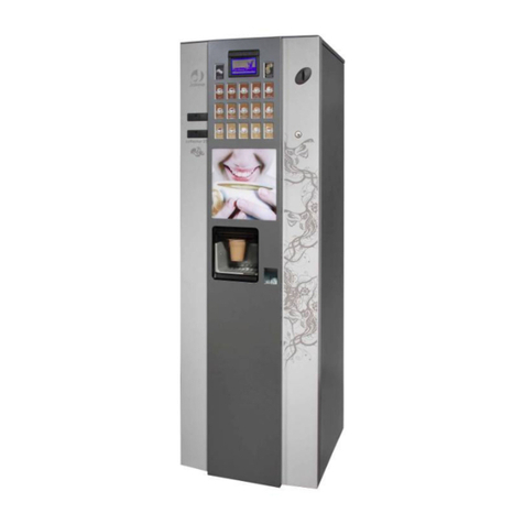
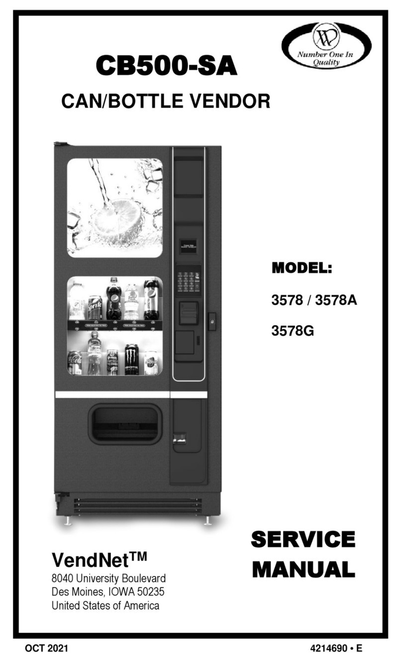
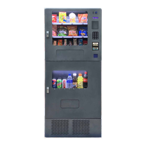
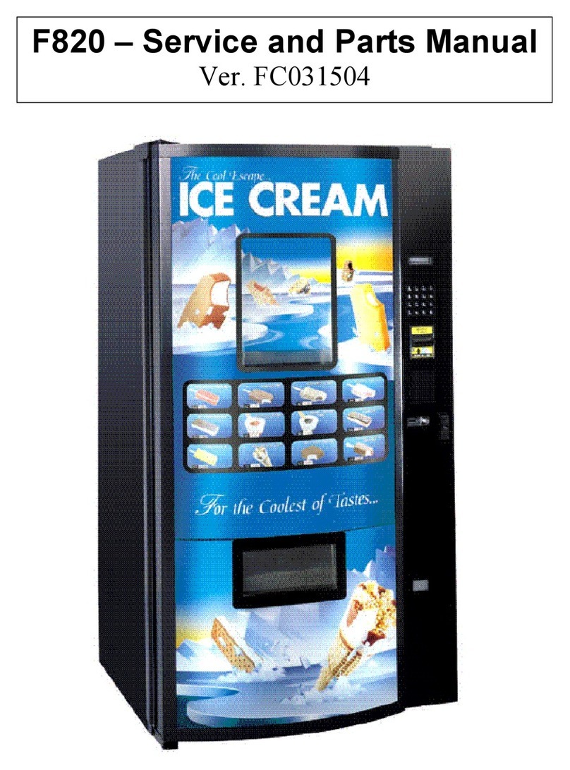
Jofemar COFFEEMAR G-500 V2 User manual

MNP37M03GBV00 Date: 24-11 Rev. 0
Page 1of 79
INGLÉS
COFFEEMAR G-500 V2
USER’S MANUAL

MNP37M03GBV00 Date: 24-11 Rev. 0
Page 2of 79
F WARNINGWARNING
Read the following instructions carefully before installing the machine:
-Take the machine down from the pallet before opening it.
-ii Before connecting to mains, make sure that the power supply characteristics
coincide with those of the machine.
-Do not clean the machine with concentrated products as they may attack the paint
and alter the colour.
-The machine should be installed in a vertical position, with a maximum back to
front or lateral tilt of 5% (~2 °).
-If the power cable is damaged, it should be replaced by the manufacturer or after
sales service or similar qualified personnel to prevent hazards.
-The power cable plug should be installed so the machine can be easily
disconnected from mains.
-Working temperature between 5 °C and 40 °C.
-Protect the machine against humidity, dust, dirt, etc.
-Frequent washing can prevent breakdowns and extend the machine’s life.
This machine has been designed and built in full compliance with current safety and
environmental regulations.
This manual is an integral part of the machine and should always be available
inside the machine for consultation until it is finally disassembled or taken apart.
The following should be taken into account before the machine is installed:
-Work inside the machine should only be carried out by competent personnel
with the necessary skills, it being the buyer’s responsibility to comply with this
provision.
-In spite of these safety measures, personnel associated with the machine
should be aware of the hazards involved when manipulating the machine.
-Should this manual be lost or damaged, you can obtain a new copy by
notifying the manufacturer, mentioning the machine ID and the data which appears
on the machine ID label.
-The kind of technical problems which may occur are usually easy to solve if
you follow the instructions in this manual. Should this not be possible, you should
contact technical support service, in which case you should indicate the information
on the machine ID label.

MNP37M03GBV00 Date: 24-11 Rev. 0
Page 3of 79
Jofemar Catalunya
C/Cristóbal de Moura, 191-193.08019 BARCELONA.SPAIN
Tel. +34 93 266 24 66. Fax. +34 93 307 89 02
Jofemar Levante
Pol. Ind. Alquería de Raga. C/Faitanar, 16. 46210 PICANYA. Valencia SPAIN.
Tel. +34 96 159 33 15. Fax. +34 96 159 19 56
Jofemar Madrid
Pol. Ind. Casablanca. C/Doctor Severo Ochoa, 35, local 5f. 28100 ALCOBENDAS.
Madrid SPAIN Tel. +34 91 662 27 99. Fax. +34 91 661 48 11
Jofemar Sevilla
Pol. Ind. Pisa. C/ Juventud , 24. Edificio Juventud. 41927 MAIRENA DEL JARAFE.
Sevilla SPAIN Tel. +34 95 418 47 34. Fax. +34 95 418 16 67
Jofemar Deutschland
Willicher Damm 119. Airport-Park. 41066 MÖNCHENGLADBACH –GERMANY.
Tel. +49 (0) 2162 477670. Fax.+49 (0) 2161 4776716
Jofemar USA
Jofemar Conneticut. 470 West Ave. Suite 1008 STAMFORD, CT 06902. USA.
Tel. +1 203 406 1234. Fax. +1 203 328
Jofemar France
13 Rue des Ateliers, 91350 Grigny, France.
Tel. +33 169451965. Fax. +33169451398
Jofemar S.A.
Ctra. de Marcilla Km.2, 31350 Peralta. Navarra, SPAIN
http://www.jofemar.com Tel. +34 948 75 12 12. Fax. +34 948 75 04 20

MNP37M03GBV00 Date: 24-11 Rev. 0
Page 4of 79
Table of Contents
1.-Symbols used in this document................................................................................6
2.-Description of the machine.......................................................................................7
2.1.-Construction......................................................................................................8
2.1.1.-Advertising panels.....................................................................................8
3.-Technical specifications. ..........................................................................................9
3.1.-Initial electrical installation.................................................................................9
4. -Installation and start up...........................................................................................9
4.1. –Installation.......................................................................................................9
4.2. -Start up..........................................................................................................10
4.2.1. -Connection to water mains. ....................................................................11
4.2.2.-Connection to mains................................................................................12
4.2.3.-Safety switch...........................................................................................13
5.-Preliminary operations............................................................................................14
5.1.-Cup loading.....................................................................................................14
5.2.-Spoon loading.................................................................................................15
5.3. -Filling the water circuit....................................................................................16
5.4.-Disinfection and washing of beaters and water circuits....................................18
5.5.-Loading sugar, soluble products and coffee beans..........................................22
6. -Basic machine operation concepts........................................................................23
6.1. -Safety systems. .............................................................................................23
6.2. -Water circuit...................................................................................................24
6.3. -Electrical drawings.........................................................................................26
6.4. -Air-break.......................................................................................................28
6.5. -Pressure boiler...............................................................................................29
6.6.-Coffee mil –doser assembly...........................................................................31
6.7.-Coffee brewing assembly................................................................................32
6.8.-Soluble container assembly and beater assembly...........................................35
6.9. -Cup dispensing assembly..............................................................................36
6.10.-Sugar and stir-stick dispensing assembly......................................................39
6.11. -Rotating arm................................................................................................40
6.12. -Kits available as an option............................................................................41
6.12.1. -Water intake pump................................................................................41
6.12.2.-Water softener.......................................................................................43
6.12.3 Flavour filter for hot drinks .......................................................................48
6.12.4 Jofemar BT-10 banknote reader kit..........................................................49
6.12.5 Coffeemar Modem Kit..............................................................................51
7.-Machine cleaning and maintenance. ......................................................................53
7.1.-Daily cleaning. ................................................................................................54
7.2.-Weekly cleaning..............................................................................................55
7.3.-Monthly cleaning.............................................................................................56
7.4.-Yearly cleaning...............................................................................................56
8. -Version names......................................................................................................56
8.1. -Coffeemar G-500 with 3 beaters and 4 containers. ........................................56
9.-Compliance with regulations...................................................................................57
10.-Products which can be dispensed from the machine............................................58
11. -Programming mode.............................................................................................58
11.1. -Programming options...................................................................................58
11.1.0. –OP_0 price options. ..............................................................................61
11.1.1 OP_1 money accounting. (only MDB machines)......................................62
11.1.2 –OP_2. product accounting......................................................................62
MNP37M03GBV00 Date: 24-11 Rev. 0
Page 5of 79
11.1.3. –OP_3 machine configuration.................................................................63
11.1.4. -OP_4 General inhibitions. (Coin inhibition)............................................66
11.1.5. -OP_5 Clock programming....................................................................66
11.1.6. -OP_7 Product codes.............................................................................66
11.1.7. -OP_18 Machine program version. .......................................................67
11.1.8. -OP_19 Level code programming. .........................................................67
11.1.9. -OP_20 Fault review..............................................................................67
11.1.10. -OP_21 Resetting faults......................................................................67
11.1.11. -OP_22 Machine manual operation......................................................68
11.1.12. -OP_23 Programming products in the machine....................................68
11.1.13. -OP_31 Programming the machine via a PC........................................68
11.1.14. -OP_32 Machine maintenance.............................................................69
11.1.16. -OP_33 Coffee maker configuration.....................................................70
11.1.17. –OP_34 Programming product dose.....................................................70
11.1.18. -OP_35 Production reset......................................................................72
11.1.19. -OP_40 Coin reloading and accounting in change tubes (MDB)...........72
11.1.20. -OP_41 Discharging change tubes (MDB) ...........................................72
12. -Troubleshooting.........................................................................................72

MNP37M03GBV00 Date: 24-11 Rev. 0
Page 6of 79
1.-Symbols used in this document
ii This symbol means there are more detailed explanations on this subject elsewhere in
the manual.
èThis symbol means that the text in question refers to programming.
FThis symbol indicates very important information.
~This symbol is a warning of high voltage hazard.

MNP37M03GBV00 Date: 24-11 Rev. 0
Page 7of 79
2.-Description of the machine
4
3
8
27
9
6
1
5
1. Cabinet assembly 12. Rotating arm
2. Door 13. Product delivery recess wall
3. Programming button 14. Steam exhaust
4. Door open safety switch 15. Sugar container
5. Compact 16. Stir-stick slide
6. Vault 17. Cup storage tube assembly
7. Control card assembly 18. Cup dispenser
8. Espresso and air-break assembly 19. Cup collector
9. Soluble assembly 20. Waste collection funnel
10. Coffee bean container 21. Waste bin
11. Soluble container 22. Coffee grounds collection funnel

MNP37M03GBV00 Date: 24-11 Rev. 0
Page 8of 79
2.1.-Construction
The metal parts are constructed in 1-mm thick steel, with rustproof protection and
an external coat of paint. The advertising panel is made of PET.
The user selection and information keys are located on the outside of the door. The
programming button, located inside the door, allows you to access the various functions
available in the machine.
Figure 2.02 shows the main parts of the machine which make up the front part as
well as maximum dimensions.
figure 2.02
1. Product selection
pushbuttons
2. Coin slot
3. Sugar level pushbutton
4. Alpha-numerical display
5. Credit return pushbutton
6. Machine opening key hole
7. Coin return recess
8. Product delivery
9. Protective door
10. Cup with product
11. Top advertising panel
12. Door advertising panel
13. Bottom cabinet cover
2.1.1.-Advertising panels.
The machine has two advertising panels with the following dimensions:
Width Height Thickness
Door panel 562.5 1093.5 3
Top panel 563 213.5 3
The advertising panels are backlit with one or more fluorescent tubes.
Coffeemar
10
9
3
1118
4
12
7
8
11
5
6
2
1
600
1825
603
Jofemar
13

MNP37M03GBV00 Date: 24-11 Rev. 0
Page 9of 79
To change the door advertising panel, remove the ten screws that hold the product
delivery trim to the door. To access these screws you will need to disassemble the cup
retrieval funnel guide and the transparent protective door. You will also need to remove
the right-hand vertical profile which holds the panel when you open the pushbutton
panel.
Once the panel has been removed, replace it with the new panel and follow the
same process in reverse order, replacing the side profile, product delivery trim, the
protective door and the funnel guide.
3.-Technical specifications.
•~Supply voltage........................220 ± 10%VAC
•Supply frequency...................................50 –60 Hz
•Power consumption.................................. 1100 W
•Water mains pressure .........................0.5 –10 bar
•Water circuit pressure (boiler).......................12 bar
•Boiler power consumption......................... 1000 W
•Boiler capacity.............................................370 cc
•Height......................................................1825 mm
•Width.........................................................600 mm
•Depth........................................................603 mm
•Weight........................................................147 kg
3.1.-Initial electrical installation.
~Prepare a 220 ± 10%VAC, 50-60Hz and 10A socket protected with an automatic
connection system. The socket should match the machine plug (European with ground
connection). Follow all Low Voltage Installation Regulations and check that ground
connection works properly once the machine has been installed.
4. -Installation and start up.
4.1. –Installation
Installation and maintenance operations should only be carried out by
qualified technical personnel.
The machine can be transported to the place where it is to be installed using a fork-
lift truck, inserting the fork under the front of the machine. In order for the machine to be
properly installed, use the adjustable legs provided in a bag inside the machine. Screw
the legs onto the four threaded fixtures located at the bottom of the machine.
ii

MNP37M03GBV00 Date: 24-11 Rev. 0
Page 10 of 79
The machine should not be installed out of doors and should be in a dry
environment with temperatures never below 0 °C with a maximum temperature of 32 °C
and humidity under 70%. Do not install in excessively humid locations or in places
where a water jet is used for washing (such as large kitchens).
WARNING: in view of the sensitivity to humidity and temperature of some products
the abovementioned conditions need to be met.
.
FIMPORTANT :It is important for the machine to be level, as it should operate
in a vertical position, both laterally and back to front, with a maximum inclination of 2°
(5%).
4.2. -Start up.
Once you have installed the machine in place, cover the front bottom part of the
machine (where you inserted the forklift truck’s fork) using a piece which is located
inside the machine. Open the door and anchor the cover on the three screws located on
the legs.
Insert the product and price labels. To do this, open the pushbutton panel, removing
the butterfly screws. The machine should look as shown on fig. 4.01
figure 4.01
1. Product label slot
2. Space for the price label
3. Custom LCD display control card. Contrast is controlled by means of a variable
resistance
4. Programming button
2
13
4

MNP37M03GBV00 Date: 24-11 Rev. 0
Page 11 of 79
The price labels are fluorescent segments. To show
the desired price, shade in excess segments. The back
side of the label is black, so it can be inserted facing the
other way if you do not wish to indicate a price. There are
two types of labels, as shown on the figure.
Insert each product label in its respective key
through slot 1 and the price label in recess 2, as shown
in the figure.
The product labels should be no more than 0.3 mm
thick.
4.2.1. -Connection to water mains.
Before connecting the machine to water mains, please take into account the
following requirements for the water supply:
-Please ensure water is drinkable by obtaining relevant certificates from a testing
laboratory.
-Make sure water mains pressure is between 0.5 and 10 bar. With pressures under
0.5 bar it will be necessary to install a pump. if the water mains pressure is above
10 bar, you will need to install a 3-bar pressure reducer in the machine’s water
supply hose. In any case, it is always advisable to install a pressure reducer if the
water supply pressure is likely to experience significant variation.
-Make sure there are no impurities in the water. If the water is very hard (above 20 º
FF) it is advisable to install a water softener (available as an option), or a resin or
ion exchange water softener with a capacity that is appropriate for the machine’s
water consumption. The water softener should be periodically regenerated
according to the manufacturer’s instructions.
It is advisable to install a stopcock in the water supply, outside the machine,
in an easily accessible location.
After the above requirements have been met, connect the machine water supply
solenoid valve 3/4” connection to water mains, using a hose with a minimum internal
diameter of 6mm, appropriate for withstanding the water mains pressure and
appropriate for food use (figure 4.02.1).
figure 4.02.1
1. ¾” gas water inlet solenoid valve
2. ¾” female quick plug
3. Water supply silicone hose
3
12

MNP37M03GBV00 Date: 24-11 Rev. 0
Page 12 of 79
4.2.2.-Connection to mains.
~The machine is set up to work with a single-phase voltage of 230 V, 50 Hz.,
protected with 10 A and 16 A fuses.
Before connecting the machine to mains, please make sure that mains voltage
coincides with the data which appear on the machine ID label (which is affixed to the
inside of the machine door) with variations under ±6%.
-The supply line should be appropriate for the distributor’s usage needs.
-Use a ground leakage protection system.
-Position the machine so the mains socket is accessible.
The mains socket should be compatible with the machine’s plug. If it is not, it should
be replaced with a compatible socket.
The connection should include a grounding connection in compliance with
regulations.
FIt is very important that the electrical circuit has an appropriate ground
connection which meets current regulations. If in doubt, have a qualified
technician check the installation.
The machine is supplied with a power supply cable, type H05VV-F 3x1,5 mm²
with a SCHUKO plug.
Do not use adapters, extension cords or multiple socket devices.
Before powering the machine, make sure that you have connected the machine to
water mains and that the stopcock is open.
Jofemar S. A. does not assume any liability should the above instructions not be
headed in whole or in part.

MNP37M03GBV00 Date: 24-11 Rev. 0
Page 13 of 79
ii Should the power supply cable be damaged, it should be replaced by qualified
personnel to prevent hazards.
To replace the power supply cable, follow the instructions below:
-Remove the control card protection lid.
-Disconnect power supply cable phase and neutral wires connected to the filter,
as well as the ground connection.
-Use a no. 7 socket wrench to remove the nut that holds the power supply cable
host.
-Remove the wiring hole gasket using an appropriate tool and remove the power
supply cable.
Install the new power supply cable (H05VV-F 3x1,5 mm², with SCHUKO plug) following
the steps described above in reverse.
4.2.3.-Safety switch.
The machine is equipped with a general safety microswitch which cuts off power
supply to all electrical and electronic components when the door is opened.
If you need to do live work on the machine with the door open you will need to close
the safety switch manually. To do this, pull the switch button (figure 4.03).
FAny live operation carried out with the power on and the door open (except
for washing operations) should be carried out by authorised personnel with
appropriate technical skills and duly informed about the hazards involved.
3
5
9
12
4
1
6
8
7
figure 4.03
1. Door switch
2. Main switch
3. 16 A fuse
4. 10 A fuse
5. RS-232 interface output
6. Compact-control card
connection
7. Connection to executive
compact
8. External coin return motor
connection
9. Compact

MNP37M03GBV00 Date: 24-11 Rev. 0
Page 14 of 79
5.-Preliminary operations.
In order for the machine to be fully operational, several preliminary operations are
necessary.
5.1.-Cup loading.
Only cups specifically designed for automatic drink dispensing machines should be
used. The cups should not be transparent or made in a photo-absorbent colour. This
machine is equipped to deliver cups of different sizes. These are classified in terms of
their diameter measured just under the top ring. The cups are classified into:
•Cups with a diameter under top ring between 65 and 67 mm
•Cups with a diameter under top ring between 67 and 69 mm
Diameter
Minimumheigth=2mm
The distance between the rims of two adjacent cups in a pile should be at least
2mm.
When you load cups for the first time (all storage tubes are empty) proceed as
follows:
-check that the cup storage tube closest to the cup dispenser hole is centred
above this hole.
-remove the lid of the cup storage tube assembly
-insert the cups in all tubes except for the tube immediately above the cup
dispenser hole.
-if there are now cups present when the power is turned on, this will be detected
by the machine and it will rotate the tube assembly until it finds a tube with cups.
-fill the empty tube with cups.
-press the button located on the cup dispenser to manually drop cups, one by
one, until a cup reaches the product filling position.
-put the cover back on the cup storage tube assembly.
When the machine is turned on, if it does not find any cups in the current tube,
the dispenser will rotate the cup storage tube assembly to the next position. If
no cups are detected, it will repeat this process eight times or until it detects a
cup. If no cups are detected in any tube, the message “cups missing” will
appear on the display and the machine will be left out of service.

MNP37M03GBV00 Date: 24-11 Rev. 0
Page 15 of 79
5
3
2
1
6
4
7
figure 5.01
1. Cup storage tube assembly
2. Cup storage tube assy. lid
3. Cup dispenser
4. Manual cup dispensing button
5. Cup collector
6. Spoon dispenser
7. Spoon storage slide
5.2.-Spoon loading.
Only spoons designed to be used in automatic dispensing machines should be
used.
Spoon thickness should be between 1.25 mm and 1.75 mm and spoon length
between 75 mm and 91 mm.
The classification of spoons depends on their lengths (see fig. 5.02):
1. Position “A” on the figure. This adjuster position allows you to deliver spoons
with lengths between 75 and 91 mm
2. Position “B” on the figure. This adjuster position allows you to deliver spoons
with lengths between 91 and 99 mm
3. Position “C” on the figure. This adjuster position allows you to deliver spoons
with lengths between 99 and 107 mm
Spoon channel without adjuster. This allows you to deliver spoons with lengths
between 107 and 115 mm
To load spoons follow the procedure below (refer to figure 5.02):
-remove the spoon storage slide counterweight.
-insert a spoon bundle, held together with a ribbon in the slide.
-hold the spoon bundle with one hand while you cut the lower part and pull the
ribbon upwards.
-load more spoon bundles following the same procedure until the storage slide is
full.
-replace the counterweight on the spoons.
FMake sure you avoid using bent or curved spoons, spoons with flash. Also
ensure no spoons are left in a horizontal position.

MNP37M03GBV00 Date: 24-11 Rev. 0
Page 16 of 79
4
A C
3
B
5
3
Tirar de la cinta
Cortar la cinta
2
7
1
8
6
5
4
Detail "A"
Detail "A"
SPOON LENGTH
ADJUSTER POSITION
figure 5.02
1. Spoon dispenser
2. Spoon placer
3. Spoon storage slide
4. Spoon channel supplement
5. Spoon length adjuster
6. Counterweight
7. Spoon bundle
8. Spoon bundle ribbon
5.3. -Filling the water circuit.
Make sure the machine water supply stopcock is in the open position.
Place the waste bin on the guide located at the bottom of the machine. Place the
waste level sensor floater which hangs from a chain connected to the waste level
sensor switch inside the bin.
Check that the air-break manual emptying silicone tube shutter is applying pressure
on the silicone tube to ensure that the water does not go directly into the waste bin
(fig. 5.03.1).
1
2
3
Figure 5.03.1
1. Air-break
2. Air-break drain tube
3. Shutter

MNP37M03GBV00 Date: 24-11 Rev. 0
Page 17 of 79
Connect the electrical circuit power supply cable to the mains switch and close the
door of the machine so it is turned on.
The machine will automatically carry out an internal check. It will first move the
rotating arm to ensure it is working properly and then leave it in standby position. The
coffee assembly cam position is also checked and if it is not in place, acting on the
relevant micro switch, the cam will move until it is in the correct position to begin the
assembly’s operating cycle. (figure 5.03.2)
It will then check whether there is water in the air-break. Since it is empty, it will
open the water intake solenoid valve and filling will begin. Once the air-break has been
filled, water will begin to pass through the air-break into the pressure boiler, through a
pump located between them. While the boiler is filling up, several things take place:
water continues to go into the air-break because a micro-switch detects that the water
level is coming down. At the same time, a solenoid valve in the boiler opens to prevent
excess pressure in the boiler. Thus, when the boiler is full, water will begin to come out
through the solenoid valve. The valve will remain open for a few seconds so the boiler is
filled correctly.
FImportant: If after this operation water does not come out through the soluble
beaters, this means the pressure boiler has not filled up completely, so it will be
necessary to carry out a manual washing of the machine until water comes out of
the beaters.
Thus, what can mainly be observed is that the solenoid valve that lets water into
the air-break will open as often as necessary, until the air-break control system detects
that the water circuit has reached the required stand-by level.
FThe machine will be left out of service if after 10 minutes the air-break has
not filled up. This may be because the stopcock is not open or because the
emptying tube shutter is not closed and the water is going directly into the waste
bin.
Once this level has been reached, the boiler heating element will begin to heat the
water until it reaches working temperature.

MNP37M03GBV00 Date: 24-11 Rev. 0
Page 18 of 79
18
20
21
17
19
6
7
5
15
4
3
11
9
22
10
1
2
8
14
12
13
16
figure 5.03.2
1. Inlet solenoid valve or pump vibration
2. Air-break filling tube
3. Air-break
4. Air-break filling control system
5. Tube from air-break to volume
counter
6. Volume counter
7. Tube from volume counter to
pressure pump
8. Pressure pump
9. Pressure boiler filling tube
10. Safety valve water outlet
11. One-way valve
12. Safety valve (set at 12bar)
13. Pressure boiler
14. Product dispensing solenoid valves
15. Espresso coffee brewing assembly
16. Soluble mixer assembly
17. Air-break emptying tube
18. Air-break overflow tube
19. Brewing assembly drain tubes
20. Waste bin full safety system
21. Waste bin
22. Water feed tank (optional)
5.4.-Disinfection and washing of beaters and water circuits.
Before the machine is put into operation, the coffee assembly and beaters which
mix the products and the water circuits need to be cleaned to ensure the product is sold
in the most hygienic conditions.
The water circuit should be cleaned to get rid of any dirt in the water circuit or the
boiler. The following steps should be follower for manual washing:
•Press the machine programming button, which is located inside the door,
behind the cup storage tubes, and then press the manual cup dispensing
button, located on the cup dispenser assembly. To repeat the washing
operation just press this button again.
You then need to ensure that any parts which come into contact with foodstuffs
when the soluble and water are mixed together with the beaters are clean and that any
water used in washing out the water circuit does not remain on the beaters. To do this,
you have to individually clean and disinfect each part. Follow the process outlined
below:
-Remove the soluble product containers which are located in the beater assembly
(figure 5.04.1) and place in a clean, disinfected place.

MNP37M03GBV00 Date: 24-11 Rev. 0
Page 19 of 79
figure 5.04.1
press the container towards the inside of the cabinet
and, once the tabs are free, pull upwards and
forwards. Follow the same procedure with the
remaining containers.
-Remove the beater and the beater exhaust funnel lid. To do this, grab both parts
and pull upwards until they come out of the beater funnel. then pull outwards until
they are free (figure 5.04.2).
1
2
figure 5.04.2
1. Beater exhaust funnel
2. Beater exhaust funnel lid
-Loosen the silicone tube from its connection to the beater funnel and the product
dispensing silicone tube. Disassemble the beater funnel, beater elbow and the
connection between the tube and beater funnel assembly. To do this, rotate the
parts until the tabs of the beater elbow come loose from the elbow support and
pull outwards.
3
2
1
figure 5.04.3
1. Beater funnel
2. Beater elbow
3. Tube to beater funnel connection

MNP37M03GBV00 Date: 24-11 Rev. 0
Page 20 of 79
Disassemble the beater paddle pulling it out of the motor shaft. This part is
anchored to the beater motor with a flange. Then, remove the three screws that hold the
beater elbow support to the plate and remove the support, the beater retainer and the
beater retainer support. Loosen the beater spinner, which is anchored to the motor shaft
with a flange (figure 5.04.4).
1
5
4
32
figure 5.04.4
1. Beater paddle
2. Beater elbow support
3. Beater retainer
4. Beater retainer support
5. Spinner
Follow the same procedure for each of the beaters on the machine.
Prepare an appropriate container with a basic solution of chlorine-based detergents,
which can be found in shops which sell pharmaceutical products.
To disinfect the parts of the beater and product containers, submerge them in the
prepared solution for about 20 minutes. To clean them effectively you may need to
use a brush or similar implements.
After disinfection, dry the parts carefully with compressed air, a dryer or disinfected
cloths. Then reassemble the parts following the above steps in the reverse order.
Replace the soluble product containers.
Remove the espresso coffee brewing assembly following the steps detailed below:
-Remove the assembly attachment piston (no. 1fig. 5.04.5) by turning it
counter-clockwise. After unscrewing it from the thread that joins it to the lid,
remove the assembly until the three guiding rods come out of their holes.
-After removing the brewing assembly, remove the assembly nozzle (no. 2fig.
5.04.5), the silicon tube connecting to the nozzle located in the rotating arm
(no. 3fig. 5.04.5).
-Remove the Teflon tube used to bring water under pressure from the water
boiler. To do this, just unscrew the brass nut that connects this tube to the
brewing assembly (no. 4fig. 5.04.5).
Table of contents
Other Jofemar Vending Machine manuals

Jofemar
Jofemar Coffeemar G-250 User manual

Jofemar
Jofemar Vision Easy Combo Operating manual

Jofemar
Jofemar Coffeemar G-250 Product manual

Jofemar
Jofemar Vision ES-PLUS User manual

Jofemar
Jofemar TAOS Series User manual

Jofemar
Jofemar vision multiseller Product manual

Jofemar
Jofemar Vision Snack Plus User manual
Popular Vending Machine manuals by other brands

Everest
Everest VX Operator's manual

BIANCHI VENDING
BIANCHI VENDING ANE23BL Installation and maintenance manual

Anvil
Anvil POPCORN MACHINE 8oz Installation, Operation and Care Manual

Wittenborg
Wittenborg 9100 Cleaning guide

Douwe Egberts
Douwe Egberts Cafitesse 4000 operating instructions

Sielaff
Sielaff SU 1500 EC02 Series Original operating instructions