manuals.online logo
Brands
  1. Home
  2. •
  3. Brands
  4. •
  5. OCEE DESIGN
  6. •
  7. Office Equipment
  8. •
  9. OCEE DESIGN DEN.Curve User manual

OCEE DESIGN DEN.Curve User manual

Assembly Instructions
DEN.Curve
1 Person
SASS-0065 A
850w Side Panel
A x1 2-way Junction
Bottom Connector Link
B x1
Z x3
Den.Curve Worksurface
E x1 M6x20 Button Head Bolts
W x10
Shell Components
Worksurface Components
Tools
4mm Allen Key/Phillips Screwdriver Cushioned Mallet 13mm Spanner
YSmall Worksurface Fixing Bracket x5
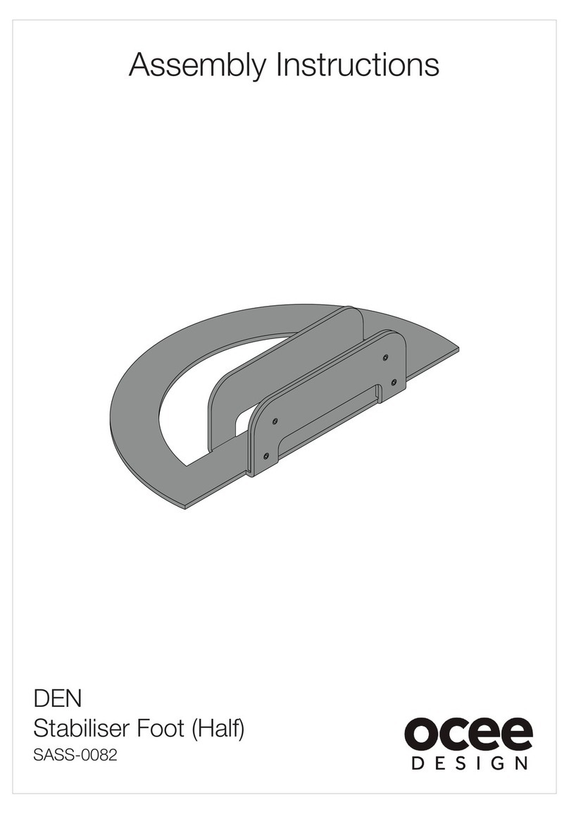
Stabiliser Foot (Half)
U
DEN.Curve Assembly Instructions DWG No: SASS-0065
Revision: A (27/10/15)
Drawn by: JB
Drawn date: 13/07/15
650w Back Panel
C x1
See SASS-0082 For Assembly
Curved Panel
D x1
A
850w Side Panel
C
650w Back Panel
Z
Bottom Connector
Link x3
Y
Small Worksurface
Fixing Bracket
E
Den.Curve Worksurface
D
Curved Panel
B
2-Way Junction
(90°)
U
Half Staibiliser Foot
see SASS-0082
A
U
D
C
B
E
Y
Y
Y
Y
Assembled Configuration Illustration (for Reference)
DEN.Curve Assembly Instructions DWG No: SASS-0065
Revision: A (27/10/15)
Drawn by: JB
Drawn date: 13/07/15
IMP RTANT: These assembly instructions use a LEFT HAND unit for illustration. To build a RIGHT HAND unit, please mirror the proceeding steps.
1.
For assembling the half stabiliser foot (U) please follow SASS-0082 instructions and
attach to the 850w side panel (A).
Insert the modular screws in the 850w side panel (A) into the keyholes in the 2-way
junction (B), making sure that all of the screws have engaged into the keyholes.
2.
After making sure all of the screws are engaged in the keyholes, tap the top of the
850w side panel (A) with a cushioned mallet to fully engage.Tie the 850w side panel
(A) to the 2-way junction (B) using a bottom connector link (Z). Insert this over one of
the levellers (between the nut and the bottom of the panel/junction) in the hooked slot
and pivot around to insert the other leveller into the straight slot. Fully tighten both
nuts using a 13mm spanner to trap the connector (Z).
3.
Insert the modular screws in the 650w back panel (C) into the keyholes in the 2-way
junction (B), making sure that all of the screws have engaged into the keyholes. (see
step 1 for method).
4.
Tap the top of the 650w back panel (C) with a cushioned mallet to fully engage.
Tie the 650w back panel (C) to the 2-way junction (B) using a bottom connector link
(Z). (see step 2 for method).
Panel
Connector
M8 nut
Leveller
Junction
Z
Bottom Connector Link
B
2-Way Junction
A
850w Side Panel
DEN.Curve Assembly Instructions DWG No: SASS-0065
Revision: A (27/10/15)
Drawn by: JB
Drawn date: 13/07/15
U
Half Stabiliser Foot
see SASS-0082
for assembly
C
650w Back Panel
Z
Bottom Connector Link
5.
Insert the modular screws in the 650w back panel (C) into the keyholes in the curved
panel (D), making sure that all of the screws have engaged into the keyholes. (see
step 1 for method).
6.
Tap the top of the 650w back panel (C) with a cushioned mallet to fully engage.
Tie the 650w back panel (C) to the curved panel (D) using a bottom connector link (Z).
(see step 2 for method).
100
100
25
25
462.50
7.
Attach the worksurface fixing brackets (Y) to the Den structure using 1x M6x20mm
socket button head machine screw (W) per bracket (Y) in the positions shown above.
Use the top holes for a 730mm worksurface height and the bottom holes for a
750mm worksurface height (see above). When fixing the brackets to the structure,
make sure to pass the machine screws through the 7mm hole and not the slot.
100
100
25
25
462.50
8.
Lower the worksurface (E) onto the brackets attached to the structure in step 7.
Attach the worksurface fixing brackets (Y) to the underside of the worksurface (E)
using 1xM6x20mm socket button head machine screw (W) per bracket (Y).
DEN.Curve Assembly Instructions DWG No: SASS-0065
Revision: A (27/10/15)
Drawn by: JB
Drawn date: 13/07/15
D
Curved Panel
Z
Bottom Connector
Link
W
M6x20 Button
Head Bolts
(x5)
7mm
hole
Y
Small Worksurface
Fixing Bracket
(x5)
750mm Worksurface height
Y
730mm Worksurface height
W
M6x20 Button
Head Bolts
(x5)
9.
When the Den unit is in its final position, re-adjust the levellers as necessary to ensure
the unit is balanced. If adjusting levellers with a bottom connector link (Z) attached,
make sure the nut is fully tightened up to the link (Z) after adjustment of the leveller
height.
DEN.Curve Assembly Instructions DWG No: SASS-0065
Revision: A (27/10/15)
Drawn by: JB
Drawn date: 13/07/15

Other OCEE DESIGN Office Equipment manuals

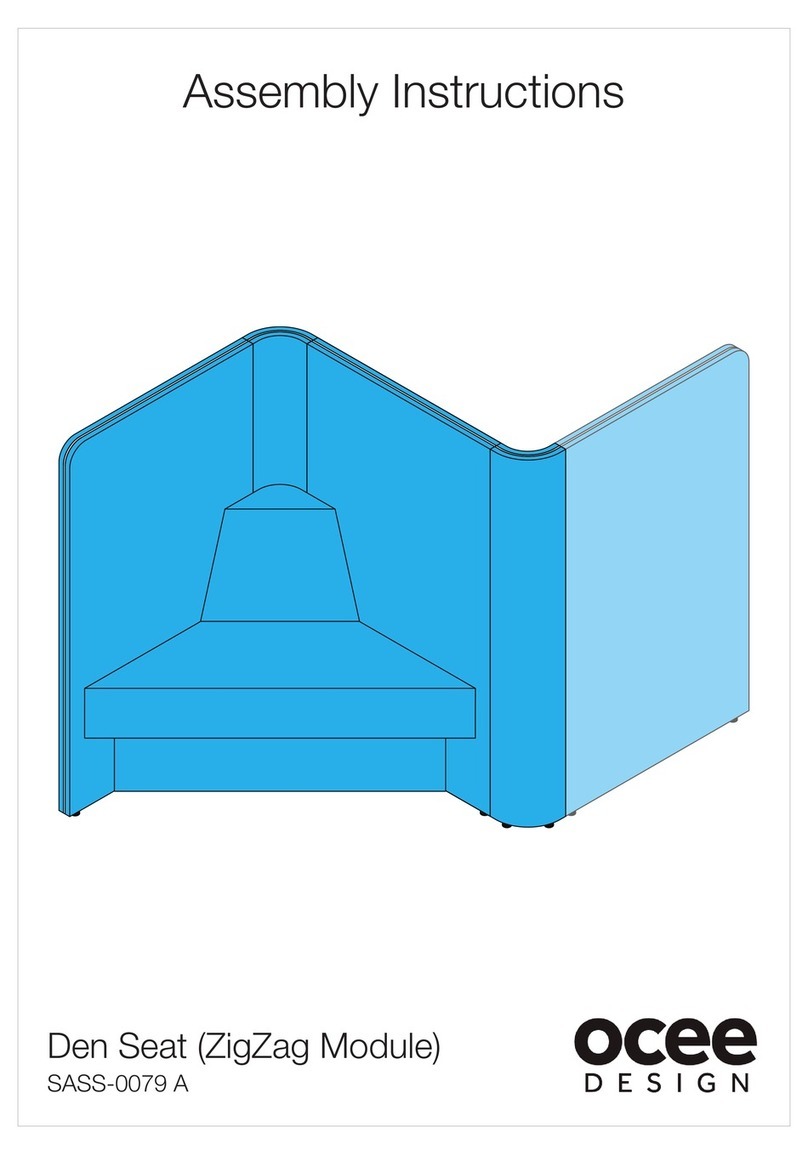
OCEE DESIGN Den Seat SASS-0079 A User manual

OCEE DESIGN

OCEE DESIGN Den Seat SASS-0079 A User manual

OCEE DESIGN DEN.Panel Triple SASS-0068 A User manual

OCEE DESIGN

OCEE DESIGN DEN.Panel Triple SASS-0068 A User manual

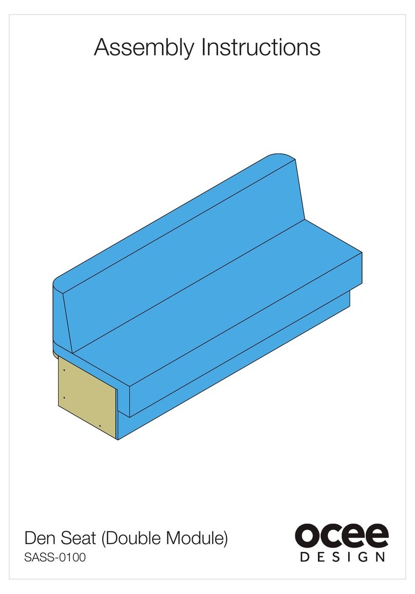
OCEE DESIGN SASS-0100 User manual

OCEE DESIGN

OCEE DESIGN SASS-0100 User manual

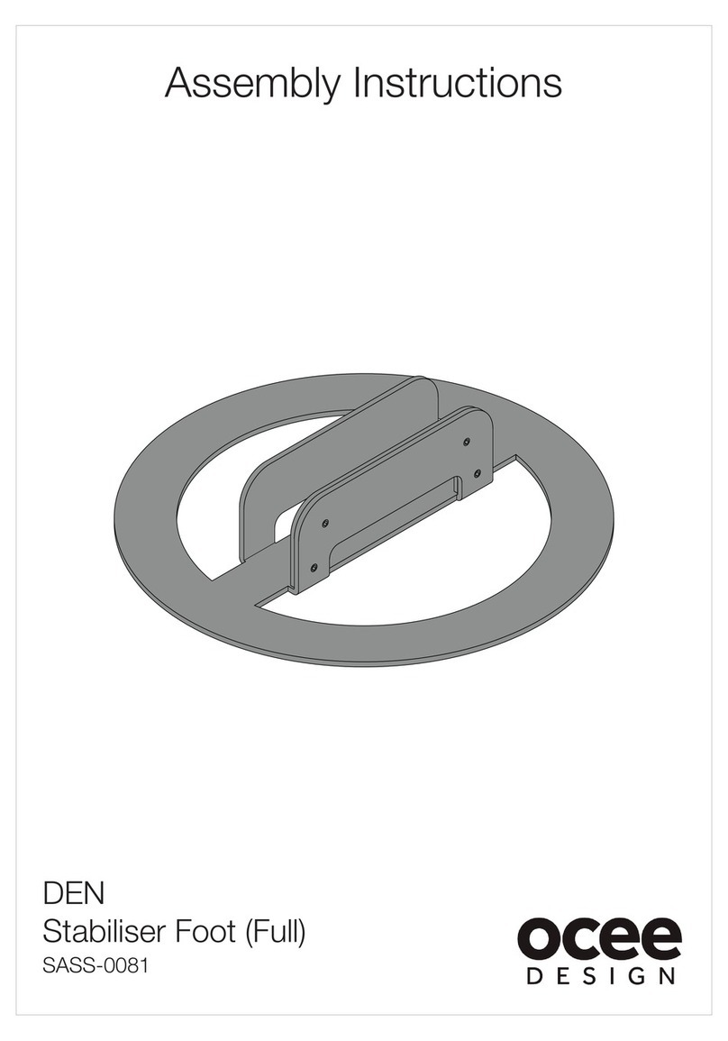
OCEE DESIGN DEN SASS-0081 User manual

OCEE DESIGN

OCEE DESIGN DEN SASS-0081 User manual

OCEE DESIGN SASS-0102 User manual

OCEE DESIGN

OCEE DESIGN SASS-0102 User manual

OCEE DESIGN DEN SASS-0082 User manual

OCEE DESIGN

OCEE DESIGN DEN SASS-0082 User manual

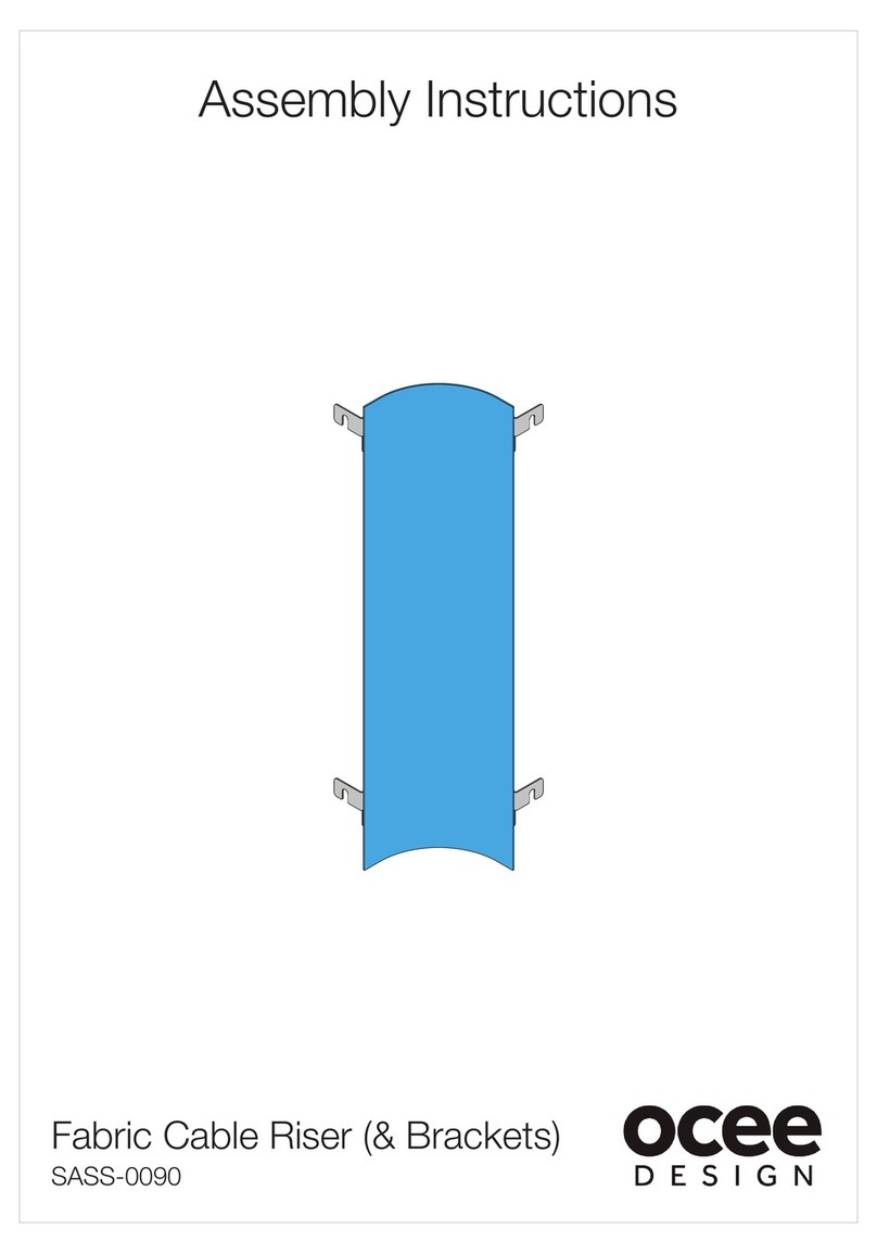
OCEE DESIGN SASS-0090 User manual

OCEE DESIGN

OCEE DESIGN SASS-0090 User manual

OCEE DESIGN SASS-0096 User manual

OCEE DESIGN

OCEE DESIGN SASS-0096 User manual

OCEE DESIGN DEN.Curve 2 Person User manual

OCEE DESIGN

OCEE DESIGN DEN.Curve 2 Person User manual

OCEE DESIGN DEN.Booth SASS-0040 B User manual

OCEE DESIGN

OCEE DESIGN DEN.Booth SASS-0040 B User manual

OCEE DESIGN DEN 675d Module User manual

OCEE DESIGN

OCEE DESIGN DEN 675d Module User manual

OCEE DESIGN DEN.Cube User manual

OCEE DESIGN

OCEE DESIGN DEN.Cube User manual

Popular Office Equipment manuals by other brands

Reiner D53V operating instructions

Reiner

Reiner D53V operating instructions

Meeting Pod 2 Person Pod installation guide

Meeting Pod

Meeting Pod 2 Person Pod installation guide

3-form SimpleSpec 200.60-ILTUO installation manual

3-form

3-form SimpleSpec 200.60-ILTUO installation manual

Jason.L Quadro A Legs 3P 120 Degree Workstation with... Assembly instructions

Jason.L

Jason.L Quadro A Legs 3P 120 Degree Workstation with... Assembly instructions

3-form SimpleSpec 600.01 installation manual

3-form

3-form SimpleSpec 600.01 installation manual

Jason.L Quadro A Legs 3P 120 Degree Workstation with... Assembly instructions

Jason.L

Jason.L Quadro A Legs 3P 120 Degree Workstation with... Assembly instructions

Formax FD 260 Operator's manual

Formax

Formax FD 260 Operator's manual

Martin Yale P-M400000 Operating	 instruction

Martin Yale

Martin Yale P-M400000 Operating instruction

Plus M-18S Service manual

Plus

Plus M-18S Service manual

MBM FC-10 Service manual

MBM

MBM FC-10 Service manual

Hobis MOTION instruction manual

Hobis

Hobis MOTION instruction manual

AMQ Amobi installation guide

AMQ

AMQ Amobi installation guide

promethean ActivPanel Titanium user guide

promethean

promethean ActivPanel Titanium user guide

Formax FD 402TA1 Operator's manual

Formax

Formax FD 402TA1 Operator's manual

Mayline Medina Series Assembly instructions

Mayline

Mayline Medina Series Assembly instructions

Sennheiser SD series Safety instructions

Sennheiser

Sennheiser SD series Safety instructions

Uplift Desk PDC005-TRAY Assembly instructions

Uplift Desk

Uplift Desk PDC005-TRAY Assembly instructions

Plustek SmartOffice PS186 quick start guide

Plustek

Plustek SmartOffice PS186 quick start guide

manuals.online logo
manuals.online logoBrands
  • About & Mission
  • Contact us
  • Privacy Policy
  • Terms and Conditions

Copyright 2025 Manuals.Online. All Rights Reserved.