EWM Trolly 55-5 User manual

Operating instructions
EN
Transport systems
Trolly 55-5
099-008632-EW501
Observe additional system documents!
05.12.2019

General instructions
WARNING
Read the operating instructions!
The operating instructions provide an introduction to the safe use of the products.
•Read and observe the operating instructions for all system components, especially the sa-
fety instructions and warning notices!
•Observe the accident prevention regulations and any regional regulations!
•The operating instructions must be kept at the location where the machine is operated.
•Safety and warning labels on the machine indicate any possible risks.
Keep these labels clean and legible at all times.
•The machine has been constructed to state-of-the-art standards in line with any applicable
regulations and industrial standards. Only trained personnel may operate, service and re-
pair the machine.
•Technical changes due to further development in machine technology may lead to a dif-
fering welding behaviour.
In the event of queries on installation, commissioning, operation or special conditions at the
installation site, or on usage, please contact your sales partner or our customer service
department on +49 2680 181-0.
A list of authorised sales partners can be found at www.ewm-group.com/en/specialist-dealers.
Liability relating to the operation of this equipment is restricted solely to the function of the equipment. No
other form of liability, regardless of type, shall be accepted. This exclusion of liability shall be deemed ac-
cepted by the user on commissioning the equipment.
The manufacturer is unable to monitor whether or not these instructions or the conditions and methods
are observed during installation, operation, usage and maintenance of the equipment.
An incorrectly performed installation can result in material damage and injure persons as a result. For this
reason, we do not accept any responsibility or liability for losses, damages or costs arising from incorrect
installation, improper operation or incorrect usage and maintenance or any actions connected to this in
any way.
© EWM AG
Dr. Günter-Henle-Strasse 8
56271 Mündersbach Germany
Tel.: +49 2680 181-0, Fax: -244
www.ewm-group.com
The copyright to this document remains the property of the manufacturer.
Copying, including extracts, only permitted with written approval.
The content of this document has been prepared and reviewed with all reasonable care. The information
provided is subject to change; errors excepted.

Contents
Notes on the use of these operating instructions
099-008632-EW501
05.12.2019
3
1 Contents
1Contents..................................................................................................................................................3
2For your safety.......................................................................................................................................4
2.1 Notes on the use of these operating instructions ..........................................................................4
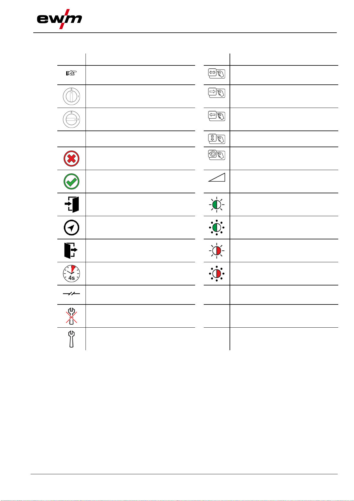
2.2 Explanation of icons.......................................................................................................................5
2.3 Part of the complete documentation..............................................................................................6
3Intended use...........................................................................................................................................7
3.1 Use and operation solely with the following machines..................................................................7
4Machine description –quick overview ................................................................................................8
4.1 Front view / side view from left ......................................................................................................8
5Design and function...............................................................................................................................9
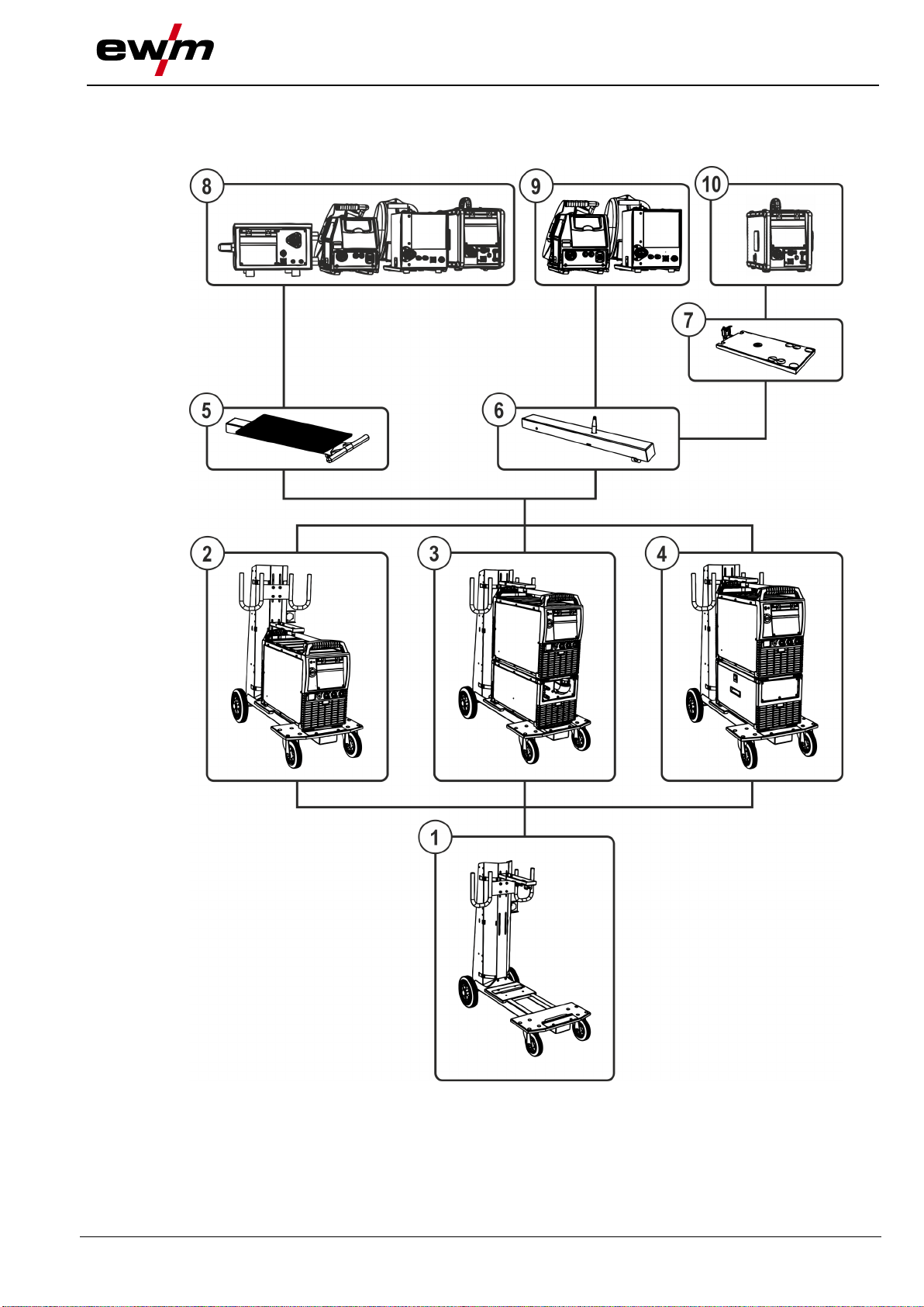
5.1 System overview............................................................................................................................9
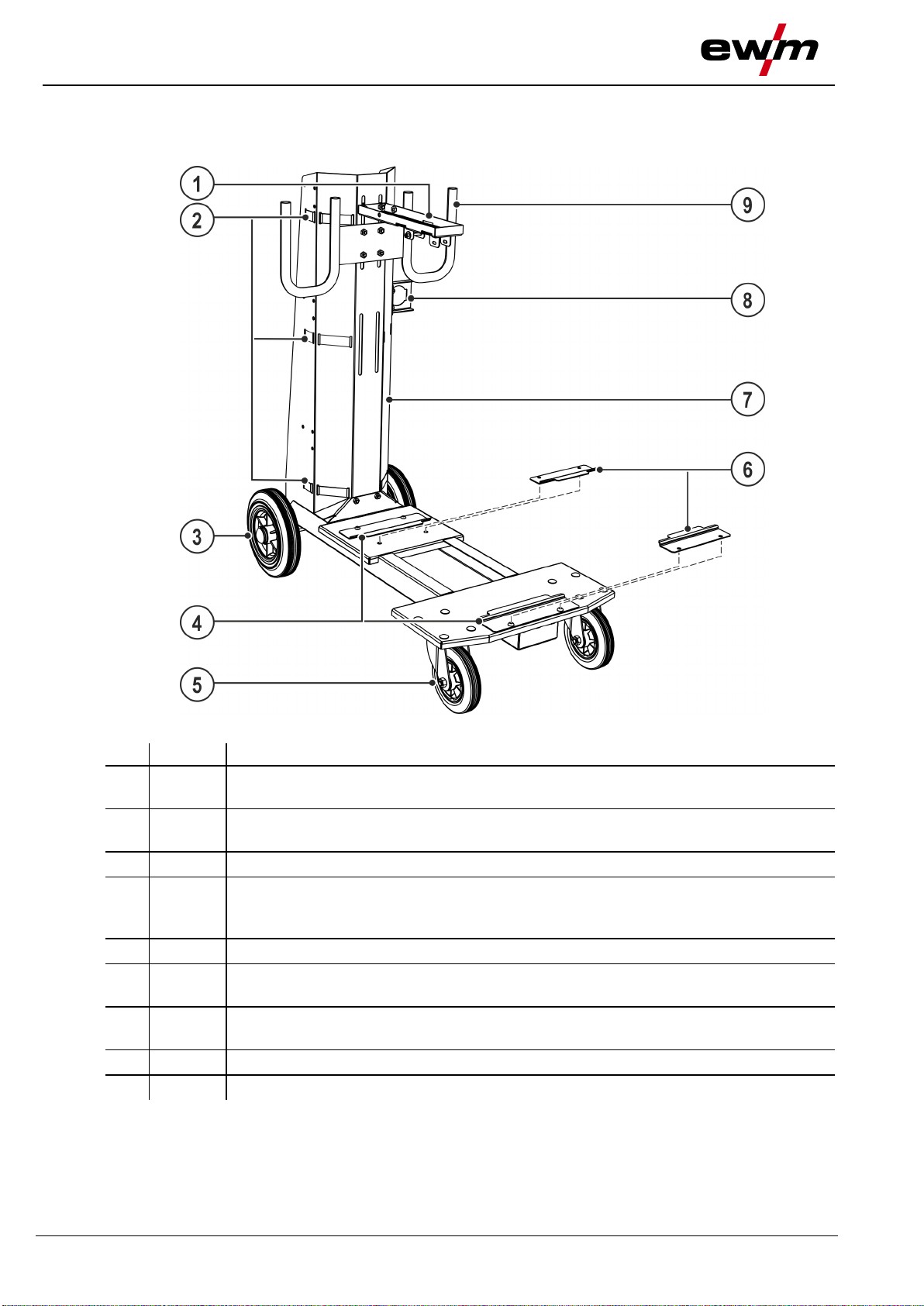
5.2 Assembling the transport cart......................................................................................................11
5.2.1 Final assembly..............................................................................................................12
5.3 Attach the system component to the transport cart.....................................................................13
5.3.1 Intermediate hose package strain relief .......................................................................15
5.3.1.1 Locking the strain relief.................................................................................15
5.4 Securing the shielding gas cylinder.............................................................................................16
5.5 Transport and installation ............................................................................................................17
6Maintenance, care and disposal.........................................................................................................18
6.1 General........................................................................................................................................18
6.1.1 Cleaning .......................................................................................................................18
6.1.2 Dirt filter........................................................................................................................18
6.2 Maintenance work, intervals........................................................................................................19
6.2.1 Daily maintenance tasks ..............................................................................................19
6.2.2 Monthly maintenance tasks..........................................................................................19
6.2.3 Annual test (inspection and testing during operation)..................................................19
6.3 Disposing of equipment ...............................................................................................................20
7Technical data ......................................................................................................................................21
7.1 Trolly 55-5....................................................................................................................................21
8Accessories..........................................................................................................................................22
8.1 General accessories....................................................................................................................22
9Appendix...............................................................................................................................................23
9.1 Searching for a dealer .................................................................................................................23

For your safety
Notes on the use of these operating instructions
4
099-008632-EW501
05.12.2019
2 For your safety
2.1 Notes on the use of these operating instructions
DANGER
Working or operating procedures which must be closely observed to prevent imminent
serious and even fatal injuries.
•Safety notes include the "DANGER" keyword in the heading with a general warning symbol.
•The hazard is also highlighted using a symbol on the edge of the page.
WARNING
Working or operating procedures which must be closely observed to prevent serious
and even fatal injuries.
•Safety notes include the "WARNING" keyword in the heading with a general warning sym-
bol.
•The hazard is also highlighted using a symbol in the page margin.
CAUTION
Working or operating procedures which must be closely observed to prevent possible
minor personal injury.
•The safety information includes the "CAUTION" keyword in its heading with a general warn-
ing symbol.
•The risk is explained using a symbol on the edge of the page.
Technical aspects which the user must observe to avoid material or equipment damage.
Instructions and lists detailing step-by-step actions for given situations can be recognised via bullet
points, e.g.:
•Insert the welding current lead socket into the relevant socket and lock.

For your safety
Explanation of icons
099-008632-EW501
05.12.2019
5
2.2 Explanation of icons
Symbol
Description
Symbol
Description
Indicates technical aspects which the
user must observe.
Activate and release / Tap / Tip
Switch off machine
Release
Switch on machine
Press and hold
Switch
Incorrect / Invalid
Turn
Correct / Valid
Numerical value –adjustable
Input
Signal light lights up in green
Navigation
Signal light flashes green
Output
Signal light lights up in red
Time representation (e.g.: wait 4 s /
actuate)
Signal light flashes red
Interruption in the menu display (other
setting options possible)
Tool not required/do not use
Tool required/use

For your safety
Part of the complete documentation
6
099-008632-EW501
05.12.2019
2.3 Part of the complete documentation
These operating instructions are part of the complete documentation and valid only in
combination with all other parts of these instructions! Read and observe the operating
instructions for all system components, especially the safety instructions!
The illustration shows a general example of a welding system.
Figure 2-1
Item
Documentation
A.1
Wire feeder
A.2
Conversion instructions
A.3
Power source
A.4
Cooling unit, voltage converter, tool box etc.
A.5
Trolley
A.6
Welding torch
A.7
Remote control
A.8
Control
A
Complete documentation

Intended use
Use and operation solely with the following machines
099-008632-EW501
05.12.2019
7
3 Intended use
WARNING
Hazards due to improper usage!
The machine has been constructed to the state of the art and any regulations and
standards applicable for use in industry and trade. It may only be used for the welding
procedures indicated at the rating plate. Hazards may arise for persons, animals and
material objects if the equipment is not used correctly. No liability is accepted for any
damages arising from improper usage!
•The equipment must only be used in line with its designated purpose and by trained or
expert personnel!
•Do not improperly modify or convert the equipment!
To transport arc welding systems and process-dependent components such as shielding gas cylinders.
3.1 Use and operation solely with the following machines
One of the listed power sources must always be used on the transport cart as the basic module. The cur-
rent sources can be expanded with further modules.
•Phoenix 355, -405, -505 [1] [2] [3]
•Taurus 355, -405, -505 [1] [2] [3]
•Picomig 185, -355 [1]
•Picotig 200 AC/DC[3] [4]
•Tetrix 230[3] [4]
[1] Can be combined with a cooling unit cool50, a toolbox ON Case or a voltage converter voltConver-
ter 230/400
[2] Can be combined with a wire feeder drive (expandable optionally)
[3] Can be combined with a wire feeder tigSpeed (expandable optionally)
[4] Can be combined with a cooling unit cool40, -41
For systems equipped with a wire feeder, additional options have to be retro-fitted. See the
system overview for the relevant options and combinations > see 5.1 chapter.

Machine description –quick overview
Front view / side view from left
8
099-008632-EW501
05.12.2019
4 Machine description – quick overview
4.1 Front view / side view from left
Figure 4-1
Item
Symbol
Description 0
1
Cross arm
Upper device attachment
2
Securing element
Clamping belt for attaching the shielding gas cylinder
3
Wheels, fixed castors
4
Support bracket (BK260)
Lower device attachment (Picomig 185, -355; Phoenix 355, -405, -505;
Taurus 355, -405, -505; cool50)
5
Wheels, guide castors
6
Support bracket (BK210)
Lower device attachment (Picotig 200 AC; Tetrix 230; cool40, -41)
7
Shielding gas cylinder holder > see 5.4 chapter
Carrier plate for the shielding gas cylinder
8
Intermediate hose package strain relief > see 5.3.1 chapter
9
Hose package holder

Design and function
System overview
099-008632-EW501
05.12.2019
9
5 Design and function
5.1 System overview
Figure 5-1

Design and function
System overview
10
099-008632-EW501
05.12.2019
Item
Symbol
Description 0
1
Transport cart
2
Transport cart + one system component (e.g. power source)
3
Transport cart + two system components (e.g. power source + cooling module)
4
Transport cart + one system component (e.g. toolbox + power source)
5
Cross arm and holder for wire feeder
6
Pivot support (360°) for wire feeders
7
Pivot support for a wire feeders D200
8
All wire feeders - drive
9
Wire feeder (rotatable) - drive 4L/4X
10
Wire feeder (rotatable) - drive 200

Design and function
Assembling the transport cart
099-008632-EW501
05.12.2019
11
5.2 Assembling the transport cart
WARNING
Improper work carried out!
In the event of improper work carried out on the display stand, the display stand may
lose stability, tip over and result in serious injury!
•Only use the construction and fitting parts supplied!
•Do not load the display stand without reinforcement panels affixed!
Figure 5-2

Design and function
Assembling the transport cart
12
099-008632-EW501
05.12.2019
Figure 5-3
Item 0
Quan-
tity
Description
Item number
1
12
M8 x 16, hexagonal pan screw
094-007803-00000
2
12
Fender washer
064-000793-00000
5.2.1 Final assembly
WARNING
Danger due to failure to carry out the final inspection!
Parts that are incorrectly fitted or that become loose are a source of danger.
•Check all mechanical connections to ensure that they are fitted correctly!
•Carry out the final inspection!
•Carry out the functional test!

Design and function
Attach the system component to the transport cart
099-008632-EW501
05.12.2019
13
5.3 Attach the system component to the transport cart
CAUTION
Improperly secured equipment!
Equipment, equipment combinations and accessories incorrectly fastened onto trans-
port systems can tip over during transport and cause injuries!
•Only used the original parts supplied to fasten the equipment.
•Use the systems only for transporting the machines > see 3.1 chapter.
•Check the fixing points before each transport and at regular intervals.
This transport system is designed to accommodate modular device systems.
The standard version allows the fitting of up to two system components (e.g. power source and
cooling module or an identical module) to the transport cart. The modules are attached to the
transport cart using device-dependent support brackets and the height-adjustable cross arm.
Attaching added options allows the combination of further devices or modules > see 5.1 chapter.
Figure 5-4
Item
Symbol
Description 0
1
Support bracket (BK260)
Lower device attachment (Picomig 185, -355; Phoenix 355, -405, -505;
Taurus 355, -405, -505; cool50)
2
Support bracket (BK210)
Lower device attachment (Picotig 200 AC; Tetrix 230; cool40, -41)
3
Machine support
•Unscrew the support bracket.
The further use of the support bracket depends on the system components to be used (please note
the device assignment of the support bracket BK260/BK210). The attachment with the front and rear
support brackets BK260 is shown below as an example.

Design and function
Attach the system component to the transport cart
14
099-008632-EW501
05.12.2019
Figure 5-5
Item
Symbol
Description 0
1
Support bracket (BK260)
Lower device attachment (Picomig 185, -355; Phoenix 355, -405, -505;
Taurus 355, -405, -505; cool50)
2
Pan screw, M8 x 16 mm
3
Cross arm
Upper device attachment
4
System components
Power source
5
Cylinder head screw, M6 x 45
6
Fender washer
7
Grip bar
8
Hexagon nut, M6
•Place the system component with the device feet on the device carrier and secure in the rear support
brackets.
•Fix the device feet of the system component with the front support bracket.
•Adapt the cross arm height to the height of the system component.
•Screw the tube handle of the system component to the cross arm.

Design and function
Attach the system component to the transport cart
099-008632-EW501
05.12.2019
15
5.3.1 Intermediate hose package strain relief
Property damage due to strain relief not installed or not installed correctly!
The strain relief absorbs tensile forces on cables, plugs and sockets.
If strain reliefs are not installed or not installed correctly, the connector plugs or sockets may be
damaged.
•The attachment must always take place on both sides of the intermediate hose package!
•The connections of the hose package must be locked properly!
5.3.1.1 Locking the strain relief
Figure 5-6
•Secure hose package end with the strain relief.

Design and function
Securing the shielding gas cylinder
16
099-008632-EW501
05.12.2019
5.4 Securing the shielding gas cylinder
WARNING
Risk of injury due to improper handling of shielding gas cylinders!
Improper handling and insufficient securing of shielding gas cylinders
can cause serious injuries!
•Secure shielding gas cylinders using the standard fastening elements on
the unit (chain/belt)!
•Two fastening elements have to be used! Adjust the position of the faste-
ning elements to the shielding gas cylinder size!
•The fastening elements must tightly enclose the shielding gas cylinder.
Figure 5-7
Item
Symbol
Description 0
1
Shielding gas cylinder
2
Securing element
Clamping belt for attaching the shielding gas cylinder
3
Shielding gas cylinder holder
Carrier plate for the shielding gas cylinder
•Open the tension closure on the straps.
•Place the shielding gas cylinder on the retainer.
•Secure shielding gas cylinder with clamping belts (ensure that the clamping belts are firmly seated!).

Design and function
Transport and installation
099-008632-EW501
05.12.2019
17
5.5 Transport and installation
WARNING
Risk of accident due to improper transport of machines that must not be lifted!
Do not lift or suspend the machine! The machine can drop and cause injuries! The
handles, straps or brackets are suitable for transport by hand only!
•The machine must not be suspended or lifted using a crane.
CAUTION
Risk of accidents due to improperly secured machines!
Depending on the machine series the transport vehicle has to
be adapted to mount the machine. Failing to adapt the trans-
port vehicle can cause the machine being transported to topp-
le and lead to injuries!
•Following conversions and prior to each transport make sure all
mounting elements are properly tightened!
Risk of accidents due to supply lines!
During transport, attached supply lines (mains leads, control cables, etc.) can cause
risks, e.g. by causing connected machines to tip over and injure persons!
•Disconnect all supply lines before transport!
Figure 5-8

Maintenance, care and disposal
General
18
099-008632-EW501
05.12.2019
6 Maintenance, care and disposal
6.1 General
DANGER
Risk of injury due to electrical voltage after switching off!
Working on an open machine can lead to fatal injuries!
Capacitors are loaded with electrical voltage during operation. Voltage remains present
for up to four minutes after the mains plug is removed.
1. Switch off machine.
2. Remove the mains plug.
3. Wait for at last 4 minutes until the capacitors have discharged!
WARNING
Incorrect maintenance, testing and repair!
Maintenance, testing and repair of the machine may only be carried out by skilled and
qualified personnel. A qualified person is one who, because of his or her training, know-
ledge and experience, is able to recognise the dangers that can occur while testing
welding power sources as well as possible subsequent damage, and who is able to im-
plement the required safety procedures.
Observe the maintenance instructions > see 6.2 chapter.
•In the event that the provisions of one of the below-stated tests are not met, the machine
must not be operated again until it has been repaired and a new test has been carried out!
Repair and maintenance work may only be performed by qualified authorised personnel; otherwise the
right to claim under warranty is void. In all service matters, always consult the dealer who supplied the
machine. Return deliveries of defective equipment subject to warranty may only be made through your
dealer. When replacing parts, use only original spare parts. When ordering spare parts, please quote the
machine type, serial number and item number of the machine, as well as the type designation and item
number of the spare part.
Under the specified ambient conditions and normal working conditions this machine is essentially mainte-
nance-free and requires just a minimum of care.
Contamination of the machine may impair service life and duty cycle. The cleaning intervals depend on
the ambient conditions and the resulting contamination of the machine. The minimum interval is every six
months.
6.1.1 Cleaning
•Clean the outer surfaces with a moist cloth (no aggressive cleaning agents).
•Purge the machine venting channel and cooling fins (if present) with oil- and water-free compressed
air. Compressed air may overspeed and destroy the machine fans. Never direct the compressed air
directly at the machine fans. Mechanically block the fans, if required.
•Check the coolant for contaminants and replace, if necessary.
6.1.2 Dirt filter
The duty cycle of the welding machine decreases as an effect of the reduced cooling air volume. The dirt
filter must be remove at regular intervals and cleaned by blowing out with compressed air (depending on
the level of soiling).

Maintenance, care and disposal
Maintenance work, intervals
099-008632-EW501
05.12.2019
19
6.2 Maintenance work, intervals
6.2.1 Daily maintenance tasks
Visual inspection
•Mains supply lead and its strain relief
•Gas cylinder securing elements
•Check hose package and power connections for exterior damage and replace or have repaired by
specialist staff as necessary!
•Gas tubes and their switching equipment (solenoid valve)
•Check that all connections and wearing parts are hand-tight and tighten if necessary.
•Check correct mounting of the wire spool.
•Wheels and their securing elements
•Transport elements (strap, lifting lugs, handle)
•Other, general condition
Functional test
•Operating, message, safety and adjustment devices (Functional test)
•Welding current cables (check that they are fitted correctly and secured)
•Gas tubes and their switching equipment (solenoid valve)
•Gas cylinder securing elements
•Check correct mounting of the wire spool.
•Check that all screw and plug connections and replaceable parts are secured correctly, tighten if ne-
cessary.
•Remove any spatter.
•Clean the wire feed rollers on a regular basis (depending on the degree of soiling).
6.2.2 Monthly maintenance tasks
Visual inspection
•Casing damage (front, rear and side walls)
•Wheels and their securing elements
•Transport elements (strap, lifting lugs, handle)
•Check coolant tubes and their connections for impurities
Functional test
•Selector switches, command devices, emergency stop devices, voltage reducing devices, message
and control lamps
•Check wire guide elements (wire feed roll holder, wire feed nipple, wire guide tube) for tight fit.
Recommendation for replacing the wire feed roll holder (eFeed) after 2000 hours of operation, see re-
placement parts).
•Check coolant tubes and their connections for impurities
•Check and clean the welding torch. Deposits in the torch can cause short circuits and have a negative
impact on the welding result, ultimately causing damage to the torch.
6.2.3 Annual test (inspection and testing during operation)
A periodic test according to IEC 60974-4 "Periodic inspection and test" has to be carried out. In addition
to the regulations on testing given here, the relevant local laws and regulations must also be observed.
For more information refer to the "Warranty registration" brochure supplied and our information regarding
warranty, maintenance and testing at www.ewm-group.com!

Maintenance, care and disposal
Disposing of equipment
20
099-008632-EW501
05.12.2019
6.3 Disposing of equipment
Proper disposal!
The machine contains valuable raw materials, which should be recycled, and electronic com-
ponents, which must be disposed of.
•Do not dispose of in household waste!
•Observe the local regulations regarding disposal!
•According to European provisions (Directive 2012/19/EU on Waste of Electrical and Electronic
Equipment), used electric and electronic equipment may no longer be placed in unsorted municipal
waste. It must be collected separately. The symbol depicting a waste container on wheels indicates
that the equipment must be collected separately.
This machine has to be disposed of, or recycled, in accordance with the waste separation systems in
use.
•According to German law (law governing the distribution, taking back and environmentally correct dis-
posal of electric and electronic equipment (ElektroG)), used machines are to be placed in a collection
system separate from unsorted municipal waste. The public waste management utilities (communities)
have created collection points at which used equipment from private households can be disposed of
free of charge.
•Information about returning used equipment or about collections can be obtained from the respective
municipal administration office.
•In addition to this, returns are also possible throughout Europe via EWM sales partners.
Table of contents
Other EWM Welding Accessories manuals

EWM
EWM Drive XQ User manual

EWM
EWM TROLLY 70-1 User manual

EWM
EWM UM 24 G EZA User manual

EWM
EWM T5.01-DC Comfort 3.0 User manual

EWM
EWM TIGSPEED OSCILLATION DRIVE 45 COLDWIRE User manual

EWM
EWM Trolly 55-6 DF User manual

EWM
EWM TH AMT User manual

EWM
EWM cool40 U31 User manual

EWM
EWM miniDrive GS User manual

EWM
EWM cool50 U42 User manual

EWM
EWM TIG 17 G User manual

EWM
EWM TIGSPEED OSCILLATION DRIVE 45 COLDWIRE User manual

EWM
EWM BUSINT X11 User manual

EWM
EWM L1.04 - RC XQ Expert 2.0 User manual

EWM
EWM voltConverter 230/400 User manual

EWM
EWM PHB 50 20 A User manual

EWM
EWM TROLLY 31-2/35-2 User manual

EWM
EWM T5.00 User manual

EWM
EWM Tetrix drive 4L User manual

EWM
EWM TIG-SR 300 GD HD User manual