EXFO IQ Series User manual

Form 080/01
Complimentary Reference Material
This PDF has been made available as a complimentary service for you to assist in
evaluating this model for your testing requirements.
T G offers a wide range of test equipment solutions, from renting short to long
term, buying refurbished and purchasing new. Financing options, such as
Financial Rental, and Leasing are also available on application.
T G will assist if you are unsure whether this model will suit your requirements.
Call T G if you need to organise repair and/or calibrate your unit.
If you click on the “Click-to-Call” logo below, you can all us for FREE!
TMG Corporate Website TMG Products Website
Disclaimer:
All trademarks appearing within this PDF are trademarks of their respective owners.

Instruction Manual
Januar
y
2000
P/N: MAN-117-I .4ACE
Fourth Edition
IQ Li
g
ht Source Series
IQ-2100 Li
g
ht Source
IQ-2300 ASE Source
IQ-2400 WDM Laser Source
IQ-2600 Tunable Laser Source
IQ-2100, IQ-2300, IQ-2400, and IQ-2600

!"
#
$%&!%&"
'(!'")*+%,
'-
./)))
01
#
1

CONTENTS
IQ Light Source Series iii
CONTENTS
Certification Information .................................................................................................... ix
1I
NTRODUCTION ..........................................................................................................................1-1
1.1 IQ-200 Optical Test System Product Line ......................................................................1-1
1.2 Unpacking and Inspection ..............................................................................................1-2
1.3 Safety Conventions .........................................................................................................1-2
1.4 Transportation and Storage ............................................................................................1-3
1.5 Safety Information ...........................................................................................................1-3
1.6 Transportation and Storage ............................................................................................1-7
1.7 Getting Help ....................................................................................................................1-8
2P
RELIMINARY INFORMATION .......................................................................................................2-1
2.1 Module Descriptions .......................................................................................................2-1
2.2 Front Panel Descriptions ..............................................................................................2-12
2.3 Module Insertion ...........................................................................................................2-16
2.4 Optical Connections ......................................................................................................2-16
2.5 Polarization Maintaining Laser Connectorization (IQ-2400 Only) .................................2-19
2.6 Module Removal ...........................................................................................................2-22
3S
AFETY MEASURES (IQ-2300 AND IQ-2400) .............................................................................3-1
3.1 Description of Safety Measures ......................................................................................3-1
3.2 Source Activation with Security Measures ......................................................................3-4
4O
PERATION (IQ-2100) ...............................................................................................................4-1
4.1 Loading the Application Software ...................................................................................4-1
4.2 Main Window Description ...............................................................................................4-2
4.3 Monitor Window Description ...........................................................................................4-6
4.4 Exiting the Application Software .....................................................................................4-8
4.5 Source Activation/Deactivation .......................................................................................4-8
4.6 Source Setup ..................................................................................................................4-9
5O
PERATION (IQ-2300) ...............................................................................................................5-1
5.1 Loading the Application Software ...................................................................................5-1
5.2 Main Window Description ...............................................................................................5-2
5.3 Monitor Window Description ...........................................................................................5-7
5.4 Exiting the Application Software .....................................................................................5-8
5.5 Source Activation/Deactivation .......................................................................................5-9
5.6 Source Setup ..................................................................................................................5-9

CONTENTS
iv IQ-2100, IQ-2300, IQ-2400, and IQ-2600
6O
PERATION (IQ-2400) .............................................................................................................. 6-1
6.1 Theory ............................................................................................................................6-1
6.2 Loading the Application Software ...................................................................................6-3
6.3 Main Window Description ............................................................................................... 6-4
6.4 Monitor Window Description ........................................................................................6-11
6.5 Exiting the Application Software ...................................................................................6-12
6.6 Source Activation/Deactivation ....................................................................................6-13
6.7 Setup ............................................................................................................................6-13
6.8 Setpoints ......................................................................................................................6-17
6.9 Set Power .....................................................................................................................6-19
6.10 Reference Mode vs. Absolute Mode ............................................................................6-20
6.11 Source Parameters ......................................................................................................6-21
6.12 Source Synchronization ...............................................................................................6-23
7O
PERATION (IQ-2600) .............................................................................................................. 7-1
7.1 Loading the Application Software ...................................................................................7-1
7.2 Main Window Description ............................................................................................... 7-2
7.3 Parameter Definition Controls ........................................................................................7-8
7.4 Monitor Window Description ........................................................................................7-10
7.5 Exiting the Application Software ...................................................................................7-11
7.6 Source Activation/Deactivation ....................................................................................7-12
7.7 Wavelength Selection ..................................................................................................7-12
7.8 Sweep Selection ..........................................................................................................7-14
7.9 Programmed Operation ................................................................................................7-15
7.10 User Calibration ........................................................................................................... 7-17
7.11 ASE Mode ....................................................................................................................7-18
8R
EMOTE CONTROL COMMANDS .................................................................................................8-1
8.1 SCPI Commands ...........................................................................................................8-1
8.2 Quick Reference Command Trees ...............................................................................8-72
8.3 Error Messages ............................................................................................................8-82
8.4 GPIB Troubleshooting ..................................................................................................8-85
9M
AINTENANCE AND TROUBLESHOOTING ....................................................................................9-1
9.1 General Maintenance .....................................................................................................9-1
9.2 Cleaning the Optical Ports .............................................................................................9-1
9.3 Source Verification and Recalibration ............................................................................9-2
9.4 Troubleshooting .............................................................................................................9-3
10 TECHNICAL SPECIFICATIONS .................................................................................................... 10-1
10.1 IQ-2100 Light Source ...................................................................................................10-1
10.2 IQ-2300 ASE Source ....................................................................................................10-5

CONTENTS
IQ Light Source Series v
10.3 IQ-2400 WDM Laser Source ........................................................................................10-7
10.4 IQ-2600 Tunable Laser Source ..................................................................................10-14
11 WARRANTY .............................................................................................................................11-1
11.1 General Information ......................................................................................................11-1
11.2 Liability ..........................................................................................................................11-2
11.3 Exclusions .....................................................................................................................11-2
11.4 Certification ...................................................................................................................11-2
11.5 Service and Repairs .....................................................................................................11-2
GLOSSARY ......................................................................................................................GLOSSARY-1
INDEX ......................................................................................................................................INDEX-1

FIGURES
vi IQ-2100, IQ-2300, IQ-2400, and IQ-2600
FIGURES
Figure 1-1. Class 1 Laser Product Indication .....................................................................1-4
Figure 1-2. Class 1 Laser Product Indication .....................................................................1-4
Figure 1-3. Class 1 LED Product Indication .......................................................................1-5
Figure 1-4. Class 3A Safety Sticker ...................................................................................1-6
Figure 1-5. Class IIIB Safety Sticker .................................................................................. 1-7
Figure 2-1. Module Nameplate ........................................................................................... 2-1
Figure 2-2. Laser Radiation Warning Sticker .....................................................................2-4
Figure 2-3. Laser Radiation Warning Sticker .....................................................................2-5
Figure 2-4. IQ-2100 Light Source .....................................................................................2-12
Figure 2-5. IQ-2300 ASE Source .....................................................................................2-12
Figure 2-6. IQ-2400 WDM Laser Source .........................................................................2-13
Figure 2-7. IQ-2600 Tunable Laser Source .....................................................................2-13
Figure 2-8. Laser Radiation Hazard Sticker .....................................................................2-14
Figure 2-9. EUI Base Plate Options .................................................................................2-17
Figure 2-10. EUI Connector Adaptor ..................................................................................2-18
Figure 2-11. Mounting EUI Connector Adaptor ..................................................................2-18
Figure 2-12. IQ-2400: FC/APC Connector Option .............................................................2-19
Figure 2-13. IQ-2400: SC/APC Connector Option .............................................................2-20
Figure 2-14. IQ-2400: E-2000/APC Connector Option .......................................................2-20
Figure 2-15. IQ-2400: EUI Connector Option .....................................................................2-21
Figure 2-16. Removing an IQ Module ................................................................................ 2-22
Figure 3-1. IQ-2300 and IQ-2400 Interlock State Display ..................................................3-2
Figure 3-2. IQ-2300 and IQ-2400 Master Control State Display ........................................3-3
Figure 3-3. Interlock Status Icon ........................................................................................3-4
Figure 3-4. Light Source Activation/Deactivation Buttons and Status Box .........................3-5
Figure 3-5. Interlock Status Icon ........................................................................................3-5
Figure 3-6. On/Off Button and Status Indicator .................................................................. 3-6
Figure 4-1. Main Window (IQ-2100) ...................................................................................4-2
Figure 4-2. Monitor Window (IQ-2100) ............................................................................... 4-7
Figure 4-3. Light Source Activation/Deactivation Buttons and Status Box .........................4-9
Figure 4-4. Increase/Decrease Buttons and Attenuation Edit Box ...................................4-10
Figure 4-5. Modulation List Box .......................................................................................4-10
Figure 4-6. Wavelength Radio Button and Box ................................................................4-11
Figure 5-1. Main Window (IQ-2300) ...................................................................................5-2
Figure 5-2. Monitor Window (IQ-2300) ............................................................................... 5-7
Figure 5-3. Light Source Activation/Deactivation Buttons and Status Box .........................5-9
Figure 5-4. Increase/Decrease Buttons and Attenuation Edit Box ...................................5-10
Figure 5-5. Wavelength Box .............................................................................................5-10

FIGURES
IQ Light Source Series vii
Figure 6-1. Main Window (IQ-2400) ...................................................................................6-4
Figure 6-2. Monitor Window (IQ-2400) .............................................................................6-11
Figure 6-3. On/Off Button and Status Indicator ................................................................6-13
Figure 6-4. Control Page ..................................................................................................6-14
Figure 6-5. Modulation Page ............................................................................................6-15
Figure 6-6. Step Page ......................................................................................................6-16
Figure 6-7. New Setpoint Dialog Box ...............................................................................6-18
Figure 6-8. Set Power Dialog Box ....................................................................................6-19
Figure 6-9. Source Synchronization with External Signal Generator ................................6-23
Figure 6-10. Source Synchronization with Signal Generated by IQ-2400 Module .............6-24
Figure 7-1. Main Window (IQ-2600 Tunable Mode) ...........................................................7-2
Figure 7-2. Main Window (IQ-2600 ASE Mode) .................................................................7-3
Figure 7-3. Main Window (IQ-2600 Sweeping) ...................................................................7-4
Figure 7-4. Monitor Window (IQ-2600) .............................................................................7-10
Figure 7-5. On/Off Button and Status Indicator ................................................................7-12
Figure 7-6. Setup Window ................................................................................................7-13
Figure 7-7. Sweep Setup Window ....................................................................................7-14
Figure 7-8. Program Settings Window ..............................................................................7-15
Figure 7-9. Auto Step Dialog Box .....................................................................................7-16
Figure 7-10. User Calibration Menu ....................................................................................7-17
Figure 7-11. Main Window (IQ-2600 ASE Mode) ...............................................................7-18

'2

CERTIFICATION INFORMATION
IQ Light Source Series ix
CERTIFICATION INFORMATION
'%
3/4!5 6"%%7'
'
8
2
8
9
WARNING
'9
98
8
:'*
;%'-
'%
3<%

'2

INTRODUCTION
IQ Light Source Series 1-1
!""#$%&
1I
NTRODUCTION
!" =*5
5
> =?/))*5
> =?,))55
> =?@))1<;*5
> =?A))'*5
B
C
>
>
> 9
>
' =*55'
=*55
1.1 IQ-200 Optical Test System Product Line
' =?))'5
'21D =
5 =?))'5
9'
=?),; =?)A
9:9
=?)A9: =?)A3%9%
=?))'5 =5
!""#$'

INTRODUCTION
1-2 IQ-2100, IQ-2300, IQ-2400, and IQ-2600
()*
1.2 Unpacking and Inspection
' =*55
C
> ;
> 22
> %%
> 2
> %
> '
'
72
8
1.3 Safety Conventions
'C
WARNING 7( 8
-<
WARNING
8
CAUTION 7( 8
<
CAUTION
8
IMPORTANT 7
2

INTRODUCTION
IQ Light Source Series 1-3
$*
1.4 Transportation and Storage
;
''
(C
> 322
> 5
> E
> 2
1.5 Safety Information
WARNING
!"
CAUTION
#$%
&
CAUTION
# &
1.5.1 Class I Laser Products
'?/%7%
?/%7/)@)/)/)@)// %+?4/C/00,*
> =?/))*5!*<
"
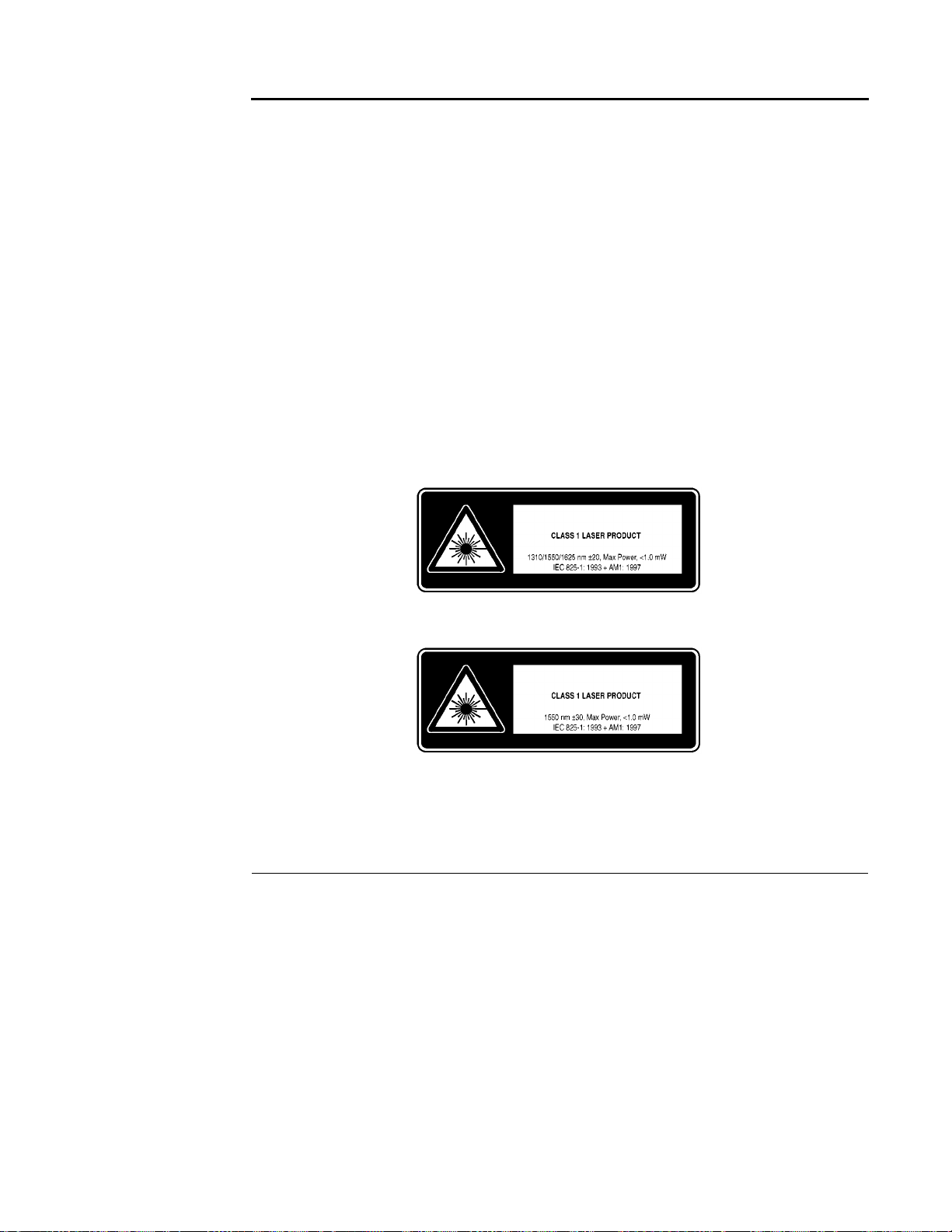
INTRODUCTION
1-4 IQ-2100, IQ-2300, IQ-2400, and IQ-2600
> =?@),6*<993)1<;*5!
"
> =?A))'*5
'2-
9#9
WARNING
!"
#$%$
&
'%/9///?/,
=?/)) =?@),6*<993)
=?@),6*<993/ =?@),6*<993? =?A))
Figure 1-1. Class 1 Laser Product Indication
Figure 1-2. Class 1 Laser Product Indication

INTRODUCTION
IQ Light Source Series 1-5
Figure 1-3. Class 1 LED Product Indication
1.5.2 Class 3A Laser Products (IEC 825)
'%,
%+?4/C/00,F;/C/00G
> =?,))55!0+)
"
> =?@),6*<993@1<;*5!"
*/44)
9:
2%,1
WARNING
!"
#$%$
&
'%,552/@
=?,)) =?@),6*<993@

INTRODUCTION
1-6 IQ-2100, IQ-2300, IQ-2400, and IQ-2600
Figure 1-4. Class 3A Safety Sticker
1.5.3 Class IIIB Laser Products (FDA onl
y
)
'% 6
?/%7/)@)/)'
9
> =?,))55!0+)
"
> =?@),6*<993@1<;*5!"
*/44)
9:
2%,1
WARNING
!"
#$%$
&
'% 6552/4
=?,)) =?@),6*<993@
INVISIBLE LASER RADIATION
DO NOT STARE INTO BEAM OR VIEW
DIRECTLY WITH OPTICAL INSTRUMENTS
CLASS 3A LASER PRODUCT
λ
1520-1570 nm
25 mW
21 CFR 1040.10 AND 1040.11
IEC
825-1: 1993

INTRODUCTION
IQ Light Source Series 1-7
$*
Figure 1-5. Class IIIB Safety Sticker
1.6 Transportation and Storage
;
''
(C
> 322
> 5
>
2
INVISIBLE LASER RADIATION
DO NOT STARE INTO BEAM OR VIEW
DIRECTLY WITH OPTICAL INSTRUMENTS
CLASS 3A LASER PRODUCT
λ
1520-1570 nm
25 mW
21 CFR 1040.10 AND 1040.11
IEC
825-1: 1993

INTRODUCTION
1-8 IQ-2100, IQ-2300, IQ-2400, and IQ-2600
+*,
1.7 Getting Help
%5&
GC,)+C))!5'";
@A4&
H=%&/;,&G
%
/+))AA,,0,A!:5%"
'C!@/+"A+,)?//
9C!@/+"A+,?/G)
I9
9
%$*;(
/))%
G+,4,JJ
'C,,/,@A,))?)
9C,,/,@A40)0,

PRELIMINARY INFORMATION
IQ Light Source Series 2-1
'
2P
RELIMINARY INFORMATION
2.1 Module Descriptions
' =5*
1 =5
=?),3% =?)A3%9
7 =?/)) =?,)) =?@))
C
>&36
K
> 75?,?9
> 1*!-*2"
> 1<<!<<9"
K*H 1';8 =?/)) =?@))
3 !""+%-.+
=
' ?/
Figure 2-1. Module Nameplate
Ver.
Mfg.
date
P/N
S/N
Made in Canada QST-94
465 Godin Ave.
Vanier, Que., Canada G1M 3G7
This device complies with part 15 of the FCC rules. Operation is
subject to the following two conditions: (1) this device may not cause
harmful interference and (2) this device must accept any interference
received, including interference that may cause undesired operation.
(identifying configuration
and connector type)
Serial number
Product version
Manufacturing date
Source type
and wavelength
Part number
IQ-2123BLC-70
DUAL LASER 1310/1550 NM
31641A-10
K-1.0
JANUARY 1998
Other manuals for IQ Series
1
This manual suits for next models
4
Table of contents
Other EXFO Laboratory Equipment manuals


