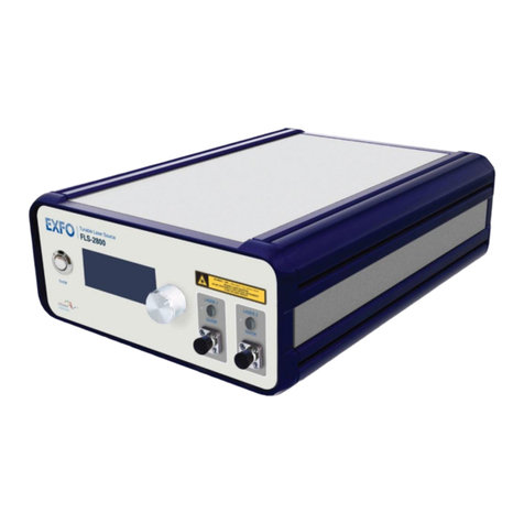
EXFO IQS-636 User manual


Modular Tunable Laser Source Platform
IQS-636
i
Copyright © 2009-2015 EXFO Inc. All rights reserved. No part of this publication may be reproduced,
stored in a retrieval system ortransmitted in any form, be it electronically, mechanically, or by any
other means such as photocopying, recording or otherwise, without the prior written permission of
EXFO Inc. (EXFO).
Information provided by EXFO is believed to be accurate and reliable.
However, no responsibility is assumed by EXFO for its use nor for any infringements of patents or
other rights of third parties that may result from its use. No license is granted by implicationor
otherwise under any patent rights of EXFO.
EXFO’s Commerce And Government Entities (CAGE)code under the North Atlantic Treaty
Organization (NATO) is 0L8C3.
The information contained in this publication is subject to change without notice.
Trademarks
EXFO’s trademarks have been identified as such. However, the presence or absence of such
identification does not affect the legal status of any trademark.
Units of Measurement
Units of measurement in this publication conform toSI standards and practices.
Version Number: 4.2

Modular Tunable Laser Source Platform
IQS-636
ii
Contents
Certification Information....................................................................................................................1
Conventions........................................................................................................................................1
1. Safety Information.....................................................................................................2
2. Introducing the IQS-636 Modular Tunable Laser Source Platform...............................5
3. Features....................................................................................................................6
4. Hardware Connections ..............................................................................................7
Connections for Remote Operation....................................................................................................7
Connectingthe Ethernet (recommended)..........................................................................................7
Connecting the USB (optional)............................................................................................................7
Rack Mounting the IQS-636 (optional)...............................................................................................9
5. Connecting Optical Output.......................................................................................10
Cleaning and Connecting Optical Fibers...........................................................................................10
6. Operating the IQS-636.............................................................................................11
Output Enable/Disable......................................................................................................................11
Powering On/Off the IQS-636...........................................................................................................11
Remote Operationof the IQS-636....................................................................................................11
7. Installing the Software.............................................................................................12
Client System Minimum Requirements............................................................................................12
Tunable Instrument Manager Software Installation ........................................................................12
8. Tunable Instrument Manager ..................................................................................13
Tunable Instrument Manager Interface ...........................................................................................13
Main Display......................................................................................................................................14
Laser Selection Control.....................................................................................................................15
Laser Output Control ........................................................................................................................15
Laser Parameter Control...................................................................................................................15
Tool Buttons......................................................................................................................................17
System Update..................................................................................................................................19
Module Update.................................................................................................................................19
9. Installing an IQS-2800 Expansion Module.................................................................20
10. Removing an IQS-2800 Expansion Module............................................................23
11. Programming Guide .............................................................................................27
Programming Conventions ...............................................................................................................27
Common Command Summary..........................................................................................................28
Common Command Descriptions.....................................................................................................28
Specific Command Summary............................................................................................................29

Modular Tunable Laser Source Platform
IQS-636
iii
Specific Command Descriptions........................................................................................................30
Slot Commands.................................................................................................................................30
Configuration Commands.................................................................................................................30
VISA Programming Example: MATLAB..............................................................................................35
MATLAB Test and Measurement Tool (tmtool) ............................................................................35
MATLAB Example Code: Query the IQS-636.....................................................................................37
12. USB Connection Web Interface.............................................................................38
Network Configuration (Ethernet)....................................................................................................38
Download Log File.............................................................................................................................39
13. Maintenance........................................................................................................40
Recycling and Disposal (Applies to European Union only) ...............................................................40
14. Technical Support.................................................................................................42
Contacting the Technical Support Group..........................................................................................42
Transportation..................................................................................................................................42
15. Warranty .............................................................................................................43
General Information .........................................................................................................................43
Liability..............................................................................................................................................43
Exclusions..........................................................................................................................................43
Certification.......................................................................................................................................44
Service and Repairs...........................................................................................................................44
EXFO Service Centers Worldwide.....................................................................................................45

Modular Tunable Laser Source Platform
IQS-636
IQS-636 (v4.2) 1
Certification Information
North America Regulatory Statement
This unit was certified by an agency approved in both Canada and the United States of America. It
has been evaluated according to applicable North American approved standards for product safety
for use in Canada and the United States.
Electronic test and measurement equipment is exempt from FCC part 15, subpart B compliance in
the United States of America and from ICES-003 compliance in Canada. However, EXFO Inc. makes
reasonable efforts to ensure compliance to the applicable standards.
The limits set by these standards are designed to provide reasonable protection against harmful
interference when theequipment is operated in a commercialenvironment.This equipment
generates, uses, and can radiate radio frequency energy and, if not installed and used in accordance
with the user guide, may cause harmful interference to radio communications. Operation of this
equipment in a residential area is likely to cause harmful interference in which case the userwill be
required to correct the interference at his own expense.
Changes or modifications not expressly approved by the party responsible for compliance could
void the user’s authority to operate the equipment.
NOTE: This equipment has been tested and found to comply with the limits for a Class B digital
device, pursuant to Part 15 of the FCC Rules. These limits are designed to provide reasonable
protection against harmful interference in a residential installation. This equipment generates,
uses and can radiate radio frequency energy and, if not installed and used in accordance with
the instructions, maybe cause harmful interference to radio communications. However, there is
no guarantee that interference will not occur in a particular installation. If this equipment does
cause harmful interference to radio or television reception, which can be determined by turning
the equipment off and on, the user is encouraged to try to correct the interference by one or
more of the following measures:
-Reorient or relocate the receiving antenna.
-Increase the separation between the equipment and receiver.
-Connect the equipment into an outlet on a circuit different form that to which the
receiver is connected.
-Consult the dealer or an experienced radio/TV technician for help.
Conventions
Before using the instrument described in this manual, you should understand the following
conventions:
W
ARNING
Indicates a potentially hazardous situationwhich, if not avoided,could
result in death or serious injury. Do not proceed unless you understand and
meet the required conditions.
C
AUTION
Indicates a potentially hazardous situationwhich, if not avoided,may result
in minor or moderate injury. Do not proceed unless you understand and
meet the requiredconditions.

Modular Tunable Laser Source Platform
IQS-636
IQS-636 (v4.2) 2
C
AUTION
Indicates a potentially hazardous situationwhich, if not avoided,may result
in component damage. Do not proceed unless you understand and meet
the required conditions.
I
MPORTANT
Refers to information about this product you should not overlook.
1. Safety Information
W
ARNING
†This instrument must be used with an approved IEC cable with an
EARTH terminal. Do not attempt to use this instrument without a
proper earth terminal, doing so may lead to a hazardous condition
and/or damage to the equipment.
†Do not install or terminate fibers while a light source is active. Care
must be taken toensure that the instrument has been turned OFF
before inspecting the end face(s) of the instrument, or any optical
patch cords connected to this instrument. Never look directly into a live
fiber and ensure that your eyes are protected at all times.
†The use of controls, adjustments and procedures other than those
specified herein may result in exposure to hazardous situations or
impair the protection provided by this unit.
C
AUTION
†The IQS-636 is equipped with fans for thermal regulation. Please ensure
that there is at least a 15 cm clear space between the sides of the
instrument and any surrounding objects.
†The IQS-2800 expansionmodules are sensitive to electrostatic
discharge (ESD). Please besure to store the modules that are not
installed in protective electrostatic packaging.
I
MPORTANT
†For electromagnetic compatibility, this instrument is a Class A product.
It is intended for use in an industrial environment. There may be
potential difficulties in ensuring electromagnetic compatibility in other
environments, due to conducted as well as radiated disturbances.

Modular Tunable Laser Source Platform
IQS-636
IQS-636 (v4.2) 3
†When you see the following symbol on your unit , make sure that
you refer to the instructions provided in your user documentation.
Ensure that you understand and meet the required conditions before
using your product.
†The ACmains socket is located on the back panel of the instrument.
Above this socket there is a mains power isolation switch. Onceyou
have connected the mains AC power, this isolation switch can be
turned on. The switch will illuminate to show that AC power supply is
live and the IQS-636 is ready to be powered on.

Modular Tunable Laser Source Platform
IQS-636
IQS-636 (v4.2) 4
Your instrument is a Class 1M laser
product in compliance with standards
IEC 60825-1:2007 and 21 CFR
1040.10. Laserradiation may be
encountered at the output port.
VIEWING THE LASER OUTPUT WITH
CERTAIN OPTICAL INSTRUMENTS (FOR
EXAMPLE, EYE LOUPES, MAGNIFIERS
AND MICROSCOPES) WITHIN A
DISTANCE OF 100 MM MAY POSE AN
EYE HAZARD
L'OBSERVATION DE LA SORTIE DU
LASER AVEC CERTAINS
INSTRUMENTS D'OPTIQUE (PAR
EXEMPLE LOUPES D'HORLOGER,
LOUPES À MAIN ET
MICROSCOPES) À UNE DISTANCE
INFÉRIEURE À 100 MM PEUT
PRÉSENTER UN DANGER POUR
LES YEUX.
Figure 1 - Class 1M Laser Product Warning
Figure 2 - Avertissement : Produit de classe laser 1M

Modular Tunable Laser Source Platform
IQS-636
IQS-636 (v4.2) 5
2. Introducing the IQS-636 Modular Tunable Laser Source Platform
The IQS-636 Modular Tunable Laser SourcePlatform is a multi-channel Continuous Wave (CW) laser
system. The laser sources are installed as modules with2 or 4 lasers. With its high power output,
narrow linewidth and the ability for high resolution tuning, the IQS-636 is a cost-effective and
versatile solution for various applications including coherent detection of high speed complex
modulation formats, DWDM component testing and optical sensor interrogation.
The modular chassis design of the IQS-636, with nine (9) expansion slots, can hold up to thirty six (36)
tunable laser sources providing great flexibility to manage the number of laser sources tomeet
changing laboratory demands.
Figure 3 - EXFO IQS-636 Modular Tunable Laser Source Platform
All IQS-636 mainframes connected to the
network can be managed remotely from
a single client usingthe simple and
intuitive Tunable Instrument Manager
software interface.
Alternatively, VISA programming
environments such as MATLAB can also
be implemented to integrate with
existing test software or data collection
procedures.
Figure 4 - Tunable Instrument Manager Software

Modular Tunable Laser Source Platform
IQS-636
IQS-636 (v4.2) 6
3. Features
IQS-636 Front Panel
1. Power On/Off
2. USB 2.0 Connection
3. Ethernet Connection
4. Laser Interlock (Output Enable/Disable)
5. *IQS-2800 Expansion Slots (9 Bays)
IQS-636 Back Panel
6. Thermal Regulation Fans (6)
7. Mains Power Isolation Switch
8. AC Power 100-240V, 50-60Hz
*Note: Your IQS-636 may have IQS-2800 expansion modules already installed.

Modular Tunable Laser Source Platform
IQS-636
IQS-636 (v4.2) 7
4. Hardware Connections
This section detailsthe hardware connections required to setup the IQS-636 instrument. Depending
on the hardware setup you are using, not all of the following connections may be required.
Connections for Remote Operation
The recommended form of communication between any client PC and the IQS-636 is via TCP/IP over
the Ethernet. By default the IQS-636 is set to obtain an IP address automatically from a DHCP server.
If there is no DHCP server on your network, youwill have to configure a static IP for the IQS-636
using the USB connection web interface.
If an Ethernet network is not available a dedicated client PC can be used. This dedicated client PC will
require an available USB 2.0 port.
Connecting the Ethernet (recommended)
Connect the IQS-636 Ethernet port toeither:
1. The Ethernet Hubof yournetworkto allow any network clientthe ability to connect remotely.
2. The Ethernet portof a dedicated client PC (this PC being the only client to have remote access)
using:
2a. an Ethernet cross-over cable
2b. Ethernet patch cables and small network hub
Connecting the USB (optional)
To perform administrativetasks such as configuration of the network settings, updating firmware
and downloading log files, the USB connection is required. You may also require use of the USB as a
TCP/IP connection if no alternative Ethernet connection is available.
I
MPORTANT
†You may only have one IQS-636 connected via the USB at any time. If
connections to more than one IQS-636 are required, an Ethernet
network must be used.
†The IP Addressing described below is for the USB network connection.
†The IP Address forthe IQS-636 is 192.168.96.201.
Windows 7 and Windows 8
1. Connect aUSB cable (typemale A to male B) between the USB 2.0port atthe back of the
IQS-636 and any available USB 2.0 port on the client PC.
2. Once connected, Windowswill automatically install the drivers for the USB Ethernet connection.
If the drivers do not automatically install, please refer to the Manual Driver Installation
instructions steps 1 to 9 below to install the USB driver.
3. The units USB connection has a static IP address of 192.168.96.201, subnet mask 255.255.255.0
4. The USB Ethernet is now configured.

Modular Tunable Laser Source Platform
IQS-636
IQS-636 (v4.2) 8
Manual Driver Installation
1. In response to the ‘Can Windows connect to Windows Update to search for software?’ select
‘No, not this time’ andclick Next.
2. Select ‘Install from a list or specific location (Advanced)’ and click Next.
3. Select ‘Don't search. I will choose the driver to install’ and click Next.
4. Click the ‘Have Disk’ button.
5. Click the ‘Browse’ button and locate the oem31.inf file, which can be found in the drivers folder
within the supplied installation media. Click Next to continue.
6. Click ‘Continue Anyway’ when prompted that the driver has not verified its compatibilitywith
Windows.
7. If prompted that ‘The file 'usb8023x.sys' on Windows driver cabinet is needed’,click the ‘Browse’
button and locate the file inside the drivers folder within the supplied installation media and
click OK to continue.
8. The units USB connection has a static IP address of 192.168. 96.201, subnet mask 255.255.255.0
9. The USB Ethernet is now configured.
Note: Refer to section 12 - USB Connection Web Interface for details on the administrative tasks
available over the USB network connection.

Modular Tunable Laser Source Platform
IQS-636
IQS-636 (v4.2) 9
Rack Mounting the IQS-636 (optional)
W
ARNING
DO NOT attempt the following rack mounting procedures without
assistance. Before mounting the IQS-636, remove all IQS-2800 tunable
lasers sources
C
AUTION
Make sure ALL cables that are connected to the IQS-636 are removed
before attempting to mount the IQS-636 within the instrument rack.
I
MPORTANT
Fasteners will be required to attach the IQS-636 to the instrument rack.
Please consult the documentation ofyour instrument rack to ensure the
fasteners supplied with the IQS-636 are correct for your installation.
Note: You will need a Phillips screwdriver to fasten the rack mount attachments in place.
1. Fasten the rack mount attachments
(supplied in the IQS-636 accessory box) to
the threaded holes located at the front of
both sides of the IQS-636. Ensure all four
screws of both rack attachments are
securely fastened.
Figure 5 - Fastening Rack Mount Attachment
2. With assistance the IQS-636 can now be
held in place within the instrument rack.
3. While the IQS-636 is being held in position,
securely fasten the rack mount
attachments to the instrument rack with
the correct fasteners.
Figure 6 - Fasten the IQS-636 to the Instrument Rack

Modular Tunable Laser Source Platform
IQS-636
IQS-636 (v4.2) 10
5. Connecting Optical Output
I
MPORTANT
To ensure maximum power and to avoid erroneous readings always inspect
fiber ends and make sure that they are clean as explained below before
inserting them into the port. EXFO is not responsible for damage orerrors
caused by bad fiber cleaning or handling.
C
AUTION
The type of optical connectors on the IQS-636 is specific to the IQS-2800
modules installed. The connectors will be of type PM FC/UPC or PM
SC/UPC. This information can be found printed on thefront plate of the
IQS-2800 module. Joining mismatched connectors will damage the ferrules.
Cleaning and Connecting Optical Fibers
To connect the fiber-optic cable to the port:
1. Inspect the fiber using a fiber inspection microscope. If the fiber is clean, proceed to connecting
it to the port. If the fiber isdirty, clean it as explained below.
2. Clean the fiber ends as follows:
2a. Gently wipe the fiber end with a lint-free swab dipped in isopropyl alcohol.
2b. Use compressed air to dry completely.
2c. Visually inspect the fiber end to ensure its cleanliness.
3. Carefully align the connector and port to prevent the fiber end from touching the outside of the
port or rubbing against other surfaces. If your connector featuresa key, ensure that it is fully
fitted into the port’s corresponding notch.
4. Push the connector in so that the fiber-optic cable is firmly in place, thus ensuring adequate
contact. If your connector features a screw sleeve, tighten the connector enough to firmly
maintain the fiber in place. Do not overtighten, as this will damage the fiber and the port.
Note: If your fiber-optic cable is not properly aligned and/or connected, you will notice heavy loss and
reflection.
EXFO uses good quality connectors in compliance with EIA-455-21A standards.
To keep connectors clean and in good condition, EXFO strongly recommends inspecting them with a
fiber inspection probe before connecting them. Failure to do sowill result in permanent damage to
the connectors and degradation in measurements.

Modular Tunable Laser Source Platform
IQS-636
IQS-636 (v4.2) 11
6. Operating the IQS-636
Output Enable/Disable
The Laser Interlock switch is used to enable and disable the laser output. While this key switch is OFF
(Horizontal), it will override any software configuration settings disabling the output of all lasers
installed in the unit and the output state of the lasers cannot be changed. While this key switch is
ON (Vertical) the software controls the laser output state.
Note: When the Laser Interlock is switched ON, the output state of the lasers before thekey was
switched OFF is not restored. The laser states will have to be re-enabled in the software.
Powering On/Off the IQS-636
To power on the IQS-636 simply press the Power On/Off switch; the switch willbecome illuminated
to verify the instrument is powered on.
I
MPORTANT
After powering on the IQS-636, pleasewait at least 2 minutes before
attempting to communicate with the instrument. This will allow the IQS-
636 enough time to finish boot procedures and initialize the
communication server.
To power off the IQS-636 press the Power On/Off switch. The switch will no longer be illuminated to
show the instrument isoff.
Remote Operation of the IQS-636
Management and operation of the IQS-636 is all performed remotely (TCP/IPover Ethernet or USB)
from a client PC, either using the provided Tunable Instrument Manager software or VISA
programming environments.
Tunable Instrument Manager Software
The Tunable Instrument Manager software provides an easy to use graphicalinterface for
configuration and management of the installed laser sources. See section 8, ‘Tunable Instrument
Manager’ for details of theuse and functionality of this software.
Programming using Virtual Instrument Software Architecture (VISA)
Programming of the IQS-636 can be achieved using programming environments that support VISA
such as MATLAB. Please read section ‘VISA Programming Example: MATLAB’ for detailed information.

Modular Tunable Laser Source Platform
IQS-636
IQS-636 (v4.2) 12
7. Installing the Software
I
MPORTANT
Make surethe client PC is connected to the same network as the IQS-636
and the IQS-636 is also powered on before proceeding with software
installation.
Client System Minimum Requirements
†Operating System
Windows 7 or later
†Minimum Screen Resolution
800x600
†Free Hard Disk Space
1GB
†Communication Port
USB 2.0 (Ethernet and USB 2.0 recommended)
Tunable Instrument Manager Software Installation
Begin the installation by running the ‘EXFO IQS-636_setup_[version].exe’file located on the supplied
media. This will start the installation of the Tunable Instrument Manager software package.
1. When the installation begins, you will see the Welcome screen. Click on Next to begin the
installation.
2. Please readthe licenseagreement. Ifyou choose to accept the agreement, click on the “I accept
the terms of the License Agreement” check box and then click "Install". If you do not wish to
accept the terms of the agreement, click on "Cancel" to terminate the software installation.
3. Once the license agreement has been accepted the installation will begin and thefile progress
will be displayed throughout the installation.
4. When the installation has completed you can click on "Finish" with the check box ticked (by
default) to immediately start the Tunable Instrument Manager software.
5. The installer will also place a Tunable Instrument Manager application shortcut on your desktop.

Modular Tunable Laser Source Platform
IQS-636
IQS-636 (v4.2) 13
8. Tunable Instrument Manager
Start-up
When the Tunable Instrument Manager is
run, the start-up screen will be displayed.
Click anywhere within the window to initiate
the Device Discovery.
Click and drag the desired IQS-636 devices
from the ‘Discovered devices’ to the ‘Selected
devices’ list to enable management of these
devices.
Once you have selected all the IQS-636
devices you wish to manage, click ‘Apply’ to
open the main Tunable Instrument Manager
interface.
Figure 7 - Tunable Instrument Manager Start-up Device Select
Note: If there are no devices listed in the ‘Discovered devices’ list, refer to section Discover for
instruction on how to detect your IQS-636 devices.
Tunable Instrument Manager Interface
1. Device Selection
2. Main Display
3. Laser Selection Control
4. Laser Output Control
5. Laser Parameter Control
6. Tool Buttons
Note: The Laser Selection
Control (3) and Laser
Parameter Control (5) are
not populated until a
selection of laser sources has
been made, see below.
Figure 8 - Test Instrument Manager Interface
Device Selection
The Device Selection menu lists all the devices that were selected for management inthe Device
Discovery interface.
Click the drop-down box and select the desired device to be the currently managed unit. This unit
will now be shown in the Main Display.
2
3
4
5
6
1

Modular Tunable Laser Source Platform
IQS-636
IQS-636 (v4.2) 14
Main Display
The Main Display is the primary information panel of the software interface. It displays the IQS-636
device and all the installed modules in a format that simulates the configuration of the actual device.
1. IQS-2800 Module
2. Laser Source
Laser source information:
†Channel number
†Optical Power (dBm or
mW)
†Frequency or Wavelength
†State Symbol
(Output : on, :off,
: malfunction)
Figure 9 - Main Display
To view more information for a singlelaser
source at a glance, hover the mouse pointer over
the laser source and a pop-up information
window will appear (as seen in
Figure 10).
This pop-up window will display the channel
number, power, frequency (or wavelength) and
the laser temperature.
Figure 10 - Laser Information Pop-up
Selection of laser sources can be done by
clicking on a laser to select (or deselect),
selected laser sources are then
highlighted in blue. Any combination of
the laser sources can be selected inthis
manner, including lasers from multiple
IQS-636. See the following section for
details on the Laser selection control.
Figure 11 - Example Laser Selections
1
2

Modular Tunable Laser Source Platform
IQS-636
IQS-636 (v4.2) 15
Laser Selection Control
The Laser Selection Control allows you to
specify the selected lasers by entering a valid
range into the ‘Selected Laser(s)’ edit box
manually, or by clicking ‘Select All’ to select all
installed laser sources. You can also click ‘Clear
Selection’ to deselect all lasers.
When you click to select and deselect lasers in
the Main Display, you will see this ‘Selected
Laser(s)’ edit box content change accordingly.
Laser numbers for multiple IQS-636 systems are
sequential.
Figure 12 - Laser Selection Control
Example selection ranges:
1 - 4, 6, 9. This will select lasers 1, 2, 3, 4, 6 and 9.
1, 3 – 6. This will select lasers 1, 3, 4, 5 and 6.
Laser Output Control
I
MPORTANT
The Laser Interlock key whenOFF setsand maintains the output state of all
installed lasers to disabled. When the Laser Interlock key is switched ON,
the output stateof the selected laser (or selection of lasers) is set using the
Laser Output Control.
As seen previously, within the Main Display of the
interface, the laser source information is graphically
represented. Each laser source (or channel) will have a
State Symbol which shows the output state by color
( : on or : off ).
Figure 13 - Laser Output Control
To change the output state of the selected laser source(s), simply click Enable or Disable. The State
Symbol outline changes to show that the laser source is updating and when complete the
appropriate state colorwill be shown.
Laser Parameter Control
When you click to select lasers in the Main Display, you will see thecontrols for changing the laser
parameters become available according to the number of selected laser sources.
,: The State Symbol notonly shows the output stateof the laser source, but will also show
command progress as well.
,: If the State Symbol changes to have a rotating animated dashed outline then this laser source
is currently undergoing parameter changes.
General Parameters (changing frequency or wavelength)
Using the general tab in the Laser Parameter Control panel, the power and frequency or wavelength
(depending on the Environment Settings) can be set for the selected lasersources.

Modular Tunable Laser Source Platform
IQS-636
IQS-636 (v4.2) 16
Figure 14 - Laser Parameters Single Laser
Figure 15 - Laser Parameters Multiple Laser Selection
When a single laser source is selected you can enter the desired values and click ‘Set’. The laser
source Status Symbol will reflect the progress of the ‘Set’ request.
If multiple laser sources are selected, a Start value forthe power, frequencyor wavelength is
entered along with a Step size value.
For example, with four (4) laser sources selected, when you click ‘Set’ to apply parameter changes,
the firstselected laser source willbe set at theStart value. The remaining laser sources in the
selection will be set to values Start + (Step), Start + (2*Step), Start + (3*Step).
Note: The software will provide a warning when you attempt to ‘Set’ values that are not valid or out
of the operating range of the laser sources.
Table of contents
Other EXFO Laboratory Equipment manuals
Popular Laboratory Equipment manuals by other brands

Belden
Belden HIRSCHMANN RPI-P1-4PoE installation manual

Koehler
Koehler K1223 Series Operation and instruction manual

Globe Scientific
Globe Scientific GCM-12 quick start guide

Getinge
Getinge 86 SERIES Technical manual

CORNING
CORNING Everon 6000 user manual

Biocomp
Biocomp GRADIENT MASTER 108 operating manual