2 3 4
EX
EX
EX-
-
-1331 / 1332 / 1334 / 1338
1331 / 1332 / 1334 / 1338
1331 / 1332 / 1334 / 1338
Deutsch
Deutsch
Deutsch
EX
EX
EX-
-
-1331 / 1332 / 1334 / 1338
1331 / 1332 / 1334 / 1338
1331 / 1332 / 1334 / 1338
Deutsch
Deutsch
Deutsch
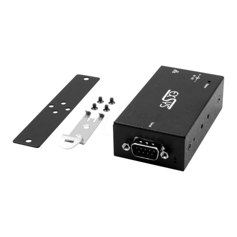
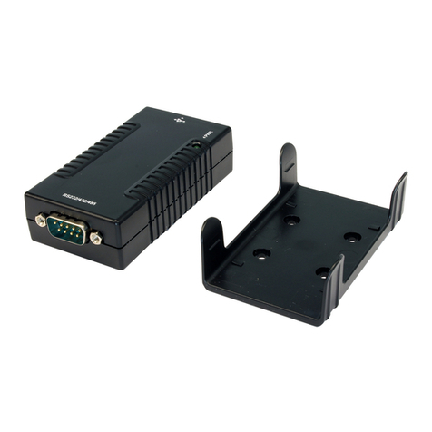
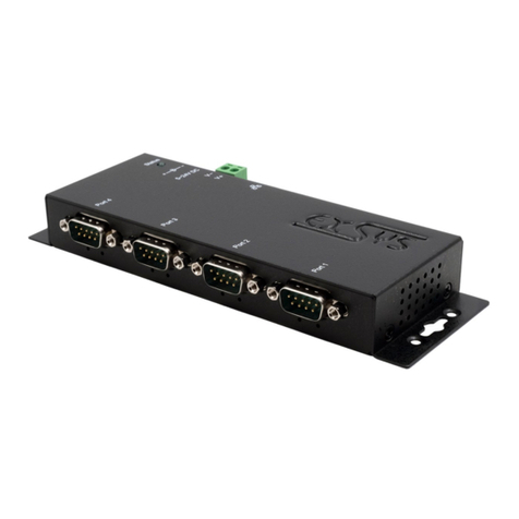
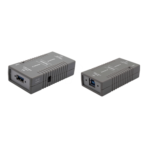
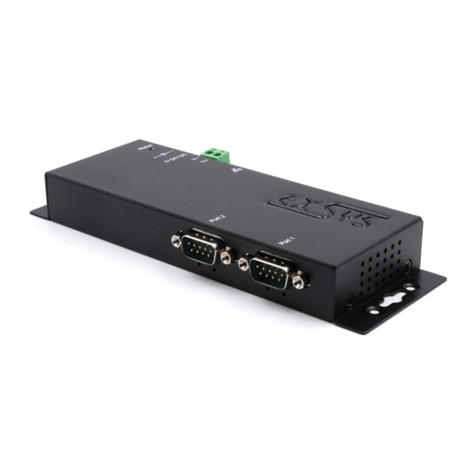
The modules are plug & play high-speed USB to Serial modules for USB 1.1 and 2.0
ports with up to 8 RS232 9Pin connectors. They provide 9Pin serial ports for serial
devices and 1 USB uplink port for PC. The USB to Serial modules design utilizes the
Chip-Set Prolific with 16C550 UART. It is not possible to change the address or IRQ
settings manually, they will be obtained automatically by the operating system.
DESCRIPTION & TECNICAL INFORMATION :
Compatibility: USB 1.1 & USB 2.0
Operating system: WIN 98/ME/2000/XP/Server 2003/Vista/Win7, Linux, MAC
Connectors: 9 pin RS-232 connector, 1 x B-Port, 1 x 5V connector
Extent of delivery: USB to Serial module, manual, CD, USB cable
Certificates: CE / FCC / RoHS / WEEE DE97424562
LAYOUT :
JUMPER SETTING & CONNECTORS:
HARDWARE INSTALLATION :
Beachten Sie bitte die folgenden Installationshinweise. Da es grosse Unterschiede bei
Computern gibt, können wir Ihnen nur eine generelle Anleitung zum Einbau der Module
geben. Bei Unklarheiten halten Sie sich bitte an die Bedienungsanleitung Ihres Computer-
systems.
1. Schliessen sie das mitgelieferte Kabel an der USB B Buchse des Moduls an.
2. Stecken sie jetzt gegebenenfalls den Stromanschluss des Netzteils (optional) an die
5Volt Buchse an und stecken sie den Netzstecker des Netzteils in eine Steckdose.
3. Verbinden sie nun das andere Ende (A-Stecker) des mitgelieferten Kabels mit der A-
Buchse an ihrem PC.
TREIBER INSTALLATION :
Windows 98/ME/XP/Server 2003&2008/Vista/7 (32&64-Bit):
Windows erkennt automatisch eine neue “USB Serial Device“. Legen Sie die Treiber CD
in Ihr CD-ROM Laufwerk ein (z.B. Laufwerk D:). Lassen sie nicht automatisch nach dem
Treiber suchen. Sondern öffnen sie folgenden Pfad auf der CD.
“D:\USB_to_IO\USB_to_Serial\(32_64bit)Win7_XP_Vista_2008_2003_98_ME”.
Starten sie nun die Datei „PL2303_Prolific_Driver Installer_V10626“ und folgen sie
den Anweisungen der Installations Software bis zum Ende. Starten sie jetzt den Rech-
ner neu. Nach dem Neustart wird das Modul automatisch von Windows erkannt und
installiert.
ÜBERPRÜFEN DES INSTALLIERTEN TREIBERS:
Klicken Sie auf Start< >Ausführen< geben sie “compmgmt.msc“ ein und klicken sie
auf >OK<. Wählen sie nun >GeräteManager<. Dort müssten Sie unter „Anschlüsse
(COM und LPT)“ neue Einträge z.B. „USB Serial Port (COM5)“ und unter
„Universeller Serielle Bus Controller“ den Eintrag „USB Serial Converter“ sehen.
Wenn Sie diese oder ähnliche Einträge sehen, sind die USB Module korrekt installiert.
REINIGUNG :
Zur Reinigung des Gerätes verwenden sie bitte ausschliesslich ein trockenes nicht
faserndes Tuch und entfernen sie die Verschmutzung mit leichtem Druck. Im Bereich
der Anschlüsse bitte darauf Achten dass keine Fasern des Tuchs in der Buchse verblei-
ben. Verwenden sie zu Reinigung in keinem Fall ein feuchtes oder nasses Tuch!
ATTENTION !!! Use only with optional original power supply !!!
5 Volt
DC :
TREIBER INSTALLATION :
INSTALLATION DER PERIPHERIEGERÄTE:
Die Seriellen Ports, der USB Module können nun auf die Maximale Baudrate von
115.2Kbaud eingestellt werden. Zum Beispiel mit Doppelklick den >USB Serial Port
(COM5)< öffnen. Hier können Sie z.B. Baudrate, Stoppbits usw. eintragen.
ÄNDERN DER COM ADRESSE (NICHT UNTER 98 & ME):
Öffnen sie den Gerätemanager, klicken sie z.B. auf >COM3< >Anschlusseinstellung<
und >Erweitert<. Sie können dann zwischen COM3 und 256 wählen!
Windows 2000:
Windows erkennt automatisch eine neue “USB Serial Device“. Legen Sie die Treiber CD
in Ihr CD-ROM Laufwerk ein (z.B. Laufwerk D:). Lassen sie nicht automatisch nach dem
Treiber suchen. Sondern öffnen sie folgenden Pfad auf der CD.
“D:\USB_to_IO\USB_to_Serial\Win2000”.
Starten sie nun die Datei „PL2303_DriverInstaller“ und folgen sie den Anweisungen
der Installations Software bis zum Ende. Starten sie jetzt den Rechner neu. Nach dem
Neustart wird das Modul automatisch von Windows erkannt und installiert.
ÜBERPRÜFEN DES INSTALLIERTEN TREIBERS:
Klicken Sie auf Start< >Ausführen< geben sie “compmgmt.msc“ ein und klicken sie
auf >OK<. Wählen sie nun >GeräteManager<. Dort müssten Sie unter „Anschlüsse
(COM und LPT)“ neue Einträge z.B. „USB Serial Port (COM5)“ und unter
„Universeller Serielle Bus Controller“ den Eintrag „USB Serial Converter“ sehen.
Wenn Sie diese oder ähnliche Einträge sehen, sind die USB Module korrekt installiert.
INSTALLATION DER PERIPHERIEGERÄTE:
Die Seriellen Ports, der USB Module können nun auf die Maximale Baudrate von
115.2Kbaud eingestellt werden. Zum Beispiel mit Doppelklick den >USB Serial Port
(COM5)< öffnen. Hier können Sie z.B. Baudrate, Stoppbits usw. eintragen.
ÄNDERN DER COM ADRESSE (NICHT UNTER 98 & ME):
Öffnen sie den Gerätemanager, klicken sie z.B. auf >COM3< >Anschlusseinstellung<
und >Erweitert<. Sie können dann zwischen COM3 und 256 wählen!
Linux:
Die Treiber befinden sich auf der Treiber CD im Verzeichnis:
“D:\USB_to_IO\USB_to_Serial\Linux
Sie werden unter den meisten Linux Versionen unterstützt. Da sich die einzelnen Versi-
onen von einander unterscheiden können wir ihnen leider hier keine Installationsanwei-
sung geben. Bitte halten sie sich an die Installationsanweisung für IO Ports ihrer Linux
Version.
MAC:
Die Treiber befinden sich auf der Treiber CD im Verzeichnis: .
“D:\USB_to_IO\USB_to_Serial\Mac_OS_X“ für MAC OS-X oder: .
“D:\USB_to_IO\USB_to_Serial\Mac_OS_9_8“ für Mac OS 9 & Mac OS 8
Sie werden unter den meisten MAC OS Versionen unterstützt. Da sich die einzelnen
Versionen von einander unterscheiden können wir ihnen leider hier keine Installations-
anweisung geben. Bitte halten sie sich an die Installationsanweisung für IO Ports ihrer
MAC OS Version.
DB 9M:
Pin Signal Pin Signal Pin Signal
1 CDC 4 DTR 7 RTS
2 RXD 5 GROUND 8 CTS
3 TXD 6 DSR 9 RI
Serial 9 Pin male connector:
USB B-Connector: USB 2.0 B-Connector:
Pin Signal Pin Signal
1 VCC 4 GND
2 DATA-
3 DATA+
Attention!
Never plug in with
force or in wrong
direction.
S1 9 Pin Serial
connector RS232
EX-1331 / 1S Serial
S2 9 Pin Serial
connector RS232
S1 9 Pin Serial
connector RS232
EX-1332 / 2S Serial
EX-1334 / 4S Serial EX-1338 / 8S Serial
S1 to S8 8 x 9 Pin
Serial connector RS232
S1 to S4 4 x 9 Pin
Serial connector RS232 5V Connector
USB B Connector
User Manual
User Manual
Vers. 3.1 / 08.03.11
Pin Signal Pin Signal Pin Signal
1 TXD 1 22 RXD 1 43 CTS 1
2 DTR 1 23 DSR 1 44 RTS 1
3 RXD 2 24 DCD 1 45 GND
Seriell 62 Pin SUB-D Buchse :
4 DSR 2 25 TXD 2 46 CTS 2
5 DCD 2 26 DTR 2 47 RTS 2
6 TXD 3 27 RXD 3 48 CTS 3
7 DTR 3 28 DSR 3 49 RTS 3
8 RXD 4 29 DCD 3 50 GND
9 DSR 4 30 TXD 4 51 CTS 4
10 DCD 4 31 DTR 4 52 RTS 4
11 RXD 5 32 GND 53 CTS 5
12 DSR 5 33 TXD 5 54 RTS 5
13 DCD 5 34 DTR 5 55 GND
14 TXD 6 35 RXD 6 56 CTS 6
15 DTR 6 36 DSR 6 57 RTS 6
16 RXD 7 37 DCD 6 58 GND
17 DSR 7 38 TXD 7 59 CTS 7
18 DCD 7 39 DTR 7 60 RTS 7
19 RXD 8 40 GND 61 CTS 8
20 DSR 8 41 TXD 8 62 RTS 8
21 DCD 8 42 DTR 8
DB62F:
JUMPER EINSTELLUNG & ANSCHLÜSSE:
