manuals.online logo
Brands
  1. Home
  2. •
  3. Brands
  4. •
  5. Extreme Canopy
  6. •
  7. Tent
  8. •
  9. Extreme Canopy CREST User manual

Extreme Canopy CREST User manual

WHAT YOU’LL NEED
Drill
Socket Set
Ladder
Mallet
Forklift / Crane / Scissor Lift *
Tape Measure
String-line
Level
Marking Pencil
Stanley Knife
Allen Key (supplied)
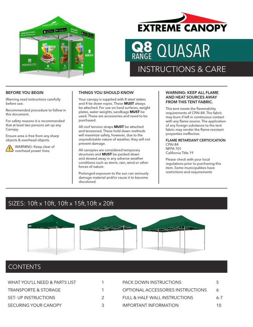
Warning read instructions carefully before use.
Recommended procedure to follow in this document.
For safety reasons it is recommended that four persons set up
any Crest Tent.
Ensure area is free from any sharp objects and overhead objects.
www.extremecanopy.com (888) 201 1968
CREST TENT OVERVIEW
1. Introduction
The Extreme Canopy Crest main structure is made up of extruded
aluminum and steel. The adjustable frame Base Plate can be used
on any ground surface.
Frame Specifications
Max Allowed Windspeed: 50mph (80km/hr)
Eave Connection: Hot-dip galvanized steel insert
Framework Material: Hard pressed extruded
aluminum 6061/T6 (13HW)
Cover Fabrics/Material
850gsm White or Colored PVC
950gsm Clear PVC
Wall Fabrics/Material
650gsm White PVC
50gsm Colored PVC
950gsm Clear PVC
All Materials are:
Waterproof
UV Protective
Flame Retardant (B1 DIN 4102/GB8642)
All seam/joins are constructed using high frequency welding
PLEASE NOTE
The Cross Wires indicated by the dotted
line are ONLY required for larger Spans.
2. Structure Description
www.extremecanopy.com (888) 201 1968
4. Part Description
Nr.
Description
Pcs.
Nr.
Description
Pcs.
1
Ridge connector
2
15
M10*70 Screw
16
2
Roof beam
4
16
M10*100 Screw
10
3
Corner connector
4
17
M10*120 Screw + Nut
4
4
Corner upright
4
18
Washer
12
5
Base plate
6
19
M16*30 Screw
12
6
Eave purlin
2
20
Steel stake
12
7
Reinforce beam
2
21
Weight bracket
6
8
Gable eave rail
4
22
Roof Fabric
1
9
Gable Support
2
23
Side Wall
2
10
Roof Purlin
3
24
Front wall/Back Wall
4
11
Tension Bolt
4
25
Triangle Fabric
2
12
Tension Bar
6
26
Pull rope
2
13
Connecting Rod
6
27
Roof bond
2
14
Mounting fork
1
28
Stake puller
1
5. Assembly Cautions
a) Before starting the construction, please measure the ground area in advance, and confirm the
tent’s dimension.
b) Tent may fix the base plate after assembling the whole frame.
c) A team of at least 5 experienced workers is necessary. Inexperienced people pls do not
assemble and dismantle the tent for avoiding the possible aftereffects. Pals read the instruction
manual carefully and check all parts before construction. Pls keep the kids away from the
working site.
d) Pls take the wind direction and nearby building into consideration when ground selection.
Different fixation solution for different ground condition (grass, flat ground, cement ground)
1. Expansion bolt: suitable for cement ground, fix each point with at least 2 nos.
2. Steel stake: suitable for earth and grass ground, fix each point with at least 2nos, and make
sure they drive to the bottom.
3. Ground mounting (base plate): suitable for all kinds of ground, each point has to be loaded
with at least 200 kg weight.
e) Safety inspection periodically.
3. Part Description
Item # Description
1 Ridge Connector
2 Roof Beam
3 Corner Connector (Type A / B)
4 Corner Upright
5 Base Plate (Type A / B)
6 Eave Purlin
7Reinforce Beam (A) / Cross Brace (B)
8 Gable Eave Rail
9 Gable Support
10 Roof Purlin
11 Tension Bolt
12 Tension Bar
13 Connecting Rod
14 Mounting Fork
Item # Description
15 M10 x 70 Screw
16 M10 x 100 Screw
17 M10 x 120 Screw + Nut
18 Washer
19 M16 x 30 Screw
20 Steel Stake
21 Weight Bracket
22 Roof Fabric
23 Side Wall
24 Front Wall/Back Wall
25 Triangle Fabric
26 Pull Rope
27 Roof Bond
28 Stake Puller
4. Part Description
Nr.
Description
Pcs.
Nr.
Description
Pcs.
1
Ridge connector
2
15
M10*70 Screw
16
2
Roof beam
4
16
M10*100 Screw
10
3
Corner connector
4
17
M10*120 Screw + Nut
4
4
Corner upright
4
18
Washer
12
5
Base plate
6
19
M16*30 Screw
12
6
Eave purlin
2
20
Steel stake
12
7
Reinforce beam
2
21
Weight bracket
6
8
Gable eave rail
4
22
Roof Fabric
1
9
Gable Support
2
23
Side Wall
2
10
Roof Purlin
3
24
Front wall/Back Wall
4
11
Tension Bolt
4
25
Triangle Fabric
2
12
Tension Bar
6
26
Pull rope
2
13
Connecting Rod
6
27
Roof bond
2
14
Mounting fork
1
28
Stake puller
1
5. Assembly Cautions
a) Before starting the construction, please measure the ground area in advance, and confirm the
tent’s dimension.
b) Tent may fix the base plate after assembling the whole frame.
c) A team of at least 5 experienced workers is necessary. Inexperienced people pls do not
assemble and dismantle the tent for avoiding the possible aftereffects. Pals read the instruction
manual carefully and check all parts before construction. Pls keep the kids away from the
working site.
d) Pls take the wind direction and nearby building into consideration when ground selection.
Different fixation solution for different ground condition (grass, flat ground, cement ground)
1. Expansion bolt: suitable for cement ground, fix each point with at least 2 nos.
2. Steel stake: suitable for earth and grass ground, fix each point with at least 2nos, and make
sure they drive to the bottom.
3. Ground mounting (base plate): suitable for all kinds of ground, each point has to be loaded
with at least 200 kg weight.
e) Safety inspection periodically.
A B
4. Part Description
Nr.
Description
Pcs.
Nr.
Description
Pcs.
1
Ridge connector
2
15
M10*70 Screw
16
2
Roof beam
4
16
M10*100 Screw
10
3
Corner connector
4
17
M10*120 Screw + Nut
4
4
Corner upright
4
18
Washer
12
5
Base plate
6
19
M16*30 Screw
12
6
Eave purlin
2
20
Steel stake
12
7
Reinforce beam
2
21
Weight bracket
6
8
Gable eave rail
4
22
Roof Fabric
1
9
Gable Support
2
23
Side Wall
2
10
Roof Purlin
3
24
Front wall/Back Wall
4
11
Tension Bolt
4
25
Triangle Fabric
2
12
Tension Bar
6
26
Pull rope
2
13
Connecting Rod
6
27
Roof bond
2
14
Mounting fork
1
28
Stake puller
1
5. Assembly Cautions
a) Before starting the construction, please measure the ground area in advance, and confirm the
tent’s dimension.
b) Tent may fix the base plate after assembling the whole frame.
c) A team of at least 5 experienced workers is necessary. Inexperienced people pls do not
assemble and dismantle the tent for avoiding the possible aftereffects. Pals read the instruction
manual carefully and check all parts before construction. Pls keep the kids away from the
working site.
d) Pls take the wind direction and nearby building into consideration when ground selection.
Different fixation solution for different ground condition (grass, flat ground, cement ground)
1. Expansion bolt: suitable for cement ground, fix each point with at least 2 nos.
2. Steel stake: suitable for earth and grass ground, fix each point with at least 2nos, and make
sure they drive to the bottom.
3. Ground mounting (base plate): suitable for all kinds of ground, each point has to be loaded
with at least 200 kg weight.
e) Safety inspection periodically.
A
A - Reinforcing Beam
B
B - Cross Brace
4. Part Description
Nr.
Description
Pcs.
Nr.
Description
Pcs.
1
Ridge connector
2
15
M10*70 Screw
16
2
Roof beam
4
16
M10*100 Screw
10
3
Corner connector
4
17
M10*120 Screw + Nut
4
4
Corner upright
4
18
Washer
12
5
Base plate
6
19
M16*30 Screw
12
6
Eave purlin
2
20
Steel stake
12
7
Reinforce beam
2
21
Weight bracket
6
8
Gable eave rail
4
22
Roof Fabric
1
9
Gable Support
2
23
Side Wall
2
10
Roof Purlin
3
24
Front wall/Back Wall
4
11
Tension Bolt
4
25
Triangle Fabric
2
12
Tension Bar
6
26
Pull rope
2
13
Connecting Rod
6
27
Roof bond
2
14
Mounting fork
1
28
Stake puller
1
5. Assembly Cautions
a) Before starting the construction, please measure the ground area in advance, and confirm the
tent’s dimension.
b) Tent may fix the base plate after assembling the whole frame.
c) A team of at least 5 experienced workers is necessary. Inexperienced people pls do not
assemble and dismantle the tent for avoiding the possible aftereffects. Pals read the instruction
manual carefully and check all parts before construction. Pls keep the kids away from the
working site.
d) Pls take the wind direction and nearby building into consideration when ground selection.
Different fixation solution for different ground condition (grass, flat ground, cement ground)
1. Expansion bolt: suitable for cement ground, fix each point with at least 2 nos.
2. Steel stake: suitable for earth and grass ground, fix each point with at least 2nos, and make
sure they drive to the bottom.
3. Ground mounting (base plate): suitable for all kinds of ground, each point has to be loaded
with at least 200 kg weight.
e) Safety inspection periodically.
www.extremecanopy.com (888) 201 1968
4. Assembly Cautions
a) Before commencing construction refer to the Ground Set Out
plan of the Crest Tent. Measure the ground area and confirm
the Tent dimensions.
b) Fix the Base Plate of the Crest Tent after assembling the
complete frame.
c) For safety reasons it is recommended that four persons
setup any Crest Tent. Read the instruction manual carefully
and check all parts before construction.
d) Check the wind and weather conditions before
commencing construction.
e) Ensure the area is free from any sharp objects and
overhead objects.
f) Ensure you have the correct ground fixings for your
application.
1. Grass: Steel Stakes
Fix each Base Plate with Steel Stakes. Ensure stakes are
appropriately secured into the soft surface (Grass/Dirt).
2. Cement: Dynabolt
Fix each Base Plate with Dynabolts.
3. Weight Plate: Ground Mounting (suitable for any surface)
Each Base Plate will need to have at least 440lbs.
g) Once constructed a safety inspection should be
conducted on a regular basis.
4.1 Dismantle Cautions
h) Mark and pack all components in appropriate product covers.
i) Ensure Roof and Walls Fabrics are completely dry before
packing down and fitting the protective covers. Do not put
heavy items on top of the Tent fabric during transport.
4.2 Maintenance
j) The PVC should be cleaned with mild detergent, do not use
any acidic or alcohol solutions. Only pack the PVC when it is
dried thoroughly, to prevent mold or stains.
k) Do not clean the aluminum parts by acid or high
concentrated cleanser.
l) Store in a cool, dry and clean environment and check
the goods regularly.
4.3 Product Cautions and Safety
m) When the Crest Tent is in use, do not leave it unattended.
n) Wind rating as per engineering certificate, review
weather conditions.
o) When the Crest Tent is in use and if part of the structure looks
damaged or not fit for purpose the Tent should be dismantled
at once for safety reasons.
www.extremecanopy.com (888) 201 1968
5. Construction
f) All ‘S’ serials tent are modular unit with 3 meters bay distance, which can extend unlimited.
6. Construction
Step 1: Assemble base plate (5) and corner
upright
Put the base plate into the corner upright as seen
drawing A. Fixed by a M10*120 screw.
Step 2: Assemble corner upright, corner
connector and roof beam
Put corner connector into corner upright and
roof beam, fixed by M10*70 screw.
Step 3: Assemble ridge connector with roof beams
Put ridge connector into two roof beams, fixed by M10*70 screws.
Step 4: Erect Frame
Erect the completed two frame constructions as
seen in drawing D, supported separately by two
team people in a certain distance.
Step 5: Assemble the Reinforce beam
Connect the two frame constructions by
reinforce beam(7) as shown in drawing E.
Fixed by M10*120 Screws(17).
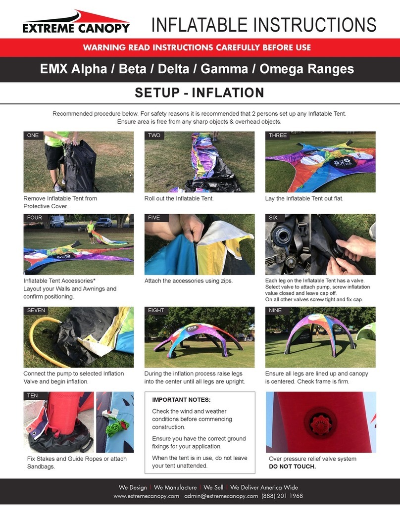
STEP 1:
Assemble Base Plate and Corner Upright
Position the Base Plate into the Corner Upright
and bolt together.
When commencing construction of the Crest Tent build each
frame bay section flat on the ground.
Refer to the Elevation Drawing and Parts List to confirm your
method of construction for Step 2.
FRAME TYPE A FRAME TYPE B
f) All ‘S’ serials tent are modular unit with 3 meters bay distance, which can extend unlimited.
6. Construction
Step 1: Assemble base plate (5) and corner
upright
Put the base plate into the corner upright as seen
drawing A. Fixed by a M10*120 screw.
Step 2: Assemble corner upright, corner
connector and roof beam
Put corner connector into corner upright and
roof beam, fixed by M10*70 screw.
Step 3: Assemble ridge connector with roof beams
Put ridge connector into two roof beams, fixed by M10*70 screws.
Step 4: Erect Frame
Erect the completed two frame constructions as
seen in drawing D, supported separately by two
team people in a certain distance.
Step 5: Assemble the Reinforce beam
Connect the two frame constructions by
reinforce beam(7) as shown in drawing E.
Fixed by M10*120 Screws(17).
STEP 2 (A):
Assemble Corner Upright,
Corner Connector and
Roof Beam
Put Corner Connector into
Corner Upright and Roof
Beam and bolt together.
STEP 2 (B):
Assemble Corner Upright and
Roof Beams
Insert Roof Beam into the
Upright Beam and bolt
together.
4. Part Description
Nr.
Description
Pcs.
Nr.
Description
Pcs.
1
Ridge connector
2
15
M10*70 Screw
16
2
Roof beam
4
16
M10*100 Screw
10
3
Corner connector
4
17
M10*120 Screw + Nut
4
4
Corner upright
4
18
Washer
12
5
Base plate
6
19
M16*30 Screw
12
6
Eave purlin
2
20
Steel stake
12
7
Reinforce beam
2
21
Weight bracket
6
8
Gable eave rail
4
22
Roof Fabric
1
9
Gable Support
2
23
Side Wall
2
10
Roof Purlin
3
24
Front wall/Back Wall
4
11
Tension Bolt
4
25
Triangle Fabric
2
12
Tension Bar
6
26
Pull rope
2
13
Connecting Rod
6
27
Roof bond
2
14
Mounting fork
1
28
Stake puller
1
5. Assembly Cautions
a) Before starting the construction, please measure the ground area in advance, and confirm the
tent’s dimension.
b) Tent may fix the base plate after assembling the whole frame.
c) A team of at least 5 experienced workers is necessary. Inexperienced people pls do not
assemble and dismantle the tent for avoiding the possible aftereffects. Pals read the instruction
manual carefully and check all parts before construction. Pls keep the kids away from the
working site.
d) Pls take the wind direction and nearby building into consideration when ground selection.
Different fixation solution for different ground condition (grass, flat ground, cement ground)
1. Expansion bolt: suitable for cement ground, fix each point with at least 2 nos.
2. Steel stake: suitable for earth and grass ground, fix each point with at least 2nos, and make
sure they drive to the bottom.
3. Ground mounting (base plate): suitable for all kinds of ground, each point has to be loaded
with at least 200 kg weight.
e) Safety inspection periodically.
A B
www.extremecanopy.com (888) 201 1968
f) All ‘S’ serials tent are modular unit with 3 meters bay distance, which can extend unlimited.
6. Construction
Step 1: Assemble base plate (5) and corner
upright
Put the base plate into the corner upright as seen
drawing A. Fixed by a M10*120 screw.
Step 2: Assemble corner upright, corner
connector and roof beam
Put corner connector into corner upright and
roof beam, fixed by M10*70 screw.
Step 3: Assemble ridge connector with roof beams
Put ridge connector into two roof beams, fixed by M10*70 screws.
Step 4: Erect Frame
Erect the completed two frame constructions as
seen in drawing D, supported separately by two
team people in a certain distance.
Step 5: Assemble the Reinforce beam
Connect the two frame constructions by
reinforce beam(7) as shown in drawing E.
Fixed by M10*120 Screws(17).
STEP 3:
Assemble Ridge Connector with Roof Beams
Put Ridge Connector into Roof Beam and bolt together.
You have now completed one Bay, repeat the process
until all Bays are constructed.
STEP 4:
Elevate Frame
When two bays have been completed, stand up the first bay.
Once upright hold into position with two team members or
secure with ropes. Stand up second bay and move into position.
Diagram note: (b) 3m or 5m bays, refer to elevation diagram.
f) All ‘S’ serials tent are modular unit with 3 meters bay distance, which can extend unlimited.
6. Construction
Step 1: Assemble base plate (5) and corner
upright
Put the base plate into the corner upright as seen
drawing A. Fixed by a M10*120 screw.
Step 2: Assemble corner upright, corner
connector and roof beam
Put corner connector into corner upright and
roof beam, fixed by M10*70 screw.
Step 3: Assemble ridge connector with roof beams
Put ridge connector into two roof beams, fixed by M10*70 screws.
Step 4: Erect Frame
Erect the completed two frame constructions as
seen in drawing D, supported separately by two
team people in a certain distance.
Step 5: Assemble the Reinforce beam
Connect the two frame constructions by
reinforce beam(7) as shown in drawing E.
Fixed by M10*120 Screws(17).
STEP 5 A:
Connect the
Reinforcing Beam
Connect the two bays
together using the
Frame Reinforcing
Beam and bolt
together.
STEP 5 B:
Connect the Cross Brace
Refer to elevation diagram
for positioning of Cross
Braces.
Fix the Cross Brace to the
Corner Uprights and bolt
together.
Cross
Brace
Refer to the Elevation Drawing and Parts List to confirm your
method of construction for Step 5.
www.extremecanopy.com (888) 201 1968
Step 6: Assemble eave purlin (6) and roof
purlin (10)
Insert the end of Eave purlin into the ‘D’ type
hook, and then hang up the other end of Eave
purlin by mounting hook. The installation of roof
purlin is same to Eave purlin.
Step 7: Assemble gable support (9) and
gable eave rail (8)
Insert the end of gable support into the ‘U’ type
hook of ridge connector, and fixed by screws;
Then hang up the hook end of gable eave rail
on the hook of gable support, the other end
installed on the corner support as seen in
drawing G. Same way for the other frame.
Step 8: Frame fixation (The frame must be fixed well prior to install fabric)
According to the ground condition, adjust the place of corner support, make it vertical, horizontal,
and then fix the base plate on the ground. (Select the fixation way accordingly as per different
ground condition)
Note: Fixation by expansion bolt (for cement ground), steel stake (for earth ground, grass ground)
and weight bracket (for various ground which can suffer a certain weight pressure).
8.1 Weight bracket fixation
Connect and fix the assembled corner upright (4)
with the weight bracket by using the M16*30 bolts
(19) and washers (18) as seen in drawing.
8.2 Fixation and dismantle of steel stakes
Insert steel stake (20) into the hole of base
plate (5) and drive them optimum to the ground
bottom by hammer. When dismantle, pls use
the stake puller (28) to pull it out
STEP 6:
Assemble Eave Purlin and Roof Purlin
Insert the end of Eave Purlin into the ‘D’ type hook on Roof
Beam and repeat on the other side.
Connect Roof Purlin into the ‘D’ type hook on Roof Beam
and repeat on the other end.
STEP 7:
Assemble Gable Support and Gable Eave Rail
Insert the end of Gable Support into the ‘U’ type hook of
Ridge Connector and fix with Screw.
Fit the ‘hook’ end of Gable Eave Rail on the ‘D’ type hook
of Gable Support.
Fit the other Gable Eave Rail to the ‘D’ type hook on the
Corner Connector.
Repeat this step for the other Gable End of the Tent.
Step 6: Assemble eave purlin (6) and roof
purlin (10)
Insert the end of Eave purlin into the ‘D’ type
hook, and then hang up the other end of Eave
purlin by mounting hook. The installation of roof
purlin is same to Eave purlin.
Step 7: Assemble gable support (9) and
gable eave rail (8)
Insert the end of gable support into the ‘U’ type
hook of ridge connector, and fixed by screws;
Then hang up the hook end of gable eave rail
on the hook of gable support, the other end
installed on the corner support as seen in
drawing G. Same way for the other frame.
Step 8: Frame fixation (The frame must be fixed well prior to install fabric)
According to the ground condition, adjust the place of corner support, make it vertical, horizontal,
and then fix the base plate on the ground. (Select the fixation way accordingly as per different
ground condition)
Note: Fixation by expansion bolt (for cement ground), steel stake (for earth ground, grass ground)
and weight bracket (for various ground which can suffer a certain weight pressure).
8.1 Weight bracket fixation
Connect and fix the assembled corner upright (4)
with the weight bracket by using the M16*30 bolts
(19) and washers (18) as seen in drawing.
8.2 Fixation and dismantle of steel stakes
Insert steel stake (20) into the hole of base
plate (5) and drive them optimum to the ground
bottom by hammer. When dismantle, pls use
the stake puller (28) to pull it out
Eave Purlin
Roof Purlin
Refer to the Elevation Drawing and Parts List to confirm your
method of construction for Step 6.
A - Eave Purlin Type B - Eave Purlin Type
Gable Support
Gable Eave Rail
www.extremecanopy.com (888) 201 1968
Step 6: Assemble eave purlin (6) and roof
purlin (10)
Insert the end of Eave purlin into the ‘D’ type
hook, and then hang up the other end of Eave
purlin by mounting hook. The installation of roof
purlin is same to Eave purlin.
Step 7: Assemble gable support (9) and
gable eave rail (8)
Insert the end of gable support into the ‘U’ type
hook of ridge connector, and fixed by screws;
Then hang up the hook end of gable eave rail
on the hook of gable support, the other end
installed on the corner support as seen in
drawing G. Same way for the other frame.
Step 8: Frame fixation (The frame must be fixed well prior to install fabric)
According to the ground condition, adjust the place of corner support, make it vertical, horizontal,
and then fix the base plate on the ground. (Select the fixation way accordingly as per different
ground condition)
Note: Fixation by expansion bolt (for cement ground), steel stake (for earth ground, grass ground)
and weight bracket (for various ground which can suffer a certain weight pressure).
8.1 Weight bracket fixation
Connect and fix the assembled corner upright (4)
with the weight bracket by using the M16*30 bolts
(19) and washers (18) as seen in drawing.
8.2 Fixation and dismantle of steel stakes
Insert steel stake (20) into the hole of base
plate (5) and drive them optimum to the ground
bottom by hammer. When dismantle, pls use
the stake puller (28) to pull it out
STEP 8:
Ground Fixings
The frame must be fixed and secure prior to installing the
Roof and Wall Fabric.
Ensure you have the correct ground fixings for your application.
1. Grass: Steel Stakes
Fix each Base Plate with Steel Stakes. Ensure stakes are
appropriately secured into the soft surface (Grass/Dirt).
2. Cement: Dynabolt
Fix each Base Plate with Dynabolts.
3. Weight Plate: Ground Mounting (suitable for any surface)
Each Base Plate will need to have at least 200kg.
8.1
Weight Plate Fixing
Fix the Corner Upright with the Weight Bracket using bolts
and washers as seen in the above drawing.
8.2
Securing Steel Stakes and removing Steel Stakes
Insert Steel Stake into the opening of Base Plate and drive Steel
Stake into the ground with a mallet/hammer until securely fixed.
When removing Steel Stakes use the Stake Puller to remove.
Pin Puller
www.extremecanopy.com (888) 201 1968
STEP 9:
Installation of Roof Fabric
Connect the Ropes to the Webbing on Roof Panel.
Insert right and left edges of the Roof Fabric into the
channels of the Roof Beam.
Pull the fabric into position using the Ropes.
Step 9:Fixation of roof fabric
Hook up the ring on the fabric by the special
towing ropes, and then insert both of the fabric
sides into the channel of roof beam, then pulling
the fabric to slide as seen in drawing H.
Step 10: Fix thread bracing (11) and
Tension bar (12)
Insert the Tension bar into the hole of the fabric
as shown in drawing I, install the thread
bracing properly, and put the fork of thread
bracing on the Tension bar, tighten the thread
bracing.
Step 11: Fixation of gable fabric(23) and side
walls fabric(24)
Insert the hook of fabric into the channel of gable
cross beam, then insert the left/right side of fabric
into the channel of uprights.
Step 12: Tent Inspection
Inspect the tent overall; Construction completed after approval of inspector.
7. Dismantling
a) After dismantling you have to clean the used fabric, wash the dirty mess. All the fabrics must be dry
before you start folding.
b) After dismantling you have to mark, sort and pack all the components immediately.
STEP 12:
Fix Thread Bracing and Tension Bar
Insert the Tension Bar into the sleeve of the Roof fabric the correct
way as shown in drawing (12a) .
Install the Thread Bracing Rod, then tighten the Thread Bracing
Rod evenly on both sides.
Drawing 12a.
Roof Tension Bar
Curve facing down.
www.extremecanopy.com (888) 201 1968
STEP 11:
Installing the Gable Fabric and Side Walls
Install the top of wall into channel of Cross Beam.
Insert the left/right side of fabric into the channel of uprights.
STEP 12:
Installing the Wall Tensions Bars
Side Tension Bars into bottom sleeve of Walls and
secure to uprights.
Product Cautions and Safety
When the Crest Tent is in use, do not leave your
marquee unattended.
Wind rating as per engineering certificate, review
weather conditions.
When the Crest Tent is in use and if part of the structure
looks damaged or not fit for purpose the marquee
should be dismantled at once for safety reasons.
Step 9:Fixation of roof fabric
Hook up the ring on the fabric by the special
towing ropes, and then insert both of the fabric
sides into the channel of roof beam, then pulling
the fabric to slide as seen in drawing H.
Step 10: Fix thread bracing (11) and
Tension bar (12)
Insert the Tension bar into the hole of the fabric
as shown in drawing I, install the thread
bracing properly, and put the fork of thread
bracing on the Tension bar, tighten the thread
bracing.
Step 11: Fixation of gable fabric(23) and side
walls fabric(24)
Insert the hook of fabric into the channel of gable
cross beam, then insert the left/right side of fabric
into the channel of uprights.
Step 12: Tent Inspection
Inspect the tent overall; Construction completed after approval of inspector.
7. Dismantling
a) After dismantling you have to clean the used fabric, wash the dirty mess. All the fabrics must be dry
before you start folding.
b) After dismantling you have to mark, sort and pack all the components immediately.
Wall Tension Bar
Rope Lacing (on inside of wall)
Wall Kedar

Other Extreme Canopy Tent manuals

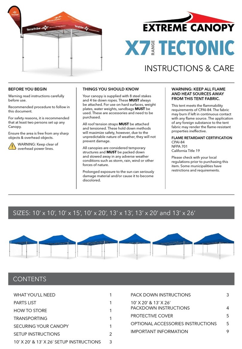
Extreme Canopy X7 RANGE TECTONIC User manual

Extreme Canopy

Extreme Canopy X7 RANGE TECTONIC User manual

Extreme Canopy X7 RANGE TECTONIC User manual

Extreme Canopy

Extreme Canopy X7 RANGE TECTONIC User manual

Extreme Canopy QUASAR Q8 Series User manual

Extreme Canopy

Extreme Canopy QUASAR Q8 Series User manual

Extreme Canopy EMX ALPHA User manual

Extreme Canopy

Extreme Canopy EMX ALPHA User manual

Extreme Canopy EMX Alpha Series User manual

Extreme Canopy

Extreme Canopy EMX Alpha Series User manual

Extreme Canopy QUASAR Q8 Series User manual

Extreme Canopy

Extreme Canopy QUASAR Q8 Series User manual

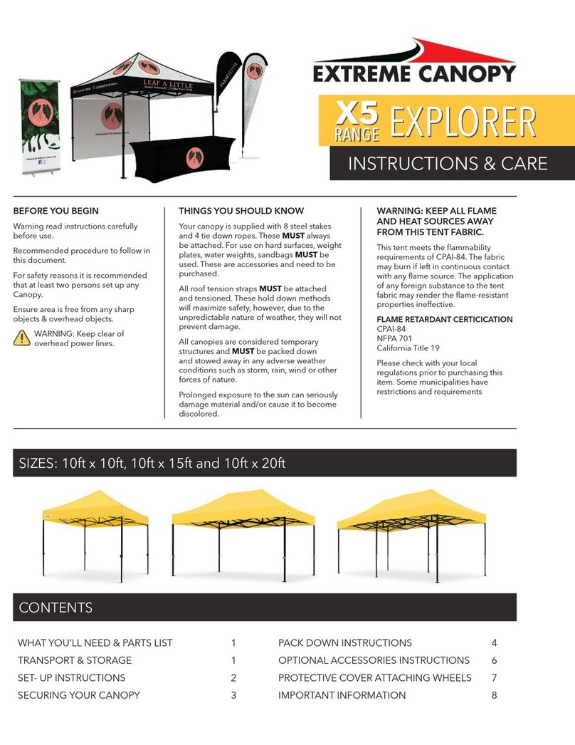
Extreme Canopy X5 RANGE User manual

Extreme Canopy

Extreme Canopy X5 RANGE User manual

Extreme Canopy EMX ALPHA User manual

Extreme Canopy

Extreme Canopy EMX ALPHA User manual

Extreme Canopy PAVILION User manual

Extreme Canopy

Extreme Canopy PAVILION User manual

Popular Tent manuals by other brands

Nordcap Easy Up 400 Build-up instructions

Nordcap

Nordcap Easy Up 400 Build-up instructions

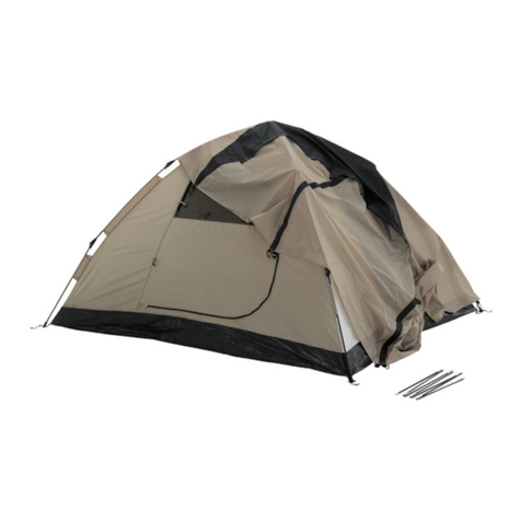
Zempire Neo Series instructions

Zempire

Zempire Neo Series instructions

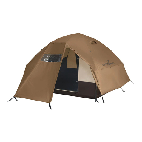
CampTrails Grand Manan Assembly instructions

CampTrails

CampTrails Grand Manan Assembly instructions

Maanta ULISSE 90 Instructions and warnings

Maanta

Maanta ULISSE 90 Instructions and warnings

OZTENT JV SIGNATURE EDITION owner's manual

OZTENT

OZTENT JV SIGNATURE EDITION owner's manual

GigaTent Summer Chalet Mini Tent owner's manual

GigaTent

GigaTent Summer Chalet Mini Tent owner's manual

Outsunny 84C-230 manual

Outsunny

Outsunny 84C-230 manual

Crivit Outdoor 96716 instruction manual

Crivit Outdoor

Crivit Outdoor 96716 instruction manual

Reimo Marina instructions

Reimo

Reimo Marina instructions

Outsunny 84C-063 Assembly instruction

Outsunny

Outsunny 84C-063 Assembly instruction

EuroTrail ATLANTIS PRO manual

EuroTrail

EuroTrail ATLANTIS PRO manual

TiiTENT TB300 manual

TiiTENT

TiiTENT TB300 manual

Coleman 2000033134 Assembly & instruction manual

Coleman

Coleman 2000033134 Assembly & instruction manual

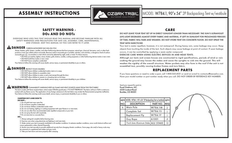
Ozark Trail W784.1 Assembly instructions and owner's manual

Ozark Trail

Ozark Trail W784.1 Assembly instructions and owner's manual

SlingFin CrossBow 2 instructions

SlingFin

SlingFin CrossBow 2 instructions

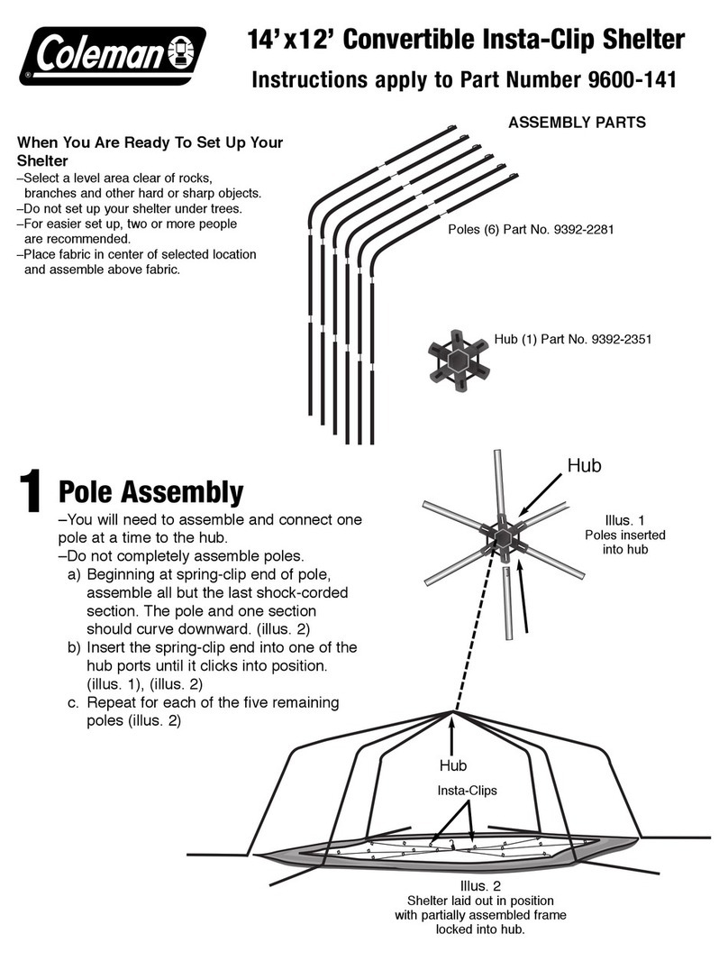
Coleman 9600-141 instructions

Coleman

Coleman 9600-141 instructions

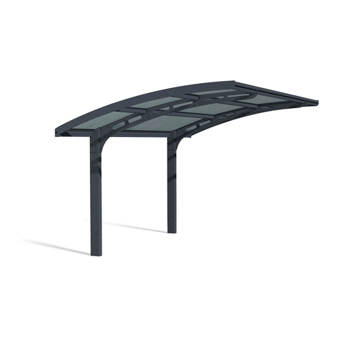
Palram Arizona 5000 Wave - WINGS manual

Palram

Palram Arizona 5000 Wave - WINGS manual

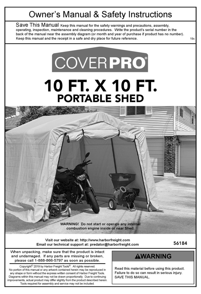
COVERPRO 56184 Owner's manual & safety instructions

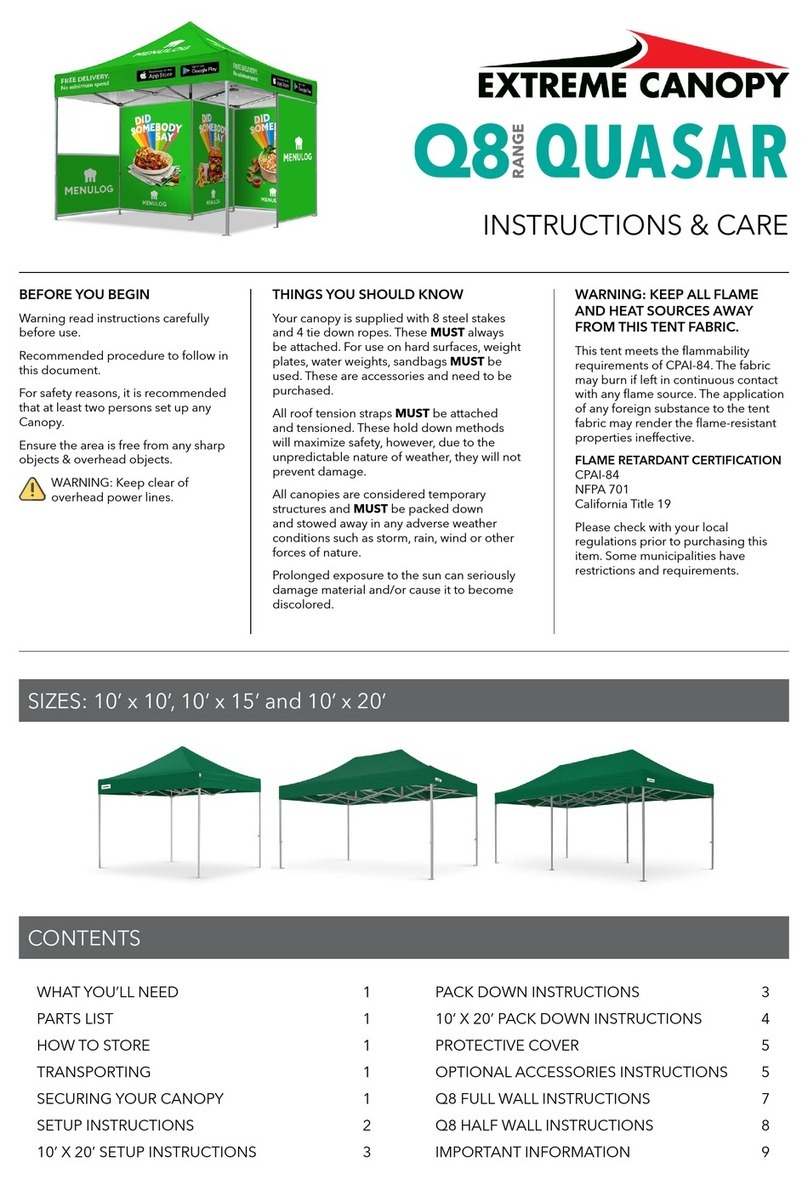
COVERPRO

COVERPRO 56184 Owner's manual & safety instructions

manuals.online logo
manuals.online logoBrands
  • About & Mission
  • Contact us
  • Privacy Policy
  • Terms and Conditions

Copyright 2025 Manuals.Online. All Rights Reserved.