Eyedro EH Series User manual

REV: L
PRODUCT GUIDE:
ELECTRICITY
MONITORING PRODUCTS

PRODUCT GUIDE: EYEDRO ELECTRICITY MONITORING PRODUCTS
©2011-2018 Eyedro Green Solutions Inc. Page | 2
CONTENTS
Introduction....................................................................................................................................................4
Overview....................................................................................................................................................4
Important Safety Information.....................................................................................................................5
Box Contents (By Product)............................................................................................................................7
Eyedro Home (EH*)...................................................................................................................................7
Eyedro Business (EB*)..............................................................................................................................8
Eyedro WiFi (EYEFI*)................................................................................................................................9
Hardware Installation ..................................................................................................................................10
Locating the Electrical Service ................................................................................................................10
Service Box and Distribution Panel .....................................................................................................10
Combination Service/Distribution Panel ..............................................................................................10
Install Current Sensors............................................................................................................................11
Materials You Will Need.......................................................................................................................11
Tools You Will Need ............................................................................................................................11
Procedure (Typical Service Entrance Monitoring)...............................................................................11
Procedure (Alternate Applications)......................................................................................................12
Measure Line Voltage (Optional – EH* and EB* products ONLY)..........................................................16
Materials You Will Need.......................................................................................................................16
Tools You Will Need ............................................................................................................................16
Procedure (Typical Residential Installation) ........................................................................................16
Align Wireless Modules (E*W* Products Only) .......................................................................................17
Mount Eyedro Device(s)..........................................................................................................................18
Materials You Will Need.......................................................................................................................18
Tools You Will Need ............................................................................................................................18
Procedure (Vertical Mount)..................................................................................................................18
Procedure (Horizontal Mount)..............................................................................................................19

PRODUCT GUIDE: EYEDRO ELECTRICITY MONITORING PRODUCTS
©2011-2018 Eyedro Green Solutions Inc. Page | 3
Connect Cabling......................................................................................................................................20
Materials You Will Need.......................................................................................................................20
Tools You Will Need ............................................................................................................................20
Procedure (Wired Installations - EH* and EB*) ...................................................................................20
Procedure (Wireless Installations - EHW* and EBW*)........................................................................21
Procedure (WiFi Installations - EYEFI*)...............................................................................................22
Internet Connection.....................................................................................................................................23
Provisioning Eyedro WiFi ........................................................................................................................24
Materials You Will Need.......................................................................................................................24
Tools You Will Need ............................................................................................................................24
Procedure (EYEFI*).............................................................................................................................24
Software Configuration................................................................................................................................25
MyEyedro.com.........................................................................................................................................25
Specifications..............................................................................................................................................26
Hardware Specifications..........................................................................................................................26
Sensor Specifications..............................................................................................................................27
Compliance .................................................................................................................................................29
Warranty......................................................................................................................................................30
Contact Information.....................................................................................................................................31
Appendix A: Troubleshooting......................................................................................................................32
No Power (all devices).............................................................................................................................33
No Communication – Part A Verify Internet Connectivity (wired and gateway devices).........................35
No Communication – Part B Verify Wireless Connectivity (wireless devices) ........................................39
Intermittent Communication/Measurements............................................................................................42
Unexpected Measurements.....................................................................................................................44

PRODUCT GUIDE: EYEDRO ELECTRICITY MONITORING PRODUCTS
©2011-2018 Eyedro Green Solutions Inc. Page | 4
INTRODUCTION
OVERVIEW
Eyedro Green Solutions Inc. is a software and electronics design company making electricity usage easy
to understand. We provide simple solutions for monitoring your electricity in real-time.
Combined with the MyEyedro cloud service, Eyedro is an affordable, easy to install and scalable
electricity monitor for your home and business. Join thousands of customers already using Eyedro to
keep an eye on their electricity use.
Thank you for choosing the Eyedro Electricity Monitoring System. You have taken the first step towards
better awareness of where your energy is being consumed. Awareness can lead to energy savings, cost
savings and peace of mind.
The Eyedro Electricity Monitoring System will help you keep an eye on your electrical consumption. Its
non-invasive design measures electrical current supplied to the building and computes the power
consumed. Data is stored on a remote server 24 hours a day - 7 days a week - 365 days a year. There is
no need to worry about losing your data or running out of storage space. Your data is available for review
from anywhere you have access to the internet - at home, at work or on the go! The easy to use interface
allows you to view your current and historical data, daily averages, bill to date and even predict what your
total bill will look like. Use the browser on your mobile phone to walk through your house switching
appliances on and off – you may be surprised what you learn!
The Eyedro Electricity Monitoring System will help you realize just how much electricity you are wasting
every day and how much money you could save by reducing that waste. You will soon realize that simple
changes in your habits – like turning off lights, unplugging unused equipment, or dialing back the
thermostat – will result in less consumption and more money in your pocket.
If you have any questions about using your Eyedro Electricity Monitoring System please visit
eyedro.com for information, documentation, videos and answers to frequently asked questions.

PRODUCT GUIDE: EYEDRO ELECTRICITY MONITORING PRODUCTS
©2011-2018 Eyedro Green Solutions Inc. Page | 5
IMPORTANT SAFETY INFORMATION
It is important that you observe some simple safety precautions when installing this product. The Eyedro
Electricity Monitor was designed to be non-intrusive and easy to install. Typically, there is no need to
disconnect any electrical cabling during the installation. However, there are a number of safety issues that
should be considered when installing and using the system.
Installation may require the cover of the main electrical panel to be removed while some wires
are still electrified. Even when the main breaker has been turned 'OFF' certain areas of the
panel may still be dangerous and carry the risk of shock, burn, and electrocution. Installation
should be performed by a qualified electrician. Check with your local authority having
jurisdiction for permit and inspection requirements. DO NOT attempt installation unless you know
where electrified areas within the panel are.
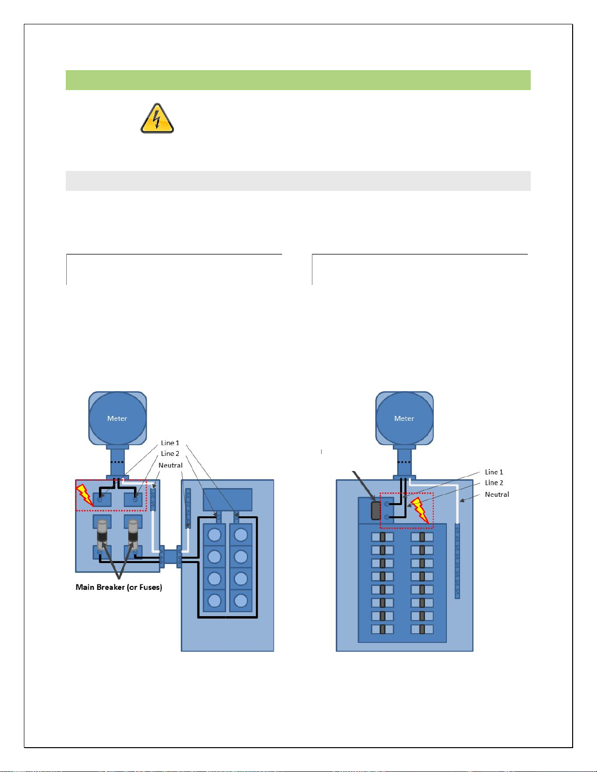
The current sensors clip on to the live service entrance cables which supply electricity to your electrical
panel. When installing these sensors:
DO NOT install the sensor onto a cable whose current exceeds the rated current of the sensor.
DO NOT install the sensor onto cabling that is loose, wet, or appears damaged (cracked, burned,
bare copper or missing insulation). Contact a qualified electrician and/or your electricity supplier
to report your findings.
DO NOT bend or force the service entrance cables during installation.
DO NOT force the sensor onto the cabling if the cable diameter appears to be too large.
The Eyedro Electricity Monitor (and all components) are designed for indoor use only and should be
installed inside a suitable building or panel. When installing:
DO NOT subject the unit or sensors to excessive temperature, humidity, force, shock, or dust
DO NOT use or store this product in locations that could adversely affect the product such as
rain, snow or desert.
DO NOT immerse the unit in water or other liquids. If liquid is spilled over it, remove power and
clean up the spill immediately with a soft, lint-free, cloth and allow all electronics to fully dry before
attempting to use.
DO NOT use this product where the use of radio frequency products can cause interference in
other critical control equipment (i.e. hospitals).
Please contact Eyedro Green Solutions Inc. if any component appears damaged or faulty.
DO NOT open the case of the unit or tamper with any of the internal components. This invalidates
the product warranty.
DO NOT attempt to repair the product by yourself.
DO NOT dispose of this product in your household waste. At the end of its serviceable life please
ensure product is disposed of according to local electrical and electronics equipment disposal
practices.

PRODUCT GUIDE: EYEDRO ELECTRICITY MONITORING PRODUCTS
©2011-2018 Eyedro Green Solutions Inc. Page | 6
The following notes apply to Eyedro Wireless products:
This equipment has been tested and found to comply with the limits for a Class A digital device, pursuant
to part 15 of the FCC Rules. These limits are designed to provide reasonable protection against harmful
interference in a residential installation. This equipment generates, uses and can radiate radio frequency
energy, and if not installed and used in accordance with the instructions, may cause harmful interference
to radio communications. However, there is no guarantee that interference will not occur in a particular
installation. If this equipment does cause harmful interference to radio or television reception, which can
be determined by turning the equipment off and on, the user is encouraged to try to correct the
interference by one or more of the following measures:
Reorient or relocate the receiving antenna.
Increase the separation between the equipment and receiver.
Connect the equipment into an outlet on a circuit different from that to which the receiver is connected.
Consult the dealer or an experienced radio/TV technician for help.
To satisfy FCC RF Exposure requirements for mobile and base station transmission devices, a separation
distance of 20 cm or more should be maintained between the antenna of this device and persons during
operation. To ensure compliance, operation at closer than this distance is not recommended. The
antenna(s) used for this transmitter must not be co-located or operating in conjunction with any other
antenna or transmitter.

PRODUCT GUIDE: EYEDRO ELECTRICITY MONITORING PRODUCTS
©2011-2018 Eyedro Green Solutions Inc. Page | 7
BOX CONTENTS (BY PRODUCT)
EYEDRO HOME (EH*)
A
B
C
D
Wired
(EHEM1)
Wireless
(EHWEM1)
Description
A
1
-
Eyedro Combo Module
-
1
Eyedro Sensor Module
-
1
Eyedro Gateway Module
B
2
2
Current Sensors (200A)
C
1
2
Low-voltage Power Adapter
D
10ft (3m)
3ft (0.9m)
Ethernet Cable

PRODUCT GUIDE: EYEDRO ELECTRICITY MONITORING PRODUCTS
©2011-2018 Eyedro Green Solutions Inc. Page | 8
EYEDRO BUSINESS (EB*)
A
B
C
D
Wired
(EBEM1)
Wireless
(EBW*)
Description
A
1
-
Eyedro Combo Module
-
1
Eyedro Sensor Module
-
11
Eyedro Gateway Module
B
3
1 - 32
Current Sensors (200A3)
C
1
2
Low-voltage Power Adapter
D
10ft (3m)
3ft (0.9m)1
Ethernet Cable
1 Gateway and Ethernet cable are not included in Wireless Expansion products (EBWXS*)
2 Sensors supported depend on model. EBEM1 = 3, EBWEM1 = 3, EBWXS3 = 3, EBWXS2 = 2, EBWXS1 = 1
3 200A (model ESCLV-25-200A) standard product. Substitutions available up to 3000A

PRODUCT GUIDE: EYEDRO ELECTRICITY MONITORING PRODUCTS
©2011-2018 Eyedro Green Solutions Inc. Page | 9
EYEDRO WIFI (EYEFI*)
A
B
C
Wireless
(EYEFI*)
Description
A
1
Eyedro EYEFI.* Module
B
1 – 41
Current Sensors (200A2)
C
1
Low-voltage Power Adapter
1 EYEFI.1=1, EYEFI.2=2, EYEFI.3=3, EYEFI.4=4
2 200A (model ESCLV-25-200A) standard product. Substitutions available from 5A to 3000A

PRODUCT GUIDE: EYEDRO ELECTRICITY MONITORING PRODUCTS
©2011-2018 Eyedro Green Solutions Inc. Page | 10
HARDWARE INSTALLATION
DO NOT CONTINUE WITH THE INSTALLATION OF THE EYEDRO
ELECTRICITY MONITORING SYSTEM UNTIL YOU HAVE READ THE
SAFETY SECTION OF THIS GUIDE.
LOCATING THE ELECTRICAL SERVICE
The electricity panel is typically located in the garage or utility room of the building – although this is not
always the case. The below diagrams show two typical 120/240V split-phase (single-phase) electrical
service configurations:
SERVICE BOX AND DISTRIBUTION
PANEL
In some cases the service entrance wires, from
the utility company, feed into a box that is
isolated from the distribution panel.
In this particular configuration, current sensors
can be installed on the Line wires in either the
service entrance panel or distribution panel.
COMBINATION
SERVICE/DISTRIBUTION PANEL
In some cases the service entrance wires, from
the utility company, and main breaker are
integrated into a single main electrical panel.
In this particular configuration, current sensors
are installed on the Line wires between the main
breaker and the meter.
Main Breaker

PRODUCT GUIDE: EYEDRO ELECTRICITY MONITORING PRODUCTS
©2011-2018 Eyedro Green Solutions Inc. Page | 11
INSTALL CURRENT SENSORS
MATERIALS YOU WILL NEED
Eyedro Current Sensors
Approved bushing or connector (not included)
Labels (optional – not included)
TOOLS YOU WILL NEED
•Flashlight •Screwdriver •Pliers
PROCEDURE (TYPICAL SERVICE ENTRANCE MONITORING)
Current sensors are installed on the individual line/live/hot wires only. This must be done inside the
electrical panel or junction box where the electrical connection is separated into the individual line, neutral
and ground wires.
Do not install sensors on neutral or ground conductors.
Do not install sensors on extension cords or sheathed/shielded cables.
Do not install sensors on conductors exceeding the max rating of the sensor.
1. Turn off the power by disengaging the main disconnect switch or turning off the main breaker.
CAUTION: EVEN WITH THE MAIN BREAKER IN THE 'OFF' POSITION, THE SERVICE
ENTRANCE WIRES WILL STILL BE ELECTRIFIED (BEFORE THE BREAKER). EXTREME
CAUTION SHOULD ALWAYS BE TAKEN WHILE WORKING AROUND ELECTRICITY.
2. Carefully remove panel cover(s) to expose service entrance wires.
3. Carefully remove a 'knockout' on the side of the panel and add an approved bushing or connector
to protect the wires that will pass through it.
4. Install one current sensor over each service entrance line/live wire.
a. Push the release clip in and open the sensor.
b. Carefully place the wire in the top of the sensor.
c. Carefully close the sensor ensuring sensor faces are aligned flush. A slight ‘click’ sound
is heard when the sensor is securely closed.
d. Ensure the sensor is installed in the correct orientation – sensor label side should face
the source (towards the service entrance) and sensor cable exit should face the load
(towards the circuit being monitored).
5. Optionally, use tape or other label to uniquely identify each sensor at the end of the wire nearest
the connector (i.e. "Sensor 1", "Phase A", etc.).
6. Route sensor cables through the bushing/connector so the plug ends are on the exterior of the
panel.
7. Once all sensors are installed correctly, replace panel cover(s).
8. Turn on the power.

PRODUCT GUIDE: EYEDRO ELECTRICITY MONITORING PRODUCTS
©2011-2018 Eyedro Green Solutions Inc. Page | 12
PROCEDURE (ALTERNATE APPLICATIONS)
The most common application of Eyedro Electricity Monitoring products is for monitoring of the electrical
service entrance of a building. However, there are other common applications where Eyedro Electricity
Monitoring products are often used. The following sub-sections provide brief overview of some of the
most common applications.
To use Eyedro Electricity Monitoring products in one of these applications, follow ALL instructions and
precautions from the Service Entrance installation procedure but substitute step 4 to install the sensors
on the line/live conductor of your desired circuit.
120V CIRCUIT MONITORING
120V circuits are typically used for lighting and receptacles throughout the building. These circuits
can be identified by a single-pole breaker in the electrical panel. Cabling typically consists of black
(line) and white (neutral) conductors with a bare copper (or green) ground conductor.
1 sensor is required for monitoring 120V circuits. The sensor should be installed on the line wire of
the circuit (typically black) and, if using Eyedro EH* or EB* products, voltage set to 120V (typical) in
the MyEyedro software.

PRODUCT GUIDE: EYEDRO ELECTRICITY MONITORING PRODUCTS
©2011-2018 Eyedro Green Solutions Inc. Page | 13
240V BALANCED CIRCUIT MONITORING
240V balanced circuits are typically used for large appliances throughout the building. Common
examples of 240V balanced loads are; electric heaters/baseboards, electric water heaters, air
conditioners, heat pumps, pool pumps, etc. These circuits can be identified by a double-pole breaker
in the electrical panel. Cabling typically consists of black (line 1) and red (line 2) conductors with a
bare copper (or green) ground conductor. Note: these circuits do not have white (neutral)
conductors.
1 sensor is required for monitoring 240V balanced circuits. The sensor should be installed on either
line wire of the circuit (typically black or red) and, if using Eyedro EH* or EB* products, voltage set to
240V (typical) in the MyEyedro software.

PRODUCT GUIDE: EYEDRO ELECTRICITY MONITORING PRODUCTS
©2011-2018 Eyedro Green Solutions Inc. Page | 14
240V UNBALANCED CIRCUIT MONITORING
240V unbalanced circuits are typically used for large appliances, split-receptacles and sub-panel
feeders throughout the building. A typical residential service entrance is also an example of a 240V
unbalanced circuit. These are circuits with both 120V and 240V components. Common examples of
240V unbalanced loads are; stoves, electric dryers, kitchen receptacles, sub-panels, etc. These
circuits can be identified by a double-pole breaker in the electrical panel. Cabling typically consists of
black (line 1), red (line 2), and white (neutral) conductors with a bare copper (or green) ground
conductor.
2 sensors are required for monitoring 240V unbalanced circuits. The sensors should be installed on
both line wires of the circuit (typically black and red) and, if using Eyedro EH* or EB* products,
voltage for each sensor set to 120V (typical) in the MyEyedro software.

PRODUCT GUIDE: EYEDRO ELECTRICITY MONITORING PRODUCTS
©2011-2018 Eyedro Green Solutions Inc. Page | 15
THREE-PHASE SERVICE OR BRANCH MONITORING (DELTA OR WYE)
Three-phase installations are common in commercial and industrial environments. These installations
require the use of Eyedro Business (EB*) or 3-port Eyedro WiFi (EYEFI.3) products.

PRODUCT GUIDE: EYEDRO ELECTRICITY MONITORING PRODUCTS
©2011-2018 Eyedro Green Solutions Inc. Page | 16
MEASURE LINE VOLTAGE (OPTIONAL – EH* AND EB* PRODUCTS ONLY)
MATERIALS YOU WILL NEED
None
TOOLS YOU WILL NEED
•Voltmeter or Multimeter
PROCEDURE (TYPICAL RESIDENTIAL INSTALLATION)
CAUTION: Extreme caution should always be taken while working around electricity.
Do not attempt this measurement without the proper tools and safeguards.
1. Locate an electrical receptacle as close to the current sensors as possible.
There is often a receptacle in the same room as the electrical panel.
2. Set the multimeter to AC voltage. The markings may appear as VAC, AC V, or a V beneath a sine
wave.
3. Choose the AC voltage range closest to the voltage you will measure. Typical voltage in North
American homes and businesses is between 110 to 120 volts.
Some circuits used for large equipment such as dryers, air conditioners, electric stoves
and ovens may use voltage in the range of 220 to 240 volts. These instructions do not
cover the methods used to measure a 220V outlet or three phase circuits.
4. Place one probe into each of the two slot terminals of the electrical receptacle. The voltage will be
displayed on the meter.
Grasp the meter probes by the insulation - NEVER touch the metal probes during testing.
5. The voltage should typically measure in the range of 106 to 126 volts for most circuits. Record
this value for later use while configuring your device in the software service.
6. Carefully remove the probes, being careful not to touch the metal part of the probes to anything or
each other.

PRODUCT GUIDE: EYEDRO ELECTRICITY MONITORING PRODUCTS
©2011-2018 Eyedro Green Solutions Inc. Page | 17
ALIGN WIRELESS MODULES (E*W* PRODUCTS ONLY)
Eyedro Wireless Electricity Monitoring (E*W*) products have all the same features as the non-wireless
version but do not require a network connection near the point where the sensors are installed. The
modules will communicate with each other over their own private wireless network so that the sensors
can be installed where you need them and the gateway module can be located near an available RJ45
network connection
E*W* products operate on a custom wireless protocol operating on the 2.4GHz frequency band.
Operating range varies for each installation depending on distance between and the number (and
material) of obstructions the wireless communication must pass through. Typical distances of 1000ft
(300m) can be expected.
To achieve best performance in wireless installations the following guidelines should be followed:
1. Minimize the number of obstructions between modules where possible (interior/exterior walls,
floors, windows, trees, etc). Line of sight provides best performance.
2. Minimize the number of 2.4GHz radiators in close proximity to the modules (WiFi routers, WiFi
devices, Bluetooth devices, microwaves, ZigBee/IEEE 802.15.4 wireless devices).
3. If using a WiFi bridge device for connectivity, create a physical separation (>24”) between Eyedro
module(s) and WiFi bridge. If possible, plug the two devices into separate receptacles.
4. Modules should be secured in position with screws, velcro tape or by other means. They should
not be left hanging off of wires because if they are bumped it can affect the signal quality.
5. Keep the area around the Eyedro module free from metallic objects.
6. Do not lay the Eyedro module on the metal electrical panel - if unavoidable, put an insulating
material, like wood or foam, between the Eyedro module and the metal.
7. Do not seal in the panel or other metal enclosure.
8. Try to ensure that the modules are positioned in the best possible orientation as shown in the
picture below.

PRODUCT GUIDE: EYEDRO ELECTRICITY MONITORING PRODUCTS
©2011-2018 Eyedro Green Solutions Inc. Page | 18
MOUNT EYEDRO DEVICE(S)
MATERIALS YOU WILL NEED
Two(2) #6 mounting screws (optional – not included)
Double-sided tape (optional – not included)
TOOLS YOU WILL NEED
•Screwdriver
PROCEDURE (VERTICAL MOUNT)
1. Write down the 8-digit serial number from the back of the module. This will be required during
software setup.
The serial number will be in the format "123 - 45678"
2. Find a clear area on the wall beside the electrical panel (or router in the case this is the Eyedro
Wireless Gateway Module).
Make sure all cables will easily reach the module before securing.
3. Secure the module using either:
a) Screws (recommended method)
i. Mark locations on the wall for the screws using the module or template below as
a reference.
ii. Drive the two(2) #6 screws into wall surface leaving ~0.125in (3mm) exposed.
iii. Align keyholes on back of module with mounting screws.
iv. Carefully push module over screws and slide down to secure in place.
v. Ensure secure fit.
b) Double-sided tape
i. Cut several pieces of double-sided tape and place on back of module.
ii. Peel tape backing off.
iii. Press module carefully but firmly against surface to be mounted on.
iv. Hold in place as per tape instructions.
v. Ensure module is held securely in place.

PRODUCT GUIDE: EYEDRO ELECTRICITY MONITORING PRODUCTS
©2011-2018 Eyedro Green Solutions Inc. Page | 19
Mounting Wall Template (1:1 Scale)
PROCEDURE (HORIZONTAL MOUNT)
Mounting is not required for horizontal installations (i.e. on a desktop or shelf). If added security is
desired, follow instructions for vertical mounting using screws or double-sided tape.

PRODUCT GUIDE: EYEDRO ELECTRICITY MONITORING PRODUCTS
©2011-2018 Eyedro Green Solutions Inc. Page | 20
CONNECT CABLING
MATERIALS YOU WILL NEED
Ethernet cable
Low-voltage power adapter(s)
Tie wraps (optional – not included)
TOOLS YOU WILL NEED
•None
PROCEDURE (WIRED INSTALLATIONS - EH* AND EB*)
1. Connect sensor cables to the Eyedro module.
Never force connectors or apply levering action.
2. Connect one end of Ethernet cable to Eyedro module.
Ensure retention clip on the cable is intact and connector is securely mated.
3. Connect the other end of the Ethernet cable to the router (or Internet access point).
Ensure retention clip on the cable is intact and connector is securely mated.
4. Connect the appropriate end of the low-voltage power adapter to the Eyedro module.
Never force connectors or apply levering action.
5. Plug the other end of the low-voltage power adapter into a nearby AC wall receptacle.
6. Secure all wiring neatly with tie wraps.
This manual suits for next models
6
Table of contents
Other Eyedro Measuring Instrument manuals

Eyedro
Eyedro E5B-EW-E3 User manual

Eyedro
Eyedro E5B-M-T2 User manual

Eyedro
Eyedro EYEDRO-HOME User manual

Eyedro
Eyedro E5B-M-E3 User manual

Eyedro
Eyedro EBEM1 User manual

Eyedro
Eyedro E5B-M-GWE3 User manual

Eyedro
Eyedro EHWEM1 User manual

Eyedro
Eyedro E5B-M-GWE3 User manual

Eyedro
Eyedro E5B-M-P2 User manual