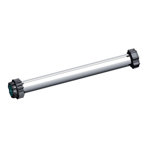
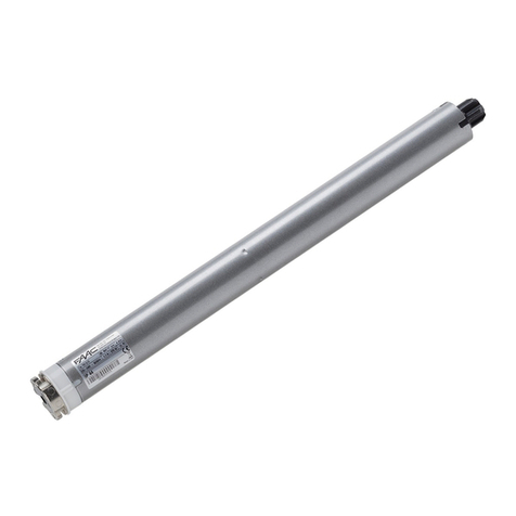
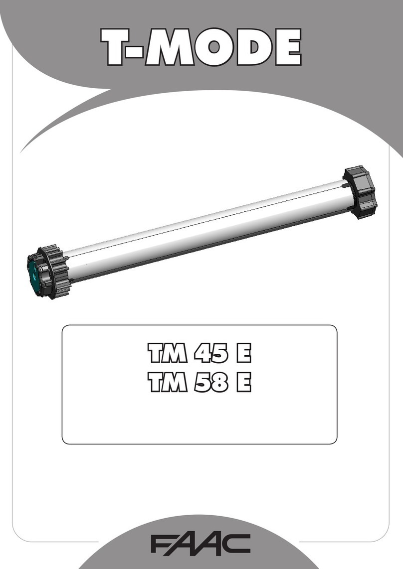
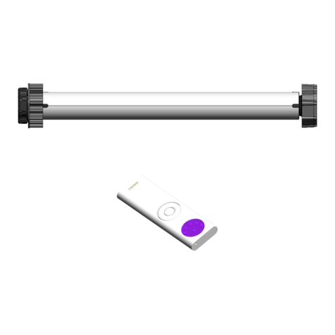
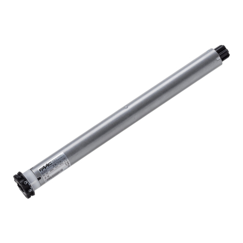
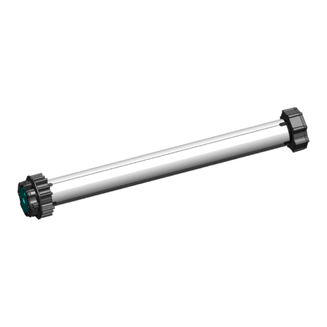
FAAC T-MODE TM 35 ER User manual

T-MODE
TM 35 ER - TM35 ERO
TM 45 ER - TM 58 ER

ENGLISH
2
WARNINGS FOR THE INSTALLER
DECLARATION OF CONFORMITY
Manufacturer: FAAC S.p.A.
Address: Via Calari, 1 - 40069 Zola Predosa BOLOGNA - ITALY
Declares that: Operator mod. TM 35 ER , TM35 ERO, TM 45 ER , TM 58 ER
• conformstotheessentialrequirementsofthefollowingEECdirectives:
-2006/95/EEC
- 2004/108/EEC
-99/05/EEC
•itthusconformstothefollowingharmonisedstandards:
-EN60335-1-95,EN60335-2-97/10-2000.
-EN61000-3-2,EN61000-3-3,
-EN55014-1,EN55014-2
Bologna,Bologna,,01/10/2012 TheManagingDirector
A. Marcellan
1. ATTENTION! To ensure the safety of people, it is important that
you read all the following instructions. Incorrect installation or
incorrect use of the product could cause serious harm to people.
Keep these instructions for future reference.
2. Carefully read the instructions before beginning to install the
product.
3. This product was designed and manufactured exclusively for
thepurposeindicatedinthisdocumentation.Anyotheruse,not
expresslyindicatedhere,couldcompromisethegoodcondition/
operationoftheproductand/orbeasourceofdanger.
4. FAACdeclinesanyresponsibilityforimproperuseoruseotherthan
thatforwhichtheautomatedsystemwasintended.
5. Disconnect the power supply before any operation on the
system.
6. Theinstallationmustbecarriedoutbyqualifiedtechnicalpersonnel
inconformitywiththenormsinforce.
7. Thepowermainsoftheautomatedsystemmustbefittedwitha
multi-polepowerswitchwithaswitch-contactgapofatleast3
mm.
8. Themin.installationheightfortheautomatedsystemis2.5m.
9. Makesurethatadifferentialswitchwithtripthresholdof0.03A
isfittedupstreamofthesystem.
10. Severalmotorscanbeconnectedwiththesameinverterifthe
lattersupportsthepowerneededbythemotors.
11. Twoinverterscanbeconnectedwiththesamemotorpaying
attention that a few motor parameters could be changed
pressing simultaneously the up/down button on different
inverters.
12. UseonlyFAACoriginalpartsformaintenance.
13. Theequipmenthandlingmustalwaysbeatsight.
14. Donotallowchildrenoradultstostayneartheproductwhile
itisoperating.
15. Keepradiocontrolsorotherpulsegeneratorsoutofreachof
children,topreventtheautomatedsystemfrombeingactivated
unintentionally.
16. The automated system cannot be repaired/adjusted by the
end-user;theseoperationscanonlybecarriedoutbyqualified
personnel.
17. Anything not expressly specified in these instructions is not
permitted.
18. The setting of the travel stops must be made with the motor installed
inside the tube (not at the bench).
19. The obstacle detection while lowering is active only if the suitable
accessoryisinstalledonthemotor.
20. Theequipmentisnotintendedtobeusedbypeople(childrenincluded)
withoutsufficientexperienceorknowledge,unlesstheyaresurveilledor
instructedontheequipmentusebyapersonresponsibleforthesafety.
21. Children must be supervised to make sure they do not play with the
equipment.
22. IncaseofoutdoorinstallationinstallthedesignatedcableH05RR-Fwitha
min.carbonpercentageof2%andamin.sectionof4x0.75mm².
23. Intheversionwithradiocontroltheinstallationofthestepbuttonforthe
manualoperationincaseofradiocontrolproblemsismandatory.

a
b
c
ed
f
L
ENGLISH
3
2 TECHNICAL SPECIFICATIONS
T-MODE
35ER
/ERO
MODEL
TORQUE
(Nm)
FREQUENCY
OFUSE
MAX.
USETIME
(min-
utes)
SPEED
(Rpm)
VOLTAGE
(V)
FREQUENCY
(Hz)
POWER
(W)
CURRENT
(A)
MOTOR
SHAFTMAX.
ROTATIONS
MOTOR
DIAMETER
(mm)
“L”LENGTHWITH
ADAPTER(mm)
PROTECTION
CLASS
5/28 520% 4 28 230 50 150 0.68 50 35 540 IP44
10/14 10 20% 4 14 230 50 140 0.66 50 35 540 IP44
13/14 13 20% 4 14 230 50 170 0.78 50 35 540 IP44
Fig.1
1 DESCRIPTION
T-MODE
45ER
MODEL
TORQUE
(Nm)
FREQUENCY
OFUSE
MAX.
USETIME
(min.)
SPEED
(Rpm)
VOLTAGE
(V)
FREQUENCY
(Hz)
POWER
(W)
CURRENT
(A)
MOTOR
SHAFTMAX.
ROTATIONS
MOTOR
DIAMETER
(mm)
“L”LENGTHWITH
ADAPTER(mm)
PROTECTION
CLASS
8/17 820% 417 230 50 130 0.6 50 45 440 IP44
15/17 15 20% 417 230 50 180 0.8 50 45 465 IP44
20/17 20 20% 417 230 50 230 1 50 45 480 IP44
30/17 30 20% 417 230 50 250 1.3 50 45 500 IP44
35/12 35 20% 4 12 230 50 250 1.2 50 45 500 IP44
45/12 45 20% 4 12 230 50 270 1.4 50 45 500 IP44
50/12 50 20% 4 12 230 50 300 1.4 50 45 500 IP44
T-MODE TUBULAR MOTORS WITH RADIO ELECTRONIC TRAVEL
LIMITS
USING THE MECHANICAL SENSOR FOR OBSTACLE DETECTION, THE “L” LENGTH OF THE MOTOR WITH THE ADAPTER INCREASES BY
41 mm ( L + 41 mm )
aTubularmotor
bExampleofwheeladapter.
(Accessory)
cExampleofcrownadapter.
(Accessory)
dTravellimitringnut
eExampleofmotorsupport
(Accessory)
fMechanicalsensorfor
obstacledetection
(Accessory)

a
c
b A
aA = ..x.. mm
A = ..x.. mm
Ø 3 mm
b
b
4X10
a
c
b
a
b
ENGLISH
4
MODEL
T-MODE
58ER
TORQUE
(Nm)
FREQUENCY
OFUSE
MAX.
TIME
OFUSE
(min.)
SPEED
(Rpm)
VOLTAGE
(V)
FREQUENCY
(Hz)
POWER
(W)
CURRENT
(A)
MOTOR
SHAFTMAX.
ROTATIONS
MOTOR
DIAMETER
(mm)
“L”LENGTHWITH
ADAPTER
(mm)
PROTECTION
CLASS
70/12 70 20% 4 12 230 50 310 1.4 50 45 540 IP44
80/12 80 20% 4 12 230 50 320 1.5 50 45 540 IP44
100/12 100 20% 413 230 50 410 1.9 50 45 550 IP44
120/12 120 20% 413 230 50 450 2.1 50 45 550 IP44
Fig.2
Fig.3
Fig.4
Fig.5
3 INSTALLATION
3.1 ASSEMBLING THE TUBULAR MOTOR
1)Fitthecrownadapter(Fig.2ref.a)inthetubularmotor,
until it is completely inserted in the guide on the travel
limitringnut.
2)Fitthewheeladapter(Fig.2ref.b)inthemotorshaft.If,
intheapplicationforrollingshutters,theobstacledetection
duringloweringisrequired,fitthemechanicalsensorfor
obstacledetectionbeforefittingthewheeladapter(fig.2
ref.bA).(alreadybuilt-ininmodelTM35ERO)
3)Locktheadapterwiththesuppliedstop.(Fig.2ref.c)
4)Makesurethattheadapteriswellsecured(Fig.2 ref.
c)
3.2 INSTALLING THE TUBULAR MOTOR
1)MeasuredimensionAonthetubularmotor,asshown
infigure3ref.a.
2)DrillaholewithadrillØ3mmontheroller(Fig.3ref.
b)atthedistanceA,previouslymeasuredonthetubular
motor(Fig.3ref.a).
3)Fittheassembledtubularmotorinsidetherollerfrom
the side opposite the cap, until the crown adapter is
completelyinsidetheroller(Fig.4ref.a).
4)Securethewheeladaptertotherollerwithatapping
screw4x10fittedinthepreviouslydrilledhole,asshown
infigure4ref.b.
5)Installthepreviouslychosenmotorsupportfromtheside
oftheelectricfacility(Fig5refa).
6)Fitthemotor-drivenrollerinthemotorsupport(Fig.5ref.
b),andonthecapsupport(Fig.5ref.c).
7)Checkwithalevelifthemotor-drivenrollerisperfectly
horizontal;ifnecessary,modifytheheightofthemotoror
capsupports.
ELECTRICFACILITYSIDE

OK
LN
230 V ~
*
230 V ~
LN
L
A
A
OK
ENGLISH
5
3.3 ELECTRIC CONNECTIONS
1) Cut power supply before attempting any job on the system.
2) Install an omnipolar switch with contact opening distance of 3 mm or greater on the power supply mains of
the automated system.
3) Wire the cables according to the diagram; if the motor rotates in the opposite direction, do not reverse the
black and brown wires, as at the end of the set-up, the up or down push-buttons are automatically matched
to the correct direction of motor rotation.
Fig.6
*ATTENTION: IF A PUSH-BUTTON
COMMAND IS NOT USED, DO NOT
CONNECT THE BLACK WIRE.
ATTENTION:thepush-buttonhasastep-by-steplogicwithdead-mancontrol.Everytimethepush-buttonispressed,
animpulseissenttothemotor(EXAMPLE:FIRSTPRESSINGHELDOFTHEPUSH-BUTTON:UP;PUSH-BUTTONRELEASE:STOP;
SECONDPRESSINGHELD;DOWNetc.)
3.3.1 MOTOR OPERATED BY REMOTE CONTROL ONLY
3.3.2 MOTOR OPERATED BY REMOTE CONTROL AND PUSH-BUTTON
BROWN
BROWN
BLUE
BROWN
BLUE
YELLOW-GREEN
YELLOW-GREEN
Fig.7
RED OR
BLACK
RED OR
BLACK
RED OR
BLACK

X 1
X 1 P
X 1
X 2
P
ON
P
ENGLISH
6
4 MEMORY STORING THE FIRST RADIO
UP
DOWN
STOP /
PREFERRED POSITION
PROGRAMMING
PUSH-BUTTON
1)Supplypowertothemotor.
2)Themotorperformsabriefmovementinbothdirectiontoconfirmthememoryisempty.
3)Within10seconds,presstheprogrammingpush-button“P”for2secondsandwithinthefollowing10seconds,press
thestop/preferredpositionpush-button.
4)Themotorperformstwobriefmovementsinbothdirectionstoconfirmtheperformedmemorystoring.
WITHIN10SECONDS
2 seconds
1) DURING THE MEMORY STORING PHASE OF THE FIRST REMOTE CONTROL AND TILL THE END OF
THE SET-UP PROCEDURE, THE MOTOR OPERATES IN DEAD-MAN MODE. (PUSH-BUTTON HELD DOWN)
2) BEFORE COMPLETING THE SET-UP, THE MOTOR COULD ROTATE IN THE OPPOSITE DIRECTION TO THE GIVEN COMMAND (E.G.: YOU
PRESS THE UP PUSH-BUTTON AND THE ROLLING SHUTTER LOWERS); AT THE END OF THE SET-UP, THE UP OR DOWN PUSH-BUTTONS
ARE AUTOMATICALLY MATCHED TO THE CORRECT DIRECTION OF ROTATION.
Fig.8
Fig.9
WITHIN10SECONDS
5 SET-UP (SETTING THE TRAVEL LIMITS)
The SET-UP procedure enables you to set, by pressing the connected push-buttons, the up and down travel limit
and the correct functions for the rolling shutter to be motorised (ROLLING SHUTTER MODE, STANDARD AWNING MODE
AND CASSETTE AWNING MODE).
TheSET-UPprocedurecanonlyoccurinAUTOMATICmode(withtwomodes)orinMANUALmode.
TheAUTOMATIC SET-UPispossibleforrollingshuttersonly,
TheMANUAL SET-UP ispossibleforallapplications(ROLLINGSHUTTER,STANDARDAWNINGORCASSETTEAWNING).
2 seconds
REAR
VIEW
MAX. 20 RADIO DEVICES CAN BE STORED IN THE MEMORY OF THE MOTOR INTERNAL RECEIVER (WALL-MOUNTED REMOTE CONTROLS,
RADIO ANEMOMETERS, ETC.). MEMORY STORING CAN OCCUR IN ANY MOTOR STATUS.
IF THE SUN SENSOR IS ENABLED ON THE MOTOR, THE COMMANDS SENT BY ANY ALREADY MEMORY-STORED REMOTE CONTROL ARE
INHIBITED; DISABLE FIRST THE SUN SENSOR USING THE REMOTE CONTROL.
Portable remote control
Wall-mounted remote control
CHANGE RADIO
CHANNEL
ENABLE
DISABLE
SUN SENSOR

ab
ENGLISH
7
PROGRAMMING
PUSH-BUTTON
5.2 SET-UP FOR ROLLING SHUTTERS
The automatic set-up can only be executed if the motor is installed on rolling shutters with an upper mechanical
stop (e.g.: rising travel limit plugs Fig.10 ref. b) and with the mechanical sensor for obstacle detection (Fig.10 ref.
a) or motor model TM35 ERO.Ifthisprocedureisperformed,themotorsetsalltravellimitsautomatically.
5.1 FUNCTIONS SET WHEN THE APPLICATION TYPE IS DEFINED IN THE SET-UP MODE
MECHANICAL
SENSOR
FOR OBSTACLE
DETECTION
UPPER
MECHANICAL
STOP
Fig.10
WHEN THE AUTOMATIC SET-UP IS PERFORMED, THE MOTOR SETS IN THE ROLLING SHUTTER MODE.
5.2.1 AUTOMATIC SET-UP FOR ROLLING SHUTTERS ( only for rolling shutters in the configuration described below )
1) DURING THE MEMORY STORING OF THE FIRST REMOTE CONTROL AND TILL THE END OF THE SET-UP PROCEDURE OF THE TRAVEL
LIMITS, THE MOTOR OPERATES IN DEAD-MAN MODE. (PUSH-BUTTON HELD DOWN)
2) BEFORE COMPLETING THE SET-UP, THE MOTOR COULD ROTATE IN THE OPPOSITE DIRECTION TO THE GIVEN COMMAND (E.G.: YOU
PRESS THE UP PUSH-BUTTON AND THE ROLLING SHUTTER LOWERS) ; AT THE END OF THE SET-UP, THE UP OR DOWN PUSH-BUTTONS
ARE AUTOMATICALLY MATCHED TO THE CORRECT DIRECTION OF ROTATION.
3) IF THE SET-UP PROCEDURE HAS NOT BEEN PERFORMED OR COMPLETED, WHEN PRESSING A PUSH-BUTTON ON THE REMOTE
CONTROL, THE MOTOR DOES NOT MOVE SMOOTHLY, BUT MAKES A SMALL STEP FIRST.
ROLLING
SHUTTERS
STANDARD
AWNINGS
CASSETTE
AWNINGS
1) Obstacle detection while lowering. (OBSTACLE DETECTION)
(ONLY WITH MECHANICAL SENSOR FOR OBSTACLE DETECTION OR MOTOR TM35 ERO)
2) Detection of ice on the rolling shutter guides or bolts while rising (ANTI_ICE)
(Modification of the position at the end of detection, torque can be modified during the travel - 100% default)
3) Torque reduction during the last centimetres before the travel limits, with possibility to modify it on 4 levels:
40% , 60% , 80% , 100 % (default) of rated torque. ( SOFT TOUCH )
4) After the automatic set-up, the up travel limit is lower than the mechanical stop point
( This avoids useless tensioning of the rolling shutter )
5) Possibility of modifying the obstacle detection sensitivity on 10 levels and the torque in the last centimetres before the
travel limits
6) During set-up, the first confirmation movement occurs in the opposite direction to the last movement.
1) Detection of possible winding blocks when rising, and following automatic shut-off of the motor.
2) During set-up, the first confirmation movement occurs in the opposite direction to the last movement.
3) Torque reduction during the last centimetres before the travel limits, with possibility to modify it on 4 levels:
40% , 60% , 80% , 100 % (default) of rated torque. ( SOFT TOUCH )
1) Search for the up travel limit at each total winding cycle. (BOX ALWAYS CLOSED)
( This function balances in a totally automatic way the awning cloth extension )
2) Torque reduction in the last centimetres before the up travel limits , with possibility to modify it on 4 levels:
40% , 60% , 80% (default) , 100 % of rated torque. ( SOFT TOUCH )
( It enables a softer closure of the cassette, without stressing mechanical parts and the awning cloth)
3) Cloth release after cassette closure ( RELEASE SYSTEM )
( It enables to eliminate any awning tensioning, without having to reopen the box )
4) Detection of possible winding blocks when rising, and following automatic shut-off of the motor.
5) During set-up, the first confirmation movement occurs in the opposite direction to the last movement.
After setting the up travel limit, the motor performs N movements in both directions, to confirm the performed memory
storing of the up travel limit and of the operating mode being set :
- 1 confirmation movement in both directions = rolling shutter mode selected and up travel limit set
- 2 confirmation movements in both directions = standard awning mode selected and up travel limit set
- 3 confirmation movements in both directions = cassette awning mode selected and up travel limit set
IF ANTI-INTRUSION DEVICES HAVE BEEN FITTED ON THE TUBE, WE RECOMMEND YOU TO PERFORM AN AUTOMATIC SET-UP PROCEDURE
AS INDICATED IN CHAPTER 5.2.2 OR A MANUAL SET-UP PROCEDURE
X 1
ENGLISH
8
BEFORE COMPLETING THE SET-UP, THE MOTOR COULD ROTATE IN THE OPPOSITE DIRECTION TO THE GIVEN COMMAND (E.G. YOU
PRESS THE UP PUSH-BUTTON AND THE ROLLING SHUTTER LOWERS); AT THE END OF THE SET-UP, THE UP AND DOWN PUSH-BUTTONS
ARE AUTOMATICALLY MATCHED TO THE CORRECT DIRECTION OF ROTATION.
ALWAYS HELD DOWN
UNTIL CONFIRMATION BY THE MOTOR
OR
5.2.2 AUTOMATIC SET-UP FOR ROLLING SHUTTERS WITH MANUAL SETTING OF THE DOWN TRAVEL LIMIT
( Only for rolling shutters with opening mechanical stops)
WHEN THE AUTOMATIC SET-UP IS PERFORMED, THE MOTOR SETS IN THE ROLLING SHUTTER MODE.
Fig.11
1)Pressandholddowntheuppush-button;
2)Therollingshutterrisesandsearchesfortheupmechanicalstoppoint;thenafterafewsecondsitstartstolowerand
stopsatthelowermechanicalstoppoint.
3)Afterthemotorhasperformed2briefmovements(oneinonedirectionandoneintheotherdirection),releasethe
push-button.
4)Bycontrollingtherollingshutterriseandlowering,checkthecorrectsettingofbothtravellimits.
5)Ifthetravellimitshavenotbeensetcorrectly,executeareset(chapter6)andrepeattheautomatic,semiautomatic
ormanualset-upprocedure.
FIND THE PUSH-BUTTON CONTROLLING THE RISE AND HOLD IT DOWN UNTIL THE MOTOR
ROTATES IN BOTH DIRECTIONS (END OF SET-UP)
BEFORE COMPLETING THE SET-UP, THE MOTOR COULD ROTATE IN THE OPPOSITE DIRECTION TO THE GIVEN COMMAND (E.G. YOU
PRESS THE UP PUSH-BUTTON AND THE ROLLING SHUTTER LOWERS); AT THE END OF THE SET-UP, THE UP AND DOWN PUSH-BUTTONS
ARE AUTOMATICALLY MATCHED TO THE CORRECT DIRECTION OF ROTATION.
If the mechanical sensor for obstacle detection has not been fitted, you can perform the “automatic” set-up and
set the down travel limit in manual mode. Up mechanical stops MUST BE AVAILABLE to set the up travel limit.
1)Press and hold down the push-buttoncontrollingtherollingshutterrise;
2)Therollingshutterrisesandsearchesfortheuppermechanicalstop,thenitstartstolower.
(Do not release the push-button)
3)Releasethepush-buttonwherethedowntravellimitistobeset(Adjustmentispossiblebymeansoftheup/down
push-buttons)
4)PresstheSTOP/PREFERREDPOSITIONpush-buttonuntilthemotorperforms1briefmovementinbothdirections.
5)Bycontrollingtherollingshutterriseandlowering,checkthecorrectsettingofbothtravellimits.
6)Ifthetravellimitshavenotbeensetcorrectly,executearesetandrepeattheset-upprocedure.

X 1
ENGLISH
9
FIND THE PUSH-BUTTON CONTROLLING THE RISE, AND HOLD IT DOWN WITHOUT
RELEASING IT UNTIL REACHING THE REQUIRED DOWN TRAVEL LIMIT POSITION.
PRESS THE STOP / PREFERRED POSITION PUSH-BUTTON TO CONFIRM THE POSITION
UNTIL THE MOTOR PERFORMS THE INDICATED MOVEMENTS
DOWN
TRAVEL LIMIT
PRESS THE UP OR DOWN PUSH-BUTTON AND TAKE THE ROLLING SHUTTER TO THE UP TRAVEL
LIMIT
1)Presstheupordownpush-buttonandtaketherollingshuttertotheselectedpositionfortheuptravellimit,then
releasethepush-button.
2)Pressthestop/preferredpositionpush-buttonfor2seconds.Releaseitand hold it down again until the motor per-
forms a brief movement in both directions to check the correct setting of both the rolling shutter mode and the
travel limit.
3)Pressthepush-buttoncontrollingtheloweringandgotothedowntravellimit.
4)Pressthestop/preferredpositionpush-buttonuntilthemotorperformsabriefmovementinbothdirections.
5)Checkifthetravellimitpositionshavebeencorrectlyset.Ifthetravellimitshavenotbeensetcorrectly,executea
resetandrepeattheset-upprocedure
UP
TRAVEL LIMIT
5.2.3 MANUAL SET-UP FOR ROLLING SHUTTERS
During the manual set-up you can set as first travel limit the up or the down travel limit.
5.2.3.1 MANUAL SET-UP FOR ROLLING SHUTTERS STARTING FROM THE UP TRAVEL LIMIT
OR
Fig.12
OR

X 1
X 1
X 1
ENGLISH
10
DOWN
TRAVEL LIMIT
OR
PRESS THE STOP/PREFERRED POSITION PUSH-BUTTON FOR 2 SECONDS. RELEASE IT FOR 1 SECOND AND HOLD IT
DOWN AGAIN TILL THE END OF THE INDICATED MOVEMENTS TO CONFIRM THE PERFORMED MEMORY STORING
OF THE UP TRAVEL LIMIT.
WITHIN3SECONDS
2 seconds 1 second
PRESS THE UP OR DOWN PUSH-BUTTON AND TAKE THE ROLLING SHUTTER TO THE DOWN TRAVEL LIMIT
HOLD DOWN THE STOP/PREFERRED POSITION PUSH-BUTTON TILL THE INDICATED MOVEMENTS

X 1
ENGLISH
11
5.2.3.2 MANUAL SET-UP FOR ROLLING SHUTTERS STARTING FROM THE DOWN TRAVEL LIMIT
1)Presstheup ordownpush-buttonandtaketherollingshuttertotheselectedpositionfor theDOWNtravellimit.
Releasethepush-button.
2)Pressthestop/preferredpositionpush-buttonuntilthemotorperformsabriefmovementinbothdirections.
3)Pressthepush-buttoncontrollingtheriseandgototheuptravellimit.
4)Pressthestop/preferredpositionpush-buttonfor2seconds.Releaseitfor1secondandhold it down until the motor
performs a brief movement in both directions to check the correct setting of both the rolling shutter mode and
the down travel limit.
5)Checkifthetravellimitpositionshavebeensetcorrectly.Ifthetravellimitshavenotbeensetcorrectly,executea
resetandrepeattheAUTOMATICorMANUALset-upprocedure.
PRESS THE UP OR DOWN PUSH-BUTTON AND TAKE THE ROLLING SHUTTER
TO THE DOWN TRAVEL LIMIT
DOWN
TRAVEL LIMIT
OR
HOLD DOWN THE STOP/PREFERRED POSITION
PUSH-BUTTON TILL THE INDICATED MOVEMENTS
UP
TRAVEL LIMIT
PRESS THE UP OR DOWN PUSH-BUTTON AND TAKE THE ROLLING SHUTTER TO THE UP
TRAVEL LIMIT
OR

X 1
X 1
ENGLISH
12
PRESS THE STOP/PREFERRED POSITION PUSH-BUTTON FOR 2 seconds. RELEASE IT FOR 1 SECOND AND HOLD IT
DOWN AGAIN TILL THE END OF THE INDICATED MOVEMENTS TO CONFIRM THE PERFORMED MEMORY STORING
OF THE UP TRAVEL LIMIT.
1 second
2 seconds
WITHIN3SECONDS
1)Presstheupordownpush-buttonandtaketheawningtotheselectedpositionfortheuptravellimit.Releasethe
push-button.
2)PressTWICEthestop/preferredpositionpush-buttonfor2seconds.Releaseitandhold it down again until the motor
performs a brief movement in both directions to check the correct setting of both the awning mode and the up
travel limit.
3)Pressthepush-buttoncontrollingtheloweringandgotothedowntravellimit.
4)Pressthestop/preferredpositionpush-buttonuntilthemotorperformsabriefmovementinbothdirections.
5)Checkifthetravellimitpositionshavebeensetcorrectly.Ifthetravellimitshavenotbeensetcorrectly,executea
resetandrepeattheset-upprocedure.
5.3 SET-UP FOR STANDARD AWNINGS, SPRING-TYPE OR FALL-TYPE
BEFORE COMPLETING THE SET-UP, THE MOTOR COULD ROTATE IN THE OPPOSITE DIRECTION TO THE GIVEN COMMAND (E.G. YOU
PRESS THE UP PUSH-BUTTON AND THE ROLLING SHUTTER LOWERS); AT THE END OF THE SET-UP, THE UP AND DOWN PUSH-BUTTONS
ARE AUTOMATICALLY MATCHED TO THE CORRECT DIRECTION OF ROTATION.
PRESS THE UP OR DOWN PUSH-BUTTON AND TAKE THE AWINING TO THE UP TRAVEL
LIMIT
UP
TRAVEL LIMIT
OR
5.3.1 SET-UP FOR STANDARD AWNINGS, SPRING-TYPE OR FALL-TYPE, STARTING FROM THE UP TRAVEL LIMIT

X 2 X 2
X 1
ENGLISH
13
PRESS THE UP OR DOWN PUSH-BUTTON AND TAKE THE AWINING TO THE
DOWN TRAVEL LIMIT
PRESS THE STOP/PREFERRED POSITION PUSH-BUTTON FOR 2 SECONDS. RELEASE IT FOR 1 SECOND AND HOLD IT
DOWN AGAIN TILL THE END OF THE INDICATED MOVEMENTS TO CONFIRM THE PERFORMED MEMORY STORING
OF THE UP TRAVEL LIMIT.
Every pressing
2 seconds 1 second
WITHIN3SECONDS
OR
DOWN
TRAVEL LIMIT
HOLD DOWN THE STOP/PREFERRED POSITION PUSH-BUTTON TILL THE INDICATED MOVEMENTS
5.3.2 SET-UP FOR STANDARD AWNINGS, SPRING-TYPE OR FALL-TYPE, STARTING FROM THE DOWN TRAVEL LIMIT
1)Presstheupordownpush-buttonandtaketheawningtotheselectedpositionfortheDOWNtravellimit.Release
thepush-button.
2)Pressthestop/preferredpositionpush-buttonuntilthemotorperformsabriefmovementinbothdirections.
3)Pressthepush-buttoncontrollingtheriseandgototheuptravellimit.
4)Presstwicethestop/preferredpositionpush-button.Releaseitfor1second,andhold it down again until the motor
performs a brief movement in both directions to confirm the correct setting of both the awning mode and the
up travel limit.
5)Checkifthetravellimitpositionshavebeensetcorrectly.Ifthetravellimitshavenotbeensetcorrectly,executea
resetandrepeattheset-upprocedure.

X 1
X 2 X 2
ENGLISH
14
PRESS THE UP OR DOWN PUSH-BUTTON AND TAKE THE AWINING TO THE
DOWN TRAVEL LIMIT
HOLD DOWN THE STOP/PREFERRED POSITION
PUSH-BUTTON TILL THE INDICATED MOVEMENTS
PRESS THE UP OR DOWN PUSH-BUTTON AND TAKE THE AWINING TO THE UP TRAVEL
LIMIT
OR
DOWN
TRAVEL LIMIT
UP
TRAVEL LIMIT
PRESS TWICE THE STOP/PREFERRED POSITION PUSH-BUTTON FOR 2 SECONDS. RELEASE IT FOR 1 SECOND AND
HOLD IT DOWN AGAIN TILL THE END OF THE INDICATED MOVEMENTS TO CONFIRM THE PERFORMED MEMORY
STORING OF THE UP TRAVEL LIMIT.
every pressing
2 seconds 1 seconds
WITHIN3SECONDS
OR

X 3
X 3
ENGLISH
15
1)Presstheupordownpush-button,taketheawningtotheselectedpositionfortheuptravellimitandreleasethe
push-button.
2)Press3 TIMESthestop/preferredpositionpush-buttonfor2seconds.Releaseitfor1secondandhold it down again
until the motor performs 3 brief movements in both directions to check the correct setting of both the cassette
awning mode and the up travel limit.
3)Pressthepush-buttoncontrollingtheloweringandgotothedowntravellimit.
4)Pressthestop/preferredpositionpush-buttonuntilthemotorperformsabriefmovementinbothdirections.
5)Checkifthetravellimitpositionshavebeensetcorrectly.Ifthetravellimitshavenotbeensetcorrectly,executea
resetandrepeattheset-upprocedure.
5.4 SET-UP FOR CASSETTE AWNING
BEFORE COMPLETING THE SET-UP, THE MOTOR COULD ROTATE IN THE OPPOSITE DIRECTION TO THE GIVEN COMMAND (E.G.:
YOU SEND A RISE PULSE FROM THE REMOTE CONTROL AND THE AWNING LOWERS) ; AT THE END OF THE SET-UP, THE UP AND DOWN
PUSH-BUTTONS ARE AUTOMATICALLY MATCHED TO THE CORRECT DIRECTION OF ROTATION.
UP
TRAVEL LIMIT
OR
PRESS THE UP OR DOWN PUSH-BUTTON AND TAKE THE AWINING TO THE UP TRAVEL
LIMIT
PRESS 3 TIMES THE STOP/PREFERRED POSITION PUSH-BUTTON FOR 2 SECONDS, RELEASE IT FOR 1 SECOND AND
HOLD IT DOWN AGAIN UNTIL THE END OF THE INDICATED MOVEMENTS TO CONFIRM THE PERFORMED MEMORY
STORING OF THE UP TRAVEL LIMIT.
1 second
WITHIN3SECONDS
Every pressing
2 seconds
5.4.1 SET-UP FOR CASSETTE AWNING STARTING FROM THE UP TRAVEL LIMIT

X 1
ENGLISH
16
OR
DOWN
TRAVEL LIMIT
HOLD DOWN THE STOP/PREFERRED POSITION PUSH-BUTTON TILL THE INDICATED MOVEMENTS
1)Presstheupordownpush-buttonandtaketheawningtotheselectedpositionfortheDOWNtravellimit.Release
thepush-button
2)Pressthestop/preferredpositionpush-buttonuntilthemotorperformsabriefmovementinbothdirections.
3)Pressthepush-buttoncontrollingtheriseandgototheuptravellimit.
4)Press3timesthestop/preferredpositionpush-button,releaseitfor1secondandhold it down again until the motor
performs a brief movement in both directions to check the correct setting of both the cassette awning mode and
the up travel limit.
5)Checkifthetravellimitpositionshavebeensetcorrectly.Ifthetravellimitshavenotbeensetcorrectly,executea
resetandrepeattheset-upprocedure.
5.4.2 SET-UP FOR CASSETTE AWNINGS STARTING FROM THE DOWN TRAVEL LIMIT
DOWN
TRAVEL LIMIT
OR

X 1
x 1
P
x 2
P
X 1
X 3 X 3
ENGLISH
17
6 TRAVEL LIMIT RESET (the memory-stored radio accessories are not deleted)
WHEN PERFORMING THE RESET OPERATION, THE MOTOR RETURNS TO THE FACTORY SETTING. THIS OPERATION CAN BE PERFORMED
AT ANY TIME, EVEN DURING THE SET-UP PROCEDURE ( THE RADIO ACCESSORIES ARE NOT DELETED)
1)Presstwicetheprogrammingpush-buttonfor2seconds
2)Within2secondspressagaintheprogrammingpush-buttonfor7seconds
3)Themotorperformsabriefmovementinbothdirectionstoconfirmtheperformedmemorystoring.
7 seconds
RESET OK
Every pressing
2 seconds
PRESS THE UP OR DOWN PUSH-BUTTON AND TAKE THE AWINING TO THE UP TRAVEL
LIMIT
HOLD DOWN THE STOP/PREFERRED POSITION PUSH-BUTTON TILL THE INDICATED MOVEMENTS
PRESS 3 TIMES THE STOP/PREFERRED POSITION PUSH-BUTTON, RELEASE IT FOR 1 SECOND AND HOLD IT DOWN
AGAIN UNTIL THE END OF THE INDICATED MOVEMENTS TO CONFIRM THE PERFORMED MEMORY STORING OF
THE UP TRAVEL LIMIT.
every pressing
2 seconds 1 second
WITHIN3SECONDS
UP
TRAVEL LIMIT
OR

P
X 1
X 2
X 1
PX 1
ON
X 1
X 2
NEW
ENGLISH
18
8.1 DELETING A SINGLE REMOTE CONTROL
WITHIN10SECONDS 2 seconds
1)Presstwicetheprogrammingpush-buttonfor2seconds
2)Within10secondspresstheSTOP/PREFERREDPOSITIONpush-buttonfor2seconds.
3)Themotorperformsabriefmovementinbothdirectionstoconfirmtheperformeddeletionoftheremotecontrol.
7 ADDING FURTHER REMOTE CONTROLS
1)Supplypowertothemotor.
2)Onanalreadymemory-storedremotecontrol,pressthePROGRAMMINGpush-buttonfor2secondsand,within5
seconds,presstheSTOP/PREFERREDPOSITIONpush-button.
3)Ontheremotecontroltobememorystored,presstheSTOP/PREFERREDPOSITIONpush-buttonwithin5seconds.
4)Themotorperformstwobriefmovementsinbothdirectionstoconfirmtheperformedmemorystoringoftheremote
control.
WITHIN5SECONDS
2 seconds
2 seconds
REMOTE CONTROL ALREADY MEMORY STORED
REMOTE CONTROL TO MEMORY STORE
Every pressing
2 seconds
8 RADIO DELETING

OFF
230 V ~
L
230 V ~
L
OFF
ON
X 1
ENGLISH
19
1)Cutpowertothemotor,waitfor10secondsandconnectthered(orblack)wiretothebrown
wire.
(Ifa“step-by-step”push-buttonisavailable,justholditdownwithoutmakingtheconnection.)
2)Supplypowertothemotor,afterapprox.10secondsthemotoroperatesinbothdirectionsfor
1secondsignallingthatthememoryhasbeencompletelydeleted.
3)Cutpoweragaintothemotor.Disconnectthered(orblack)andthebrownwires.(Releasethe
push-buttonifthe“step-by-step”push-buttonisavailable)
Press
8.2 TOTAL DELETION OF THE RECEIVER (the set travel limits are not deleted)
RED OR BLACK
BROWN
BROWN
RED OR BLACK
BROWN
RED OR BLACK
RED OR
BLACK
BROWN

PX 3
X 4
X 1
X 1
ENGLISH
20
9 ADVANCED MENU
1)Presstheprogrammingpush-button4times
2) The motor performs three brief movements in both directions to confirm that the advanced menu has been
entered
3)PressNtimestheuppush-button,asshowninthetablebelow,tomodifythetorqueinthelastcentimetresbefore
thetravellimitsandintheiceand/orboltsdetectionphase.Holditdownuntilthemotorperformsabriefmovement
inbothdirectionstoconfirmtheperformedsettingofthetorqueandtheexitfromtheadvancedmenu.
5)Ifthemotorperformsthreebriefmovementsinbothdirections,thismeansthattheprocedurewasnotperformed
correctlyandthatyouarestillintheadvancedmenu.Repeatpoint3.
NUMBER OF PRESSING OF THE UP PUSH-BUTTON SET TORQUE
1UPPUSH-BUTTONPRESSING+UPHELDDOWNTILLCONFIRMATION 40%oftotaltorque
2UPPUSH-BUTTONPRESSINGS+UPHELDDOWNTILLCONFIRMATION 60%oftotaltorque
3UPPUSH-BUTTONPRESSINGS+UPHELDDOWNTILLCONFIRMATION 80%doftotaltorque
(defaultforcassetteawning)
4UPPUSH-BUTTONPRESSINGS+UPHELDDOWNTILLCONFIRMATION
100%oftotaltorque
(defaultforrollingshuttersandstandardor
fall-typeawnings)
x N times
1 Up push-button pressing = 40 % torque selected
2 Up push-button pressings = 60 % torque selected
3 Up push-button pressings = 80 % torque selected
4 Up push-button pressings = 100 % torque selected
WITHIN1SECOND
4 seconds
9.1 MODIFICATION OF THE TORQUE DELIVERED BY THE MOTOR IN THE LAST CENTIMETRES BEFORE THE TRAVEL LIMITS
AND DURING THE ICE OR FITTED BOLTS DETECTION PHASE (SOFT TOUCH)
THE ADVANCED MENU CAN ONLY BE ACCESSED AFTER HAVING SET THE TRAVEL LIMITS. THIS MENU ENABLES YOU TO MODIFY
THE OBSTACLE DETECTION SENSITIVITY AND THE TORQUE IN THE LAST CENTIMETRES BEFORE THE UP TRAVEL LIMIT AND TO DEFINE
A HIGH SENSITIVITY AREA FOR THE DETECTION OF BLOCKS WHEN RISING.
TO EXIT THE ADVANCED MENU HOLD DOWN THE STOP/PREFERRED POSITION PUSH-BUTTON UNTIL THE MOTOR PERFORMS 3 BRIEF
MOVEMENTS IN BOTH DIRECTIONS. TO CHECK IF YOU HAVE EXITED THE ADVANCED MENU, PRESS THE UP OR DOWN PUSH-BUTTON
AND CHECK THE SMOOTH MOVEMENT OF THE ROLLING SHUTTER.
Every pressing
2 seconds
Every pressing 2 seconds
This manual suits for next models
3
Table of contents
Other FAAC Engine manuals

FAAC
FAAC T-MODE TM R Series User manual

FAAC
FAAC TM2 ERX User manual

FAAC
FAAC T-Mode TM 45 User manual

FAAC
FAAC RL 200/60 User manual

FAAC
FAAC TM2 ERY User manual

FAAC
FAAC T-Mode TM 45 User manual

FAAC
FAAC T-Mode TM 45 User manual

FAAC
FAAC TM2 PPR User manual

FAAC
FAAC STD-2EU User manual

FAAC
FAAC T-MODE TM R User manual