FAAC 740-24V User manual

1
ENGLISH
1) ATTENTION! To ensure the safety of people, it is important that you read
all the following instructions. Incorrect installation or incorrect use of the
product could cause serious harm to people.
2) Carefully read the instructions before beginning to install the product.
3) Donot leavepackingmaterials(plastic,polystyrene,etc.) within reach
of children as such materials are potential sources of danger.
4) Store these instructions for future reference.
5) This product was designed and built strictly for the use indicated in this
documentation. Any other use, not expressly indicated here, could
compromise the good condition/operation of the product and/or be
a source of danger.
6) FAAC declines all liability caused by improper use or use other than
that for which the automated system was intended.
7) Donotinstalltheequipmentin an explosive atmosphere: the presence
of inflammable gas or fumes is a serious danger to safety.
8) The mechanical parts must conform to the provisions of Standards EN
12604 and EN 12605.
For non-EU countries, to obtain an adequate level of safety, the
Standardsmentionedabove must beobserved,inadditiontonational
legal regulations.
9) FAAC is not responsible for failure to observe Good Technique in
the construction of the closing elements to be motorised, or for any
deformation that may occur during use.
10) The installation must conform to Standards EN 12453 and EN 12445.
For non-EU countries, to obtain an adequate level of safety, the
Standardsmentionedabove must beobserved,inadditiontonational
legal regulations.
11) Before attempting any job on the system, cut out electrical power .
12) The mains power supply of the automated system must be fitted with
anall-pole switchwithcontactopeningdistanceof3mmorgreater.Use
of a 6A thermal breaker with all-pole circuit break is recommended.
13) Make sure that a differential switch with threshold of 0.03 A is fitted
upstream of the system.
14) Makesurethattheearthingsystemisperfectlyconstructed,andconnect
metal parts of the means of the closure to it.
15) The automated system is supplied with an intrinsic anti-crushing safety
deviceconsistingofatorquecontrol.Nevertheless,itstrippingthreshold
must be checked as specified in the Standards indicated at point 10.
16) The safety devices (EN 12978 standard) protect any danger areas
against mechanical movement Risks, such as crushing, dragging, and
shearing.
17) Use of at least one indicator-light (e.g. FAACLIGHT ) is recommended
for every system, as well as a warning sign adequately secured to the
frame structure, in addition to the devices mentioned at point “16”.
18) FAAC declines all liability as concerns safety and efficient operation of
the automated system, if system components not produced by FAAC
are used.
19) For maintenance, strictly use original parts by FAAC.
20) Do not in any way modify the components of the automated system.
21) The installer shall supply all information concerning manual operation
of the system in case of an emergency, and shall hand over to the user
the warnings handbook supplied with the product.
22) Do not allow children or adults to stay near the product while it is
operating.
23) Keep remote controls or other pulse generators away from children, to
prevent the automated system from being activated involuntarily.
24) Transit is permitted only when the automated system is idle.
25) The user must not attempt any kind of repair or direct action whatever
and contact qualified personnel only.
26) Maintenance: check at least every 6 months the efficiency of the
system,particularlytheefficiencyofthesafetydevices(including,where
foreseen, the operator thrust force) and of the release devices.
27) Anything not expressly specified in these instructions is not permitted.
WARNINGS FOR THE INSTALLER
GENERAL SAFETY OBLIGATIONS
CE DECLARATION OF CONFORMITY FOR MACHINES
(DIRECTIVE 2006/42/EC)
Manufacturer: FAAC S.p.A.
Address: Via Benini, 1 - 40069 Zola Predosa BOLOGNA - ITALY
Declares that: Operator model 740 - 24V
is built to be integrated into a machine or to be assembled with other machinery to create a machine under the provisions
of Directive 2006/42/EC
conforms to the essential safety requirements of the following EEC directives
2006/95/EC Low Voltage directive
2004/108/EC Electromagnetic Compatibility directive
andalso declaresthatitisprohibitedto putinto servicethe machinery untilthe machinein whichitwillbeintegrated
or of which it will
become a component has been identified and declared as conforming to the conditions of Directive 2006/42/
EC
Bologna, 01-05-2008
The Managing Director
A. Bassi

2
ENGLISH
Fig.01
Fig.02
These instructions apply to the following models:
740 24V
The 740 gearmotor is an electro-mechanical operator designed for moving
sliding gates.
The non-reversing reduction system ensures the gate is mechanically locked
when the gearmotor is not operating, therefore it is not necessary to install any
electric lock
AUTOMATED SYSTEM 740-24V
A convenient manual release with customised key makes it possible to move the
gate in the event of a power failure or malfunction of the operator.
The 740 gearmotor was designed and built for controlling vehicle access. AVOID
ANY OTHER USE WHATEVER.
1. DESCRIPTION AND TECHNICAL SPECIFICATIONS
MODEL 740 - 24V
Power supply 230/115 V~ 50/60 Hz
Absorbed power (W) 70
Absorbed current (A) 3
Capacitor (μF) -
Thrust on pinion (daN) 40
Torque (Nm) 13.5
Winding thermal protection (°C) -
Leaf max weight (Kg) 400
Type of pinion Z16
Gate speed (m/min) 12
Gate max length (m) 15
Type of limit switch Mechanical
Clutch Electronic
Use frequency 100%
Operating temperature (°C) -20 +55
Gearmotor weight (Kg) 8.5
Protection class IP44
Gearmotor overall dimensions See Fig.02
1. Motor lid
2. Electronic control unit
3. Release device
4. Gearmotor body
5. Foundation plate
6. Pinion
7. Limit switch
8. Transformer
9. Cable holes
10. Battery (optional)
11. Protective side panels
12. Encoder
Values are expressed in mm
2. DIMENSIONS

3
% Freq.
Utilizzo
% Fréq.
d’utilisation
% Benutzungs-
frequenz
% Frecuencia
de utilización
% gebruiks-
frequentie
% Duty
Cycle
0
10
20
30
40
50
60
70
80
90
100
12 3456789101112
Tempo (h) Time (h) Temps (h) Zeit (h) Tiempo (h) werktijd (h)
1
90°
0÷50
56
±5
0÷50
90°
56
±5
ENGLISH
Fig.03
Fig.04
Fig.05
Fig.06
Fig.07
Fig.08
Fig.09
3. MAXIMUM USE CURVE
The curve makes it possible to establish
maximum work time (T) according to use
frequency (F).
With reference to IEC 34-1 Standard, the
740 gearmotor with an S3 duty, can ope-
rate at a use frequency of 100%.
To ensure efficient operation, it is neces-
sary to operate in the work range below
the curve.
Important: The curve is obtained at a
temperature of 20°C. Exposure to
the direct sun rays can reduce use
frequency down to 20%.
Calculation of use frequency
Use frequency is the percentage of
effective work time (opening + closing)
comparedtototaltime ofcycle (opening
+ closing + pause times).
Calculation formula:
Ta + Tc
% F = X 100
Ta + Tc + Tp + Ti
where:
Ta = opening time
Tc = closing time
Tp = pause time
Ti = time of interval between two complete cycles
5. INSTALLING THE AUTOMATED SYSTEM
5.1. Preliminary checks
To ensure safety and efficiency of the automated system, make sure the following
requirements are observed before installing the system:
•Thegate structure mustbesuitable for automation.Thefollowing are necessary
in particular: wheel diameter must be in proportion to the weight of the gate,
an upper track must be provided, plus mechanical travel stops to prevent the
gate derailing.
• The soil must guarantee a perfect stability of the foundation plinth.
• There must be no pipes or electric cables in the plinth excavation area.
• If the gearmotor is located in the vehicle transit or manoeuvre area, adequate
means of protection should be provided against accidental impact.
• Check if an efficient earthing is available for connection to the gearmotor.
5.2. Masonry for foundation plate
1- Assemble the foundation plate as shown in figure 04.
2-In orderto ensurethat thepinionand rackengagecorrectly, thefoundationpla-
te must be positioned as shown in Fig. 05 (right closing) or Fig. 06 (left closing).
Warning: The arrow on the foundation plate must always point to the gate, see
Figs. 05-06.
3-After determiningtheposition ofthefoundation plate,makea plinth asshown in
Fig.07 and walltheplate, providingseveralsheathsfor routingthecables. Using
a spirit level, check if the plate is perfectly level. Wait for the cement to set.
4- Lay the electric cables for connection to the accessories and power supply as
shownin diagramofFig.03.Tofacilitate connectionstothe controlunit, allowthe
cables to protrude by at least 50 cm from the hole on the foundation plate.
5.3. Mechanical installation
1- Remove the cover, Fig. 08 ref. 1.
2- Position the operator on the foundation
plate, using the supplied washers and nuts
as shown in Fig. 09. During this operation,
route the cables through the appropriate
openings in the motor body (See Fig.01
ref.9). If necessary, the two holes can be
joined using a hammer to obtain a wider
space.
3- Adjust the height of the gearmotor and
the distance from the gate, referring to
dimensions in Fig. 10.
Attention: This operation is necessary to
ensure the rack is correctly secured and
to enable any new adjustments.
Values are expressed in mm
1- Operator with unit
2- Photocells
3- Key-operated push button
4- Flashing lamp
5- Radio receiver
Values are expressed in mm
4. ELECTRICAL SET-UP (standard system)

4
90(Z16)
12,5÷50
42
56
Fig.17
ENGLISH
Fig.10
Fig.11
Fig.13
Fig.14
Fig.16
Fig.15
Fig.12
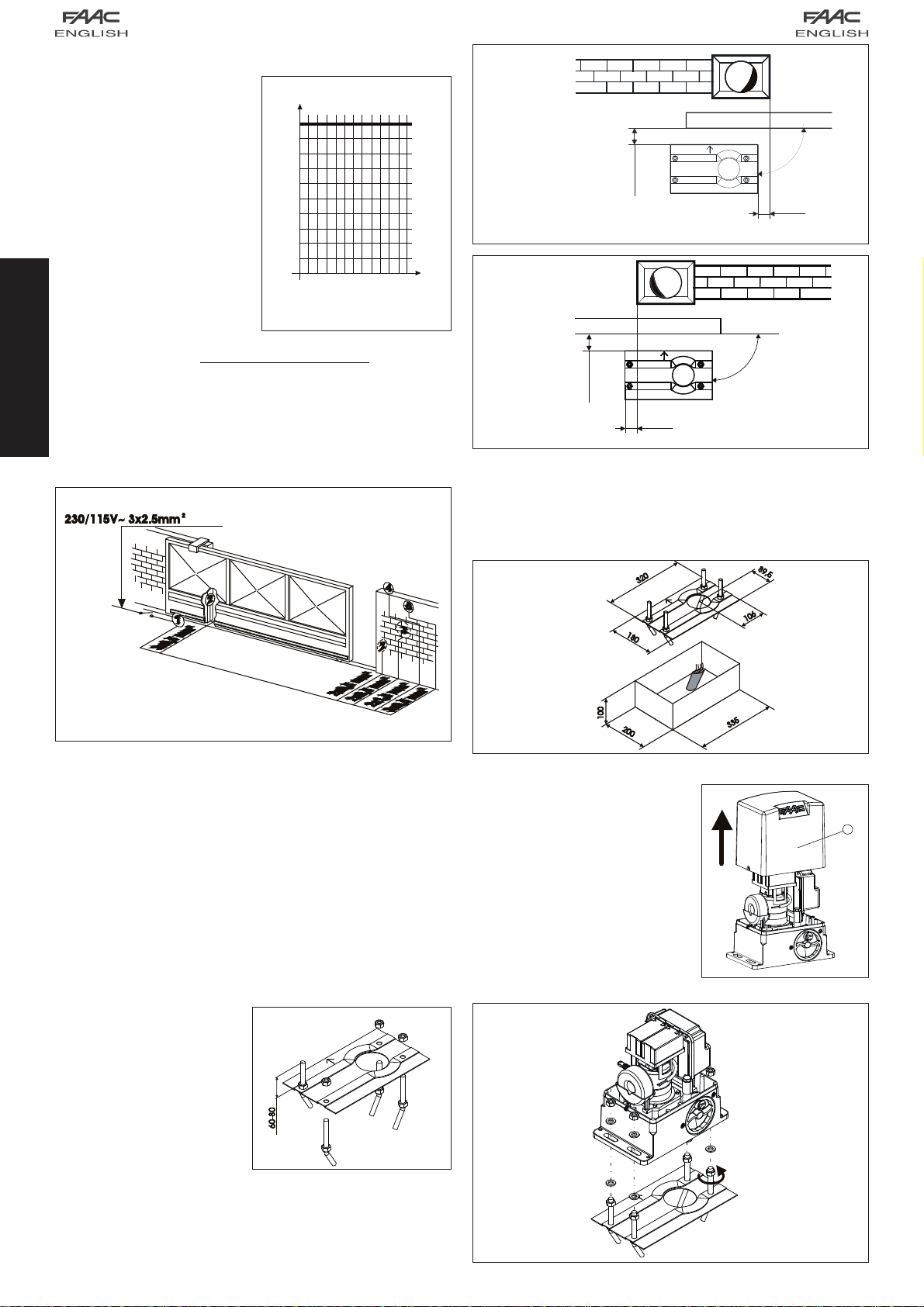
4- Secure the gearmotor to the plate, tightening the nuts.
5- Prepare the operator for manual operation as described in paragraph 8.
5.4. Assembling the rack
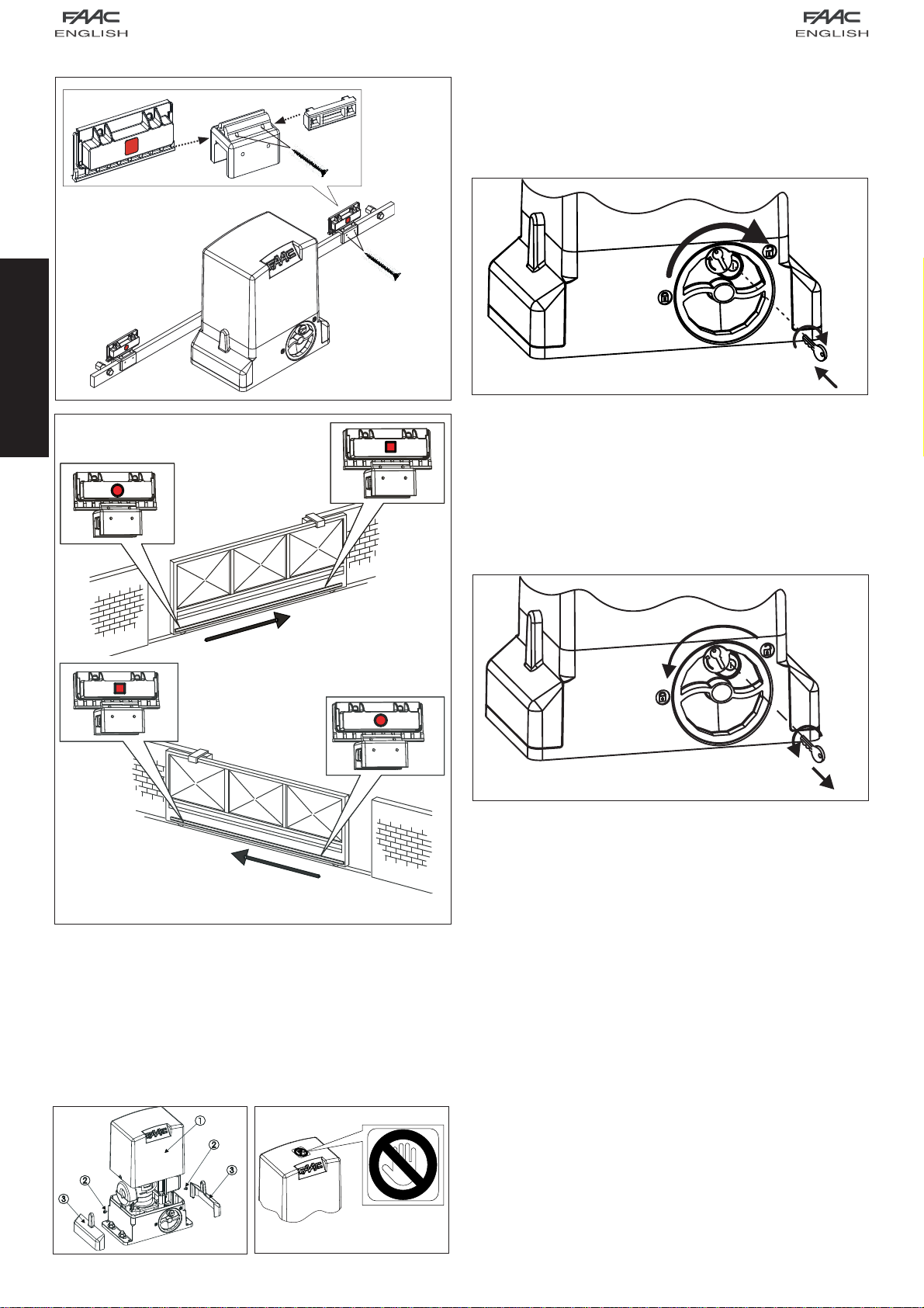
5.4.1. Steel rack to weld (Fig. 11)
1) Fit the three threaded pawls on the rack element, positioning them at the
bottom of the slot. In this way, the slot play will enable any future adjustments
to be made.
2) Manually take the leaf into its closing
position.
3) Lay the first section of rack level on the
pinion and weld the threaded pawl on
the gate as shown in Fig. 13.
4) Move the gate manually, checking if
the rack is resting on the pinion, and
weld the second and third pawl.
5) Position another rack element end
to end with the previous one, using a
section of rack (as shown in Fig. 14)
to synchronise the teeth of the two
elements.
6)Movethe gate manuallyand weld thethreethreadedpawls,thus proceeding
until the gate is fully covered.
5.4.2. Steel rack to screw (Fig. 12)
1) Manually take the leaf into its closing position.
2) Lay the first section of rack level on the pinion and place the spacer between
the rack and the gate, positioning it at the bottom of the slot.
3) Mark the drilling point on the gate. Drill a Ø 6,5 mm hole and thread with an
M8 male tap. Screw the bolt.
4) Move the gate manually, checking if
the rack is resting on the pinion, and
repeat the operations at point 3.
5) Position another rack element end
to end with the previous one, using a
section of rack (as shown in figure 14)
to synchronise the teeth of the two
elements.
6) Move the gate manually and carry
out the securing operations as for the
first element, thus proceeding until the
gate is fully covered.
Notes on rack installation
• Make sure that, during the gate travel, all
the rack elements do not exit the pinion.
•Do not, on any account, weld the rack
elements either to the spacers or to each
other.
• When the rack has been installed, to en-
sure it meshes correctly with the pinion, it is
advisable to lower the gearmotor position
by about 1.5 mm (Fig.15).
• Manually check if the gate correctly rea-
chesthemechanical limitstopsmaintaining
thepinion and rackcoupledand makesure
there is no friction during gate travel.
• Do not use grease or other lubricants
between rack and pinion.
6. START-UP
6.1. Control board connection
Before attempting any work on the board (connections, programming, mainte-
nance), always turn off power.
Follow points 10, 11, 12, 13 and14 of the GENERAL SAFETY OBLIGATIONS.
Followingthe instructionsinFig.3,route thecablesthroughtheraceways and make
the necessary electric connections to the selected accessories.
Always separate power cables from control and safety cables (push-button,
receiver, photocells, etc.). To avoid any electric noise whatever, use separate
sheaths.
6.1.1. Earthing
Connect the earth cables as shown in Fig.16 ref.A.
6.1.2. Electronic control unit
Inthegearmotors,theelectroniccontrol unitisfittedtoanadjustable support (Fig.
16 ref. 1) with transparent lid (Fig. 16 ref. 3).
Theboardprogramming push buttons (Fig.16ref.4)havebeen located on the lid.
This allow the board to be programmed without removing the lid.
For correct connection of the control unit, follow indications the specific instruc-
tions:
Values are expressed in mm
6.1.3. Connection of power cable
The740 24V gearmotor housesascrewterminalwith fuse-holder (Fig17) connected
to the primary circuit of the toroidal transformer. The mains power cable 230 / 115
V ~ must be connected to this terminal, respecting what was specified in Fig. 17. If
you have to replace the fuse, use a fuse type T1.6A/250V - 5x20 for a 230V power
supply and type T3.15A/250V - 5x20 for a 115V power supply.

5
1
2
3
1
2
3
Fig.20 Fig.21
Fig.22
Fig.23
Fig.18
Fig.19
ENGLISH
7. TESTING THE AUTOMATED SYSTEM
Afterinstalling the operator, carefully checkoperatingefficiency of all accessories
and safety devices connected to it.
Return the board support to its original position. Fit the cover, Fig. 20 ref. 1, and
tighten the two side screws provided (Fig. 20 ref 2), and snap-fit the side panels
(Fig. 20 ref.3). Apply the danger sticker on the top of the cover (Fig. 21).
Hand the “User’s Guide” to the Customer and explain correct operation and use
of the gearmotor, indicating the potentially dangerous areas of the automated
system.
8. MANUAL OPERATION
Warning: Cutpower tothesystemto preventaninvoluntary pulsefromactivating
the gate during the release manoeuvre.
To release the operator proceed as follows:
1) Insert the key provided and turn it clockwise as shown in Fig. 22 ref. 1 and 2.
2) Turn the release system clockwise, until the mechanical stop is reached, Fig.
22 ref. 3.
3) Open and close the gate manually.
9. RESTORING NORMAL OPERATION
Warning: Cutpower tothesystemto preventaninvoluntary pulsefromactivating
the gate during the manoeuvre for restoring normal operation.
To restore normal operation proceed as follows:
1) Turn the release system anti-clockwise, until its stop is reached, Fig. 23 ref. 1.
2) Turn the key anti-clockwise and remove it from the lock, Fig. 23 ref. 2 and 3.
3) Move the gate until the release system meshes (corresponds to gate
locking)
4) Power up the system.
6.2. Positioning the limit switches
10. SPECIAL APPLICATIONS
There are no special applications.
11. MAINTENANCE
Check the operational efficiency of the system at least once every 6 months,
especially as regards the efficiency of the safety and release devices (including
operator thrust force).
12. REPAIRS
For any repairs, contact the authorised Repair Centres.
13. AVAILABLE ACCESSORIES
Refer to the catalogue for available accessories.

Fig. 01 Fig. 02
1
2
3
1
2
3
740 - 24V
User’s guide
AUTOMATED SYSTEM 740-24V
Read the instructions carefully before using the product and keep them for future
consultation.
GENERAL SAFETY RULES
If installed and used correctly, the 740-24V automated system will ensure a high
degree of safety.
Some simple rules regarding behaviour will avoid any accidental trouble:
• Do not stand near the automated system and do not allow children and other
people or things to stand there, especially while it is operating.
• Keep radiocontrols or any other pulse generator well away from children to
prevent the automated system from being activated involuntarily.
• Do not allow children to play with the automated system.
• Do not willingly obstruct gate movement.
• Prevent any branches or shrubs from interfering with gate movement.
• Keep light signalling systems efficient and clearly visible.
• Do not attempt to activate the gate by hand unless you have released it.
• In the event of malfunctions, release the gate to allow access and wait for
qualified technical personnel to do the necessary work.
• After enabling manual operation, switch off the power supply to the system
before restoring normal operation.
• Do not make any alterations to the components of the automated system.
• Do not attempt any kind of repair of direct action whatsoever and contact
qualified personnel only.
• Call in qualified personnel at least every 6 months to check the efficiency of
the automated system, safety devices and earth connection.
DESCRIPTION
The 740-24V automated system is ideal for controlling vehicle access areas of
medium transit frequency.
The740-24Vautomated system for slidinggatesisan electro-mechanicaloperator
transmitting motion to the sliding gate via a rack pinion or chain appropriately
coupled to the gate.
Operation of the sliding gate is controlled by an electronic control unit housed
inside the operator or in a hermetically sealed outdoor enclosure.
When, with the gate closed, the unit receives an opening command by radio-
control or from another suitable device, it activates the motor until the opening
position is reached.
Ifautomaticoperation was set, thegatere-closes automaticallyaftertheselected
pause time has elapsed.
If the semi-automatic operation was set, a second pulse must be sent to close
the gate again.
An opening pulse during re-closing, always causes movement to be reversed.
A stop pulse (if provided) always stops movement.
The light signalling indicates that the gate is currently moving.
For details on sliding gate behaviour in different function logics, consult the instal-
lation technician.
The automated systems include obstacle-detection and/or safety devices (pho-
tocells, edges) that prevent the gate from closing when there is an obstacle in
the area they protect.
The system ensures mechanical locking when the motor is not operating and,
therefore, it is not necessary to install any lock.
Manual opening is, therefore, only possible by using the release system.
The gearmotor does not have a mechanical clutch and, therefore, it is coupled
to a unit with an electronic clutch offering the necessary anti-crushing safety if the
system is completed with the necessary safety devices.
A convenient manual release with customised key makes it possible to move the
gate in the event of a power failure or malfunction.
MANUAL OPERATION
Warning: Cutpower tothesystemto preventaninvoluntary pulsefromactivating
ENGLISH
the gate during the release manoeuvre
To release the operator proceed as follows:
1) Insert the key provided and turn it clockwise as shown in Fig. 01 ref. 1 and 2.
2) Turn the release system clockwise, until the mechanical stop is reached, Fig.
01 ref. 3.
3) Open and close the gate manually.
RESTORING NORMAL OPERATION
Warning: Cutpower tothesystemto preventaninvoluntary pulsefromactivating
the gate during the manoeuvre for restoring normal operation.
To restore normal operation proceed as follows:
1) Turn the release system anti-clockwise, until its stop is reached, Fig. 02 ref. 1.
2) Turn the key anti-clockwise and remove it from the lock, Fig. 02 ref. 2 and 3.
3) Move the gate until the release system meshes (corresponds to gate
locking).
4) Power up the system.
MAINTENANCE
To ensure trouble-free operation and a constant safety level, an overall check
of the system should be carried out every 6 months. A form for recording routine
maintenance operations is enclosed.
REPAIRS
For any repairs, contact the authorised Repair Centres.
AVAILABLE ACCESSORIES
Refer to catalogue for available accessories.
Other manuals for 740-24V
2
Table of contents
Other FAAC Engine manuals
Popular Engine manuals by other brands

Power Fist
Power Fist 8236275 user manual

Oriental motor
Oriental motor K Series operating manual

Tecnoautomazione
Tecnoautomazione GPS Series Instructions and warnings

Oriental motor
Oriental motor 4RK25GN-AM-115 instructions

Oriental motor
Oriental motor BXM230 operating manual

Oriental motor
Oriental motor World K Series operating manual

woodmizer
woodmizer LT28 G25 Safety, Operation, Maintenance & Parts Manual

woodmizer
woodmizer G18 LT30 Safety, Operation, Maintenance & Parts Manual

Tecumseh
Tecumseh V-twin Technician's handbook

MTU
MTU 8V4000Mx4 operating instructions

Siemens
Siemens CGV Installation operation & maintenance

Kohler
Kohler Command PRO CH750 Service manual