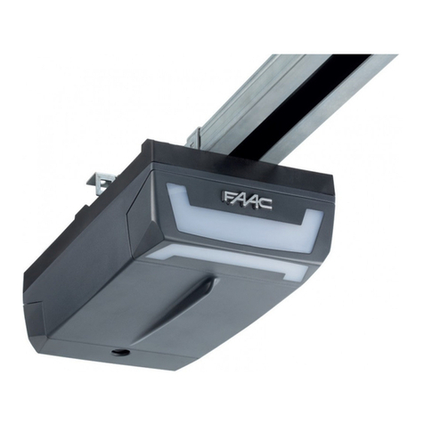
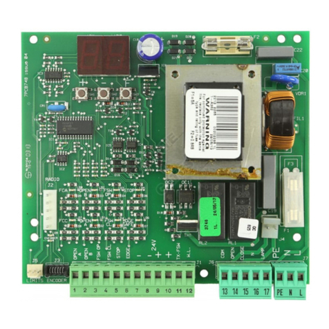
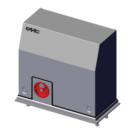
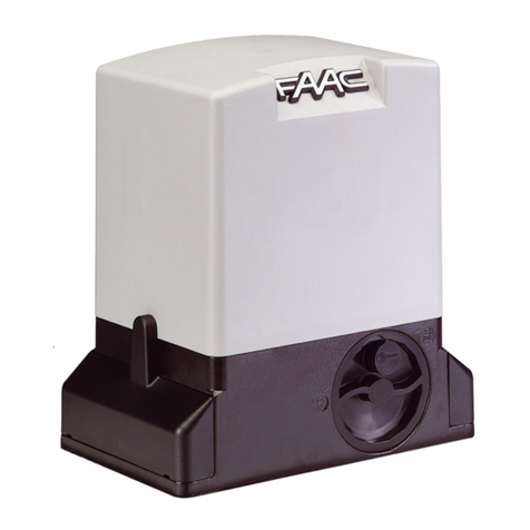
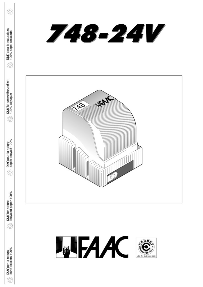
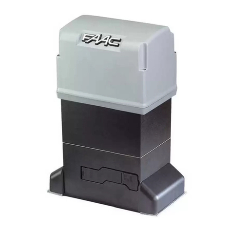
FAAC 748 User guide

C
E
R
M
E
T
A
Z
I
E
N
D
A
C
E
R
T
I
F
I
C
A
T
A
UNI EN ISO 9001-085
para la naturaleza
100% papel reciclado
ist umweltfreundlich
100% Altpapier
pour la nature
papier recyclé 100%
for nature
recycled paper 100%
carta riciclata 100%
per la natura
%"&
%"&

13
ENGLISHENGLISH
1) CAUTION! It is important for personal safety to follow all the instructions
carefully. Incorrect installation or misuse of the product may cause
people serious harm.
2) Read the instructions carefully before starting to install the product.
3) Packagingmaterial(plastic,polystyrene,etc.)mustnotbeleftwithinreach
of children as it is a potential source of danger.
4) Keep the instructions in a safe place for future reference.
5) This product was designed and manufactured strictly for the use indicated
inthis documentation. Any other not expressly indicated use may damage
the product and/or be a source of danger.
6) FAAC accepts no responsibility due to improper use of the automation or
use other than that intended.
7) Do not install the appliance in an area subject to explosion hazard: inflam-
mable gasses or fumes are a serious safety hazard.
8) Thesystemmustbeconstructedincompliance with thefollowingStandards:
EN12604, EN12605, EN12453,EN12445 .
For non-EU countries, to obtain an adequate level of safety, the Standards
mentioned above must be observed, in addition to national legal
regulations.
9) FAAC will not accept responsibility if the principles of good workmanship
are disregarded in constructing the closing elements to be motorised, and
if any deformation occurs during use of the said elements.
10) Before carrying out any work on the system, switch off the electricity
supply.
11) The mains electricity supply of the automation must be fitted with a single-
pole switch with contact opening distance of 3mm or greater. Use of a 6A
thermal breaker with single-pole circuit break is recommended.
12) Make sure there is a differential switch with 0.03A threshold upstream of the
system.
13) Check that the earthing system is correctly made and connect the closure
metal parts to it. Also connect the Yellow/Green wire of the automation to
theearthing system.
14) The automation includes an intrinsic anti-crushing device consisting of a
torquecontrolwhich,however, must be installed together with other safety
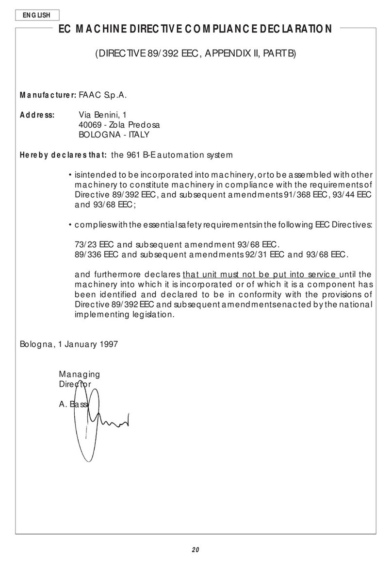
CE DECLARATION OF MACHINE CONFORMITY
(DIRECTIVE 89/392/EEC, ANNEX II, PART B)
Manufacturer : FAAC S.p.A.
Address: Via Benini, 1 - 40069 Zola Predosa BOLOGNA - ITALY
Declares that: Operator mod. 748 with electronic control unit 748D,
• is manufactured to be incorporated in a machine or for assembly with other machines to constitute a machine
under the provisions of Directive 89/392/EEC, and subsequent amendments 91/368/EEC, 93/44/EEC, 93/68/EEC;
• conforms to the essential safety requirements of the following further EEC Directives:
73/23/EEC and subsequent amendment 93/68/EEC.
89/336/EEC and subsequent amendment 92/31/EEC and 93/68/EEC
and, furthermore, declares that putting the machine into service is forbidden until the machine in which it will
be incorporated or of which it will become a part has been identified and it has been declared as conforming
to the conditions of Directive 89/392/EEC and subsequent amendments enacted by the national implementing
legislation.
Bologna, 01 January 2002
The Managing Director
A. Bassi
devices.
15) The safety devices [e.g.: photocells, sensitive edges, etc…] protect any
dangerous areas against Movement mechanical risks, such as, crushing,
dragging, or shearing.
16) Use of at least one indicator-light is essential for each system (e.g.: FAAC
LAMP MINILAMP, etc.) as well as a sign adequately fixed to the frame
structure, in addition to the devices mentioned at point “16”.
17) FAAC accepts no responsibility regarding safety and correct operation
of the automation, should components made by manufacturers other
than FAAC be used in the system.
18) Use only FAAC original spare parts for maintenance.
19) Do not make any alterations to the components of the automation.
20) The installer must supply full information regarding manual operation of
the system in the event of an emergency and provide the user of the
system with the “User’s Guide” included with the product.
21) Do not allow children or other persons to stand near the product while in
operation.
22) Keep remote controls or any other pulse generator well away from chil-
dren, to prevent the automation from being activated accidentally.
23) Theuser must refrain from attempting to repair or adjust the system person-
ally and should contact qualified personnel only.
24) Anything not expressly provided for in these instructions is not permitted.
WARNING FOR THE INSTALLER
GENERAL SAFETY OBLIGATIONS

14
ENGLISH ENGLISH
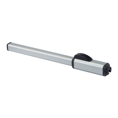
748 AUTOMATION SYSTEM
The FAAC 748 automation system for sliding residential gates is an
electromechanical operator that transmits the leaf movement by
means of a pinion coupled to a rack fixed to the gate.
The irreversible system locks mechanically when the motor is not
running, so it is not necessary to install a lock.
1. DESCRIPTION AND TECHNICAL SPECIFICATIONS
Table 1: Technical specifications of 748 115Vac and 230Vac
Operator
Model 748-115V 748-230V
Power supply Vac(+6-10%) 50Hz 115 230
Absorbed power (W) 600 350
Current drawn (A) 5 1.6
Electric motor 4 poles - 1400rpm 4 poles - 1400 rpm
Surge capacitor 30µF/450V 10µF/450V
Reduction ratio 1:25
Pinion Z16
Rack module 4 - pitch 12.566
Max. torque (Nm) 15
Max. thrust (daN) 45 (Z16)
Thermal cutout on winding 140°C
Duty cycle (
see paragraph 1.1
)
Temperature range (°C) -20 쐦+55 °C
Weight of operator (Kg) 10
Housing protection IP 44
Max. gate weight (Kg) 300
Gate speed (m/min) 12 (Z16)
1.1. MAXIMUM DUTY CYCLE CURVE
The curve makes it possible to determine the maximum operating time (T) as a
function of the duty cycle (F), e.g., the 748 operator can work continuously at a duty
cycle of 25%.
To ensure smooth running, operation should be kept within the duty
area below the curve.
Important
: the curve was plotted on the basis of operation at 24 °C.
Allow for up to 20% reduction of duty cycle in case of exposure to
direct sunlight.
Calculating the duty cycle
The duty cycle is the proportion of
the actual operating time (opening
+ closing) with respect to the total
time of the cycle (opening + closing
+ pause time).
The formula for calculating it is the
following:
%F= To + Tc x 100
To + Tc + Tp + Ti
where:
To = opening time;
Tc = closing time;
Tp = pause time;
Ti = duration of interval between a
complete cycle and the next one.
2. STANDARD INSTALLATION LAYOUT
10
20
30
40
50
60
70
80
90
100
01234567891010 1 1 12
Percentuale
di lav. %
Tiempo (h)
% Duty cycle % Fréquence
d'utilisation
% Benutzungs-
frequenz
% Frecuencia
de utilización
Zeit (Std.)Temps (h)Time (h)Tempo (h)
3. INSTALLATION OF AUTOMATION SYSTEM
3.1. PRELIMINARY CHECKS
To ensure trouble-free operation, make sure that the gate (whether
existing or yet to be installed) has the following specifications:
•Max. gate weight 300 kg.
•Strong and rigid leaf frame.
•Flat leaf face, with no protruding parts and no vertical members.
•Smooth and even movement of the gate over its entire travel.
•No sideways oscillation of the leaf.
•Upper and lower sliding system in perfect conditions. The use of floor tracking with
a rounded channel is preferable to reduce friction in the sliding movement.
•Only two slide wheels.
•Mechanical safety stops to avoid risk of derailment. These stops must
be firmly fixed to the ground or to the floor track, about 2 cm beyond
the travel limit.
•No mechanical locks.
If any welding or brazing is required on the gate, it should be done
before installing the automation system.
The condition of the structure directly affects the reliability and safety of the
automationsystem.
햲Cover
햳Supports for cover guides (2)
햴Support for electr. control unit
햵Electronic control unit
햶Opening for cables
햷Releasing device with key
햸Bores for fastening cover (4)
햹Slots for fastening operator
햺Mechanical travel stop
햻Pinion Z16
햽Electric motor
햾Earth connection of operator
Fig. 1
!
"
'
&$
%
#
TX
햲748 Operator
햳Photocells
햴Key-operated pushbutton
햵Flashing lamp
햶Radio receiver
•Use suitable rigid/flexible pipes for laying power cables.
•Always keep low voltage accessory cables separate from power cables.
To avoid interference, use separate sheaths.
Fig. 2

15
ENGLISHENGLISH
3.2. INSTALLING THE OPERATOR
1)Dig out a hole for the base plate as
shown in fig. 3.
In order to ensure the correct
engaging of the pinion and rack, the
base plate must be placed in the
position shown in fig. 4a (right closing)
or 4b (left closing).
N.B.
it is advisable to place the base plate on a concrete foundation at about 50 mm
from the ground (fig. 5).
2) Lay the flexible pipes for connection cables between operator,accessories,and
power supply.The flexible pipes must protrude by approximately 3 cm from the
opening on the plate (fig 3).
3) Cement in the plate, ensuring that it is perfectly level.
4) Wait for the concrete to set in the hole.
5) Lay the cables for connection with accessories and power supply.To facilitate
the electrical wiring on the electronic unit, about 30 cm of cable should come
out of the opening on the base plate.
6) Fasten the operator to the base plate by means of the screws and washers
supplied, as shown in fig. 6.
The positioning of the operator is shown in fig. 5.
Pass the electrical cables through the relevant
opening (fig.1 - ref.5) on the base of the operator.
7)Pass the electrical connection cables through the
relevant opening on the base of the electronic
control unit support (fig. 1 - ref. 3), using the cable
clamp supplied.
8) Connect up the cables to the electronic control
unit.
Important
: connect up the earth cable of the
system to the position shown in fig. 1 - ref. 12.
Fig. 3
3.3. ASSEMBLING THE RACK
1) Fit the rack by means of the screws TE 8 x 25 and the spacers provided, as shown
in figure 7.
To avoid welding to the gate,galvanized passing spacers with screwsTE 8 x 50 are
provided.
N.B.
it is advisable to tighten the rack fixing screws at the top of the slot. This allows
the rack to be raised if, with time, the gate tends to sink.
2) Release the operator (see paragraph 3.5).
3) Slide the gate leaf open, by hand.
4) Place the first section of the rack on the pinion,
aligning the latter with the first spacer (fig. 8).
5) Fix the rack section to the leaf by means of a
clamp (fig. 8).
6) Slide the gate leaf by hand towards its closed
position, until it is in line with the third spacer on
the rack, and spot weld the spacer in position.
7) Completely weld the three spacers to the gate.
To fasten the other rack sections needed to reach the position of complete
closing, proceed as follows:
8) Line up another rack section to the last one fixed to the gate. Use a section of rack
of about 150 mm and ensure that the teeth are correctly spaced (fig. 9).
9) Slide the gate by hand towards its closed position until the third spacer of the
section to be fastened is aligned with the pinion (fig. 9).
N.B.
ensure that all the rack sections are correctly centered on the pinion teeth.
If not,adjust the position of the operator.
10)Weld the three spacers of the section (fig. 9).
Caution
:
a) do not weld the rack sections to the spacers or to each other;
b) do not use grease or other lubricants on the pinion and rack.
11)To obtain a correct slack between the pinion and rack,lower the operator by 1.5
mm, by means of the support nuts of the base plate (fig. 10).
When this adjustment has been completed, tighten the screws that fasten the
operator.
Caution:
If the gate is new,check the slack (fig.11) after a few months.
12)Manually check whether the gate can open completely and the movement of
the leaf is smooth and even, over its entire travel.
Fig. 6
Fig. 7
70 72÷
0 50
÷200
90°
70 72÷
0 50÷
120
90°
Fig. 4b
Fig. 4a
'
50
! &&
14,5÷23
70
# !
Fig. 5
Fig. 8 Fig. 9
1.5
Fig. 10 Fig. 11

16
ENGLISH ENGLISH
3.4. POSITIONING TRAVEL LIMIT PLATES
The 748 operator is equipped with an electro-mechanical travel
limit switch with roller,which,when a profiled plate secured at the
top of the rack activates its lever,commands the gate movement
to slow down and stop. Procedure for correct positioning of the
two travel limit plates supplied:
1) Power up the system.
2) Manually take the gate to opening position, leaving a space
of 2 cm from the mechanical travel limit stop position.
3) Slide the plate along the rack in opening direction and check
if the switch is activated before the end of the profiled part
(the FCA LED on the 748D equipment goes OFF).
4) Allow the plate to advance further until the switch wheel is
about 2-3 cm from the end of the plate’s straight area and
secure it provisionally.
5) Manually take the gate to closing position, leaving a space of
2 cm from the mechanical stop.
6) Slide the plate along the rack in closing direction and check if
the switch is activated before the end of the profiled part (the
FCC LED on the 748D equipment goes OFF).
7) Allow the plate to advance further until the switch wheel is
about 2-3 cm from the end of the plate’s straight area and
secure it provisionally.
8) When the slow-down and/or braking time (see instructions for
the 748D equipment) has been programmed, it may be
necessary to slightly correct the position of the plates, if the
stop points are not as required. If this operation is performed,
you must make sure that the gate never stops less than 2 cm
from the mechanical travel limit stops and that the electro-
mechanical travel limit wheel is at least 2 cm from the end of
the plate’s straight area; if necessary,adjust the slowing down
time and/or straighten the final profiled part of the plate (see
fig.12).
9) Re-lock the system. Important: before sending an opening or
closing pulse, make sure that the gate cannot be moved
manually.
10) Command a few complete cycles of the automated system,
checking that the gate never reaches the mechanical travel
limit stops.
3.5. MANUAL OPERATION
Should the need arise to operate the gate manually because of
a power failure or malfunction, release it by means of the releasing
device.
Proceed as follows:
•open the lid of the lock and insert the relative key in the lock
(fig. 13);
•turn the key clockwise and open the cover of the releasing
device as shown in figure 13.
To re-lock the system,return the cover of the releasing device to
its initial position.
Important
: before giving a signal, ensure that the gate cannot
be moved manually.
N.B.:
re-lock always the operator with gate in closed position.
4. START-UP
1) When you have carried out all the electrical connections,
locked the operator, and checked that it cannot be moved
by hand, power up the system.
2)Program the 748D equipment. Check the status of the
equipment’s inputs and verify if all safety devices are correctly
connected (the relevant LEDs must be lighted).
3) Run a few complete cycles to check if the automated system
and the accessories connected to it are operating correctly,
giving special attention to safety devices and to the
adjustment of the operator’s thrust force.
4) Hand over the User’s Guide to the customer,and describe how
the system works, as well as the operator release and locking
operations indicated in the said guide.
Fig. 12
Fig. 13

17
ENGLISHENGLISH
USER’S GUIDE
748 AUTOMATION
Read the instructions carefully before using the product and
keep them for future reference.
GENERAL SAFETY INSTRUCTIONS
The 748 automation, when installed and used correctly,
affords a high level of safety.
However, some simple rules should be followed to avoid
accidents:
- Do not stand in the vicinity of the automation or allow
anyone else, especially children, to do so, and do not
place objects in the vicinity of the automation. This is
particularly important during operation.
- Keep remote controls or any other control devices out of
the reach of children to prevent them from accidentally
operating the automation.
- Do not allow children to play with the automation.
- Do not deliberately obstruct the movement of the gate.
- Make sure that branches or bushes do not interfere with
the movement of the gate.
- Ensure that the signalling lights are efficient and clearly
visible.
- Do not attempt to move the gate manually without first
releasing it.
- In the event of a malfunction, release the gate to allow
access and call a qualified technician for service.
- After setting manual operation, disconnect the electricity
supply from the system before returning to normal
operation.
- Do not make any modifications to components of the
automation system.
- Do not attempt to perform any repair work or tamper with
the automation. Call FAAC qualified personnel for repairs.
- At least once every six months have the automation, the
safety devices and the earth connection checked by a
qualified technician.
DESCRIPTION
The FAAC 748 automation is ideal for residential applications.
The FAAC model 748 automation for sliding gates are
electromechanical operators which transmit movement to
the leaf by means of a pinion with rack coupled in
appropriate manner to the sliding gate.
The operation of the sliding gate is controlled by an
electronic control unit housed inside the operator.
When the gate is closed, on receipt of an opening impulse
from a remote control or other suitable control device, the
control unit will start the motor to move the gate to the open
position.
If automatic operation has been selected, sending an
impulse causes the gate to reclose on its own after the
selected pause time.
If semiautomatic operation has been selected, a second
impulse must be sent to reclose the gate.
A stop command (if available) stops movement at any time.
For detailed information on operation of the sliding gate in
the various operating modes, contact the installation
technician.
The automations have safety devices (photocells) which
prevent the gate from reclosing when an obstacle lies within
the area they are protecting.
The system ensures mechanical locking when the motor is
not in operation, so it is not necessary to install a lock.
For this reason the release system must be operated before
the gate can be opened manually.
A convenient manual release device allows the gate to be
operated in the event of a power failure or malfunction.
The light flashes while the gate is moving.
MANUAL OPERATION
Should the need arise to operate the gate manually
because of a power failure or malfunction, release it by
means of the releasing device.
Proceed as follows:
•open the lid of the lock and insert the relative key in the
lock (fig. 1);
•turn the key clockwise and open the cover of the releasing
device as shown in figure 1.
To re-lock the system,return the cover of the releasing device
to its initial position.
Important
: before giving a signal, ensure that the gate
cannot be moved manually.
N.B.:
re-lock always the operator with gate in closed position.
Fig. 1

17
ENGLISH
24 Vdc
3 W
C
M
24V
1 2 3 4 5 6 7 8 9 10 11 12 13 14 15 16 17 PE N L
EDGE
W.L.
TX-FSW
+
LIMITS ENCODER MOTOR
ACCESSORIES LAMP MAIN
N
L
STOP
+
--
OPEN
B
A
OPEN
FSW OP
FSW CL
COM
OPEN
CLOSE
LAMP
PE
N
J1
J7
J5 J3
J6
24V
F1
F2
1 2 3 4 5 6 7 8 9 10 11 12 13 14 15 16 17 PE N L
EDGE
W.L.
TX-FSW
+
LIMITS ENCODER MOTOR
ACCESSORIES LAMP MAIN
N
L
F
+
RADIO
FCA
FCC
OPEN
B
FSW
CL
STOP
SAFE
OPEN
A
FSW
STOP
+
--
OPEN
B
A
OPEN
FSW OP
FSW CL
COM
OPEN
CLOSE
LAMP
PE
N
ENCODER
EDGE
OP
-
J1
J7
J5 J3
J6
J2
Fig. 1
NB.: The capacitor is supplied with the operator.
Fig. 2
TOTALLY OPEN
PARTIALLY OPEN
STOP
CONTROL BOARD 748D
DL SIGNALLINGANDPROGRAMMINGDISPLAY
Led INPUTSSTATUSCONTROL LED
J1 LOWVOLTAGETERMINALBOARD
J2 CONNECTORFORDECODER/MINIDEC/RPRECEIVER
J3 ENCODERCONNECTOR
J5 LIMIT-SWITCHCONNECTOR
J6 MOTORSANDFLASHINGLAMPCONNECTIONTERMINALBOARD
J7
POWERSUPPLYTERMINALBOARD115Vac(748D-115V)-230Vac(748D-230V
)
F1
MOTORSAND TRANSF. PRIMARY FUSE (748D115V=F10A - 748D230V=F5A)
F2 LOWVOLTAGEAND ACCESSORIESFUSE (T800mA)
F"F"PROGRAMMINGPUSH-BUTTON
–"–"PROGRAMMINGPUSH-BUTTON
+"+"PROGRAMMINGPUSH-BUTTON
F
F1
F2
J1
J2
J3
J5
J6
DL
–+
Model 748D-115V 748D-230V
Power supply
V~
( +6% -10%) 50 Hz
115 230
Absorbed power (W) 10 10
Motor max. load (W) 1200 1000
Accessories max. load (A) 0.5 0,5
Operating ambient temperature -20 °C +55 °C
Protection fuses 2 (see fig. 1)
Function logics Automatic / "Stepped" automatic /
Semi-automatic / Safety devices / Semi-automatic B / Dead-man C /
"Stepped" semi-automatic
Work time Programmable (from 0 to 4 min.)
Pause time Programmable (from 0 to 4 min.)
Thrust force Adjustable over 50 levels
Terminal board inputs Open / Partial opening / Safety devices at opng. /
Safety devices at clsng. / Stop / Edge / Power supply + Earth
On-connector inputs Opening and closing limit-switches / Encoder
Terminal board outputsFlashing lamp - Motor - 24 Vdc accessories power
supply - 24 Vdc indicator-light / Timed output. - Fail safe
Rapid connector 5-pin card connection for Minidec, Decoder or RP receivers
Programming 3 keys (+, -, F) and display, "basic" or "advanced" mode
Basic mode programmable functions Function logic - Pause time - Thrust
Force - Gate direction
Advanced mode programmable functions Torque at initial thrust - Braking -
Fail safe - Pre-flashing - Indicator-light/Timed output -
Opening and closing safety devices logic -
Encoder - Decelerations - Partial opening time -
Work time - Assistance request - Cycle counter
For connection of the
photocells and safety
devices, see paragraph
4.1.
BLUE
LIMIT-SWITCH
ENCODER
(optional)
1. WARNINGS
Important: Before attempting any work on the control board
(connections, maintenance), always turn off power.
- Install, upstream of the system, a differential thermal breaker with
adequate tripping threshold.
- Connect the earth cable to the appropriate terminal on the J7
connector of the equipment (see fig.2).
- Always separate power cables from control and safety cables
(push-button, receiver, photocells, etc.). To avoid any electric
noise, use separate sheaths or a shielded cable (with earthed
shield).
2. TECHNICAL SPECIFICATIONS
3. LAYOUT AND COMPONENTS
Led
J7
4. ELECTRIC CONNECTIONS
115Vac
(748D 115V)
max. 60W
-
230 Vac
(748D 230V)
max. 60W
115Vac 50-60Hz
(748D 115V)
-
230Vac 50-60Hz
(748D 230V)

18
ENGLISH
Opening/closing
safety devices
Closing safety device
Opening safety
devices
Fig. 3
Connection of no safety device
Fig. 5
4.1.
Connectionofphotocellsandsafety devices
Before connecting the photocells (or other devices) we advise
you to select the type of operation according to the movement
area they have to protect (see fig.3):
"Edge" safety devices
Opening safety devices:
they operate only during the gate
opening movement and, therefore, they are suitable for
protecting the area between the opening leaf and
fixed obstacles (walls, etc) against the risk of impact and
crushing.
Closing safety devices:
they operate only during the gate
closing movement and, therefore, they are suitable for
protecting the closing area against the risk of impact.
Opening/closing safety devices:
they operate during the gate
opening and closing movements and, therefore, they
are suitable for protecting
the opening and closing
areas against the risk of impact.
"Edge" safety devices:
they operate during the gate opening
and closing movements and, therefore, they are suitable
for protecting the areas between the moving leaf and
fixed obstacles (pillars, walls, etc) against the risk of
shearing and dragging.
Encoder (optional):
operates during the gate opening and
closing movements and, therefore, it is suitable for
protecting the opening and closing area against the risk
of impact, crushing, shearing and dragging.
N.B. If two or more safety devices have the same function
(opening, closing, opening and closing, edge), the contacts
must be connected to each other in series (fig. 4).
N.C. contacts must be used.
The most common photocell and safety device lay-outs are
shown below (from fig. 6 to fig. 13).
Fig. 4
Connection of two N.C. contacts in series
(e.g. Photocells, Stop, Edge, etc.)
N.B: If safety devices are not used, jumper connect the terminals
as shown in fig. 5.
24V
1 2 3 4 5 6 7 8 9 10 11 12
EDGE
W.L.
TX-FSW
+
STOP
+
--
OPEN
B
A
OPEN
FSW OP
FSW CL
Connection of an "edge" safety device
Fig. 7
24V
1 2 3 4 5 6 7 8 9 10 11 12
EDGE
W.L.
TX-FSW
+
STOP
+
--
OPEN
B
A
OPEN
FSW OP
FSW CL
1
2
5
4
3
1
2
RX TX
-
+
-
+
24V
1 2 3 4 5 6 7 8 9 10 11 12
EDGE
W.L.
TX-FSW
+
STOP
+
--
OPEN
B
A
OPEN
FSW OP
FSW CL
Fig. 8
Connection of a pair of photocells for opening
Connection of a pair of closing photocells
Fig. 9
1
2
5
4
3
1
2
RX TX
-
+
-
+
24V
1 2 3 4 5 6 7 8 9 10 11 12
EDGE
W.L.
TX-FSW
+
STOP
+
--
OPEN
B
A
OPEN
FSW OP
FSW CL
Connection of a closing safety device and an opening
safety device
Fig. 6
24V
1 2 3 4 5 6 7 8 9 10 11 12
EDGE
W.L.
TX-FSW
+
STOP
+
--
OPEN
B
A
OPEN
FSW OP
FSW CL
Connection of a pair of opening photocells, a pair of
closing photocell and an edge safety device
1
2
5
4
3
1
2
RX CL TX CL
1
2
5
4
3
1
2
RX OP
TX OP
-
-
-
-
+
+
+
+
24
V
1 2 3 4 5 6 7 8 9 10 11 12
EDGE
W.L.
TX-FSW
+
STOP
+
--
OPEN
B
A
OPEN
FSW OP
FSW CL
Fig. 10

19
ENGLISH
Fig. 14
Connection of two N.O. contacts in parallel
(e.g. Open A, Open B)
Fig. 11
Connection of two pairs of closing photocells and two
edge safety devices
1
2
5
4
3
1
2
RX CL1 TX CL1
1
2
5
4
3
1
2
RX CL2
TX CL2
-
+
-
+
24
V
1 2 3 4 5 6 7 8 9 10 11 12
EDGE
W.L.
TX-FSW
+
STOP
+
--
OPEN
B
A
OPEN
FSW OP
FSW CL
Connection of a pair of closing photocells and a pair of
opening/closing photocells
Connection of a pair of closing photocells, a pair of opening
photocells and a pair of opening/closing photocells
Fig. 12
1
2
5
4
3
1
2
RX CL TX CL
1
2
5
4
3
1
2
RX OP/CL
TX OP/CL
-
+
-
+
1
2
5
4
3
1
2
RX OP TX OP
-
+
-
+
24V
1 2 3 4 5 6 7 8 9 10 11 12
EDGE
W.L.
TX-FSW
+
STOP
+
--
OPEN
B
A
OPEN
FSW OP
FSW CL
1
2
5
4
3
1
2
RX CL TX CL
1
2
5
4
3
1
2
RX OP/CL
TX OP/CL
-
+
-
+
24V
1 2 3 4 5 6 7 8 9 10 11 12
EDGE
W.L.
TX-FSW
+
STOP
+
--
OPEN
B
A
OPEN
FSW OP
FSW CL
4.2. J7 Terminal board - Power supply (fig. 2)
POWER SUPPLY (terminals PE-N-L):
PE: Earth connection
N:Power supply ( Neutral )
L:Power supply ( Line )
NB.: For correct operation, the board must be connected to the
earth conductor in the system. Install an adequate differential
thermal breaker upstream of the system.
4.3. J6 Terminal board - Motors and flashing lamp (fig. 2)
MOTOR - (terminals 13-14-15): Motor connection.
In gearmotors with a built-in control unit, this connection is pre-
wired standard. For leaf opening direction, see basic
programming in Chpt 5.1.
LAMP - (terminals 16 -17): Flashing lamp output.
4.4. J1 Terminal board - Accessories (fig. 2)
OPEN A - "Total Opening" command (terminal 1): any pulse
generator (push-button, detector, etc.) which, by closing
a contact, commands total opening and/or closing of the
gate leaf.
To install several total opening pulse generators, connect
the N.O. contacts in parallel (see fig. 14).
OPEN B - "Partial opening " or "Closing" command (terminal
2): any pulse generator (push-button, detector, etc.)
which, by closing a contact, commands partial opening
and/or closing of the gate leaf. In the Band Clogics, it
always commands gate closure.
To install several partial opening pulse generators, connect
the N.O. contacts in parallel (see fig. 14).
Fig. 13

20
ENGLISH
FSW OP - Opening safety devices contact (terminal 3): The
purpose of the opening safety devices is to protect the leaf
movement area during opening. During opening, in the A-
AP-S-E-EP logics the safety devices reverse the movement
of the gate leaves, or stop and restart the movement when
they are released (see advanced programming in Chpt
5.2). During the opening cycle in logics Band C, they
interrupt movement. They never operate during the closing
cycle.
If the Opening safety devices are engaged when the gate
is closed, they prevent the leaf opening movement.
To install several safety devices, connect the N.C. contacts
in series (fig.4).
NB.: If no opening safety devices are connected, jumper
connect inputs OP and -TX FSW (fig. 5).
FSW CL - Closing safety devices contact (
terminal
4): The
purpose of the closing safety devices is to protect the leaf
movement area during closing. During closing, in the A-
AP-S-E-EP logics, the safety devices reverse the movement
of the gate leaves, or stop and reverse the movement
when they
are released
(
see advanced programming in
Chpt 5.2
). During the closing cycle in logics Band C, they
interrupt movement. They never operate during the
opening cycle. If the Closing safety devices are engaged
when the gate is open, they prevent the leaf closing
movement.
To install several safety devices, connect the N.C. contacts
in series (fig.4).
NB.: If no closing safety devices are connected, jumper
connect terminals CL and -TX FSW (fig. 5).
STOP - STOP contact (
terminal
5): any device (e.g. a push-
button) which, by opening a contact, is able to stop
gate movement.
To install several STOP devices, connect the N.C. contacts
in series.
NB.: If STOP devices are not connected, jumper connect
the STOP and - terminals.
EDGE - EDGE safety device contact (terminal 6): The purpose of
the "edge" safety device is to protect the leaf movement
area during opening/closing against fixed obstacles (pillars,
walls, etc.). In all logics, during opening and closing, the
safety devices reverse gate leaf movement for 2 seconds.
If the safety devices operate again during the 2-seconds
reversing time, they STOP movement without any reversing.
If the Edge safety devices are engaged while the gate is
closed or open, they prevent the leaves movement.
To install several safety devices, connect the N.C. contacts
in series (fig.4).
NB.: If edge safety devices are not connected, jumper
connect the EDGE and - inputs. (fig. 5).
– Negative for power supply to accessories (terminals 7 and
8)
+ 24 Vdc - Positive for power supply to accessories (terminals
9 and 10)
Important: Accessories max. load is 500 mA. To calculate
absorption values, refer to the instructions for individual
accessories.
TX -FSW - Negative for power supply to photocell transmitters
(terminal 11)
If you use this terminal for connecting the negative for
supplying power to the photocell transmitters, you may,
if necessary, also use the FAIL SAFE function (see advanced
programming in Chpt 5.2).
If this function is enabled, the equipment checks
operation of the photocells before every opening or
closing cycle.
W.L. - Power supply to indicator-light / timed output (terminal
12)
Connect a 24 Vdc - 3 W max indicator-light or timed
output, if necessary, between this terminal and the +24V
supply (see advanced programming in Chpt 5.2).To
avoid geopardising correct operation of the system, do
not exceed the indicated power.
Fig. 16
Fig. 15
Fig. 17
MINIDEC
PLUS
PLUS
DECODER
RP
4.5.
ConnectorJ2-RapidconnectiontoMinidec,DecoderandRP
This is used for rapid connection of Minidec, Decoder and RP
receivers(see fig. 15, 16 and 17). Connect the accessory, withthe
componentssidefacing the insideofthe board. Insertand remove
after cutting power.
4.6. Connector J6 - Limit-switches rapid connection (fig.2)
This input is intended for rapid connection of the opening and
closing limit-switches designed to stop the leaf, or for start of
decelerations or for braking (see advanced programming in
Chpt.5.2.).In gearmotors withabuilt-in control unit,thisconnection
is pre-wired as standard (fig. 2). For leaf opening direction, see
advanced programming in Chpt 5.2.
4.7. Connector J3 - Encoder rapid connection (fig.2)
This input is designed for rapid connection of the Encoder
(optional). To fit the encoder on the motor, refer to the relevant
instructions.
The presence of the encoder is signalled - when the gearmotor
is running - by the flashing of the "Encoder" LED on the board.
When the encoder is used, the control unit knows the exact
position of the gate while it is moving.
The encoder controls the adjustments of some of the control
unit'sfunctions in adifferent way (partial opening or deceleration
- see advanced programming in Chpt 5.2) and as an anti-
crushing device.
If the gate strikes an obstacle during opening or closing, the
encoder immediately reverses the gate leaf for 2 seconds. If the
encoder operates again during the 2-seconds reversing time,
it STOPS movement without commanding any reversing.
748D 748D
748D

21
ENGLISH
BASIC PROGRAMMING F
Display Function Default
FUNCTION LOGICS (see tab. 3/a - g):
= Automatic
= "Stepped" automatic
= "Safety" Automatic
= Semi-automatic
= "Stepped" Semi-automatic
= Dead-man
= "B" Semi-automatic
PAUSE TIME:
Thishas effect only if the automatic logic was
selected. Adjustable from to sec. in
one-second steps.
Subsequently, display changes to minutes
and tens of seconds (separated by a point)
and time is adjusted in 10-second steps, up
to the maximum value of minutes.
E.g. if the display shows , pause time is
2 min. and 50 sec.
FORCE:
Adjusts Motor thrust.
= minimum force
= maximum force
OPENING DIRECTION:
Indicates the gate opening movement and
makes it possible not to change the motor
andlimit-switch connections on the terminal
board.
= Right-hand opening movement
= Left-hand opening movement
5. PROGRAMMING
To program operation of the automated system, you have to
access the "
PROGRAMMING
" mode.
Programming is split into two parts:
BASIC
and
ADVANCED
.
5.1. BASIC PROGRAMMING
To access BASIC PROGRAMMING, press key F:
•if you press it (and hold it down), the display shows the name of
the first function.
•if you release the key, the display shows the value of the function
that can be modified with keys +and -.
•if you press Fagain (and hold it down), the display shows the
name of the next function, etc.
•when you reach the last function, press Fto exit the program,
and the display resumes showing the gate status.
The following table shows the sequence of functions accessible in
BASIC PROGRAMMING:
ADVANCED PROGRAMMING F+
+
Display Function Default
MAXIMUM TORQUE AT INITIAL THRUST:
The motor operate at maximum torque
(ignoring the torque setting) at start of
movement. Useful for heavy leaves.
= Active
= Disabled
FINAL BRAKING:
When the gate engages the opening or
closing limit-switch, a braking stroke can
be selected to ensure the leaf is stopped
immediately. If decelerations are selected,
braking starts when they finish.
At value, braking is disabled.
Time can be adjusted from to
sec. in 0.1-second steps.
E.g. if the display indicates , braking
time is 1 second.
= Braking disabled
from to = Timed braking
FAIL SAFE:
If this function is activated, it enables a
function test of the photocells before any
gate movement. If the test fails (photocells
not serviceable signalled by value on
the display), the gate does not start moving.
= Active
= Disabled
PRE-FLASHING (5 s):
Activates the flashing lamp for 5 sec. before
start of movement.
= Active
= Disabled
5.2. ADVANCED PROGRAMMING
To access ADVANCED PROGRAMMING, press key Fand, as you
hold it down, press key +:
•if you release key +, the display indicates the name of the first
function.
•if you release key Ftoo, the display shows the value of the
function that can be modified with keys +and -.
•if you press key F(and hold it down), the display shows the name
of the next function, and if you release it, the value that can be
modified with keys +and -is shown.
•when you reach the last function, press Fto exit the program,
and the display resumes showing the gate status.
The following table shows the sequence of functions accessible in
ADVANCED PROGRAMMING:
INDICATOR-LIGHT:
If is selected, the output functions as
a standard indicator-light (lighted at
opening and pause, flashing at closing,
and off when gate closed). Different figures
correspond to timed activation of the
output, which can be used (via a relay) to
power a courtesy lamp. Time can be
adjusted from to sec. in 1-second
steps, and from to min. in 10-
second steps.
= Standard indicator-light
from to = Timed output
GATE STATUS:
Exit from programming and return to gate
status viewing.
= Closed
= Now opening
= Stopped
= Open
= Pause
= "FAIL SAFE" tripped (chpt. 5.2)
= Now closing
= Now reversing

22
ENGLISH
OPENING PHOTOCELLS LOGIC:
Select the tripping mode of the opening
photocells.
They operate for the opening movement
only: they stop the movement and restart
it when they are released, or they reverse it
immediately.
= Reverse immediately when closing
= Restart movement on release
ENCODER:
If the encoder (optional) is used, you may
select its presence.
If the encoder is present and enabled,
"decelerations" and "partial opening" are
controlled by the encoder (see relevant
paragraphs).
The encoder operates as an anti-crushing
device: If the gate strikes an obstacle during
opening or closing, the encoder
immediately reverses gate leaf movement
for 2 seconds. If the encoder operates
again during the 2-seconds reversing time,
it STOPS movement without commanding
any reversing.
= Encoder enabled
= Encoder disabled
DECELERATIONS:
You can select gate deceleration after the
opening and closing limit-switches have
been tripped.
Time can be adjusted from to
sec. in 0.04-second steps.
The maximum value of corresponds to
about 7 cm.
If an encoder (optional) is used, the
adjustment is not determined by time but
by motor revs, thus obtaining greater
deceleration precision.
= Deceleration disabled
from to = Deceleration enabled
Display Function Default
CLOSING PHOTOCELLS LOGIC:
Select the tripping mode of the closing
photocells.
They operate for the closing movement
only: they stop movement and reverse it
when they are released, or they reverse it
immediately.
= Reverse on release
= Reverse immediately whenopening
ASSISTANCE REQUEST (combined with next
function):
If activated, at the end of countdown
(settable with the next function i.e. "Cycle
programming") it effects 2 sec. of pre-flashing
at every Open pulse (job request). Can be
useful for setting scheduled maintenance
jobs.
= Active
= Disabled
CYCLE PROGRAMMING:
For setting countdown of system operation
cycles. Settable (in thousands) from
to thousand cycles.
The displayed value is updated as cycles
proceed.
This function can be used to check use of
the board or to exploit the "Assistance
request".
Display Function Default
GATE STATUS:
Exit from programming and return to gate
status viewing (see Chpt 5.1.).
WORK TIME:
We advise you to set a value of 5 to 10
seconds over the time taken by the gate to
travel from the closing limit-switch to the
opening limit-switch and vice versa. This will
protect the motor against any overheating
if a limit-switch fails.
Adjustable from to sec. sec. in one-
second steps.
Subsequently, viewing changes to minutes
and tens of seconds (separated by a point)
and time is adjusted in 10 second steps, up
to a maximum value of minutes.
E.g. if the display shows , work time is 2
min. and 50 sec.
PARTIAL OPENING:
You can adjust the width of leaf partial
opening.
Time can be adjusted from to
sec. in 0.1-second steps.
If an encoder (optional) is used, the
adjustment is not determined by time but
by motor revs, thus obtaining greater
precision of partial opening.
E.g. for a gate with a sliding speed of 10 m
/min, value corresponds to about 1.7
metres of opening.
E.g. for a gate with a sliding speed of 12 m
/min, value corresponds to about 2
metres of opening.
6. START-UP
6.1. INPUTS CHECK
The table below shows the status of the LEDs in relation to to the
status of the inputs.
Note the following:
L
ED
LIGHTED
= closed contact
L
ED
OFF
= open contact
Check the status of the LEDs as per Table.
Operation of the signalling status LEDs
NB.: The status of the LEDs while the gate is closed at rest are shown in bold.
7. AUTOMATED SYSTEM TEST
When you have finished programming, check if the system is
operating correctly.
Most important of all, check if the force is adequately adjusted
and if the safety devices are operating correctly.
LEDS LIGHTED OFF
FCA Limit-switch free Limit-switch engaged
FCC Limit-switch free Limit-switch engaged
OPEN B Command activated Command inactive
OPEN A Command activated Command inactive
FSW OP Safety devices disengaged Safety devices engaged
FSW CL Safety devices disengaged Safety devices engaged
STOP Command inactive Command activated
EDGE Safety devices disengaged Safety devices engaged

23
ENGLISH
Table 3/d
LOGIC "E" PULSES
GATE STATUS OPEN-A OPEN-B
STOP
OPENING SAFETY DEVICES CLOSING SAFETY DEVICES OP/CLOS. SAFETY DEVICE
CLOSED
Openstheleaf Opens the leaf for partialopening time No effect (OPENdisabled) Noeffect Noeffect (OPEN disabled)
OPEN
Re-closestheleaf immediately Noeffect (OPEN disabled)Noeffect
ON CLOSING
Re-openstheleaf immediately Noeffect(saves OPEN) see paragraph5.2. Stopsand,on release,reverseson opening
ON OPENING
Stopsoperation see paragraph 5.2. Noeffect Stopsand,on release,continuesopening
Stopsoperation
STOPPED
Closestheleaf
(withthe Closingsafetydevices engaged, itopens at the2nd
pulse) Noeffect (OPEN disabled) Noeffect Noeffect (OPEN disabled)
EDGE SAFETY DEVICE
Reverseson openingfor 2"(2)
Reverseson closingfor 2" (2)
Table 3/c
LOGIC "S" PULSES
CLOSED
GATE STATUS OPEN-A OPEN-B
STOP
OPENING SAFETY DEVICES CLOSING SAFETY DEVICES OP/CLOS. SAFETY DEVICE
Opensleaves andclosesthem
afterpause time
Opensleaf for the partial opening time and
closesafter pausetime (1) No effect(OPEN disabled) Noeffect No effect(OPENdisabled)
OPEN on PAUSE
Re-closestheleaf immediately Noeffect Closesafter5" (OPEN disabled)
ON CLOSING
Re-openstheleaf immediately Noeffect(saves OPEN) see paragraph5.2. Stopsand,on release,reverseson opening
ON OPENING
Re-closestheleaf immediately
Stopsoperation
seeparagraph 5.2. Noeffect Stopsand,onrelease,continues opening
STOPPED
Closestheleaf Noeffect (OPEN disabled) Noeffect Noeffect (OPEN disabled)
EDGE SAFETY DEVICE
Noeffect (OPEN disabled)
Reverseson openingfor 2"(2)
Reverseson closingfor 2" (2)
Table 3/b
LOGIC "AP" PULSES
GATE STATUS OPEN-A OP/CLOS. SAFETY DEVICECLOSING SAFETY DEVICESOPENING SAFETY DEVICES
STOP
EDGE SAFETY DEVICE
Openstheleaf andcloses
it after pause time (1)
Opensleaf for the partial opening time and
closesafter pausetime (1)
OPEN on PAUSE
OPEN-B
Noeffect Reloadspause time (1)(OPENdisabled) No effect (OPENdisabled)
CLOSED
Noeffect Noeffect (OPEN disabled)
ON CLOSING
Re-openstheleaf immediately(1) see paragraph 5.2. Reversesonopening for2" (2)
ON OPENING
Stopsoperation see paragraph 5.2. Noeffect Stopsand,on release,continuesopening Reverses onclosingfor 2"(2)
Stopsoperation
STOPPED
Closestheleaf Noeffect (OPEN disabled) Noeffect Noeffect(OPEN disabled)
Noeffect (OPEN disabled)
Stopsand,on release,reverseson opening
Noeffect (savesOPEN)
Re-closestheleaf immediately
Table 3/a
LOGIC "A" PULSES
GATE STATUS OPEN-A OP/CLOS. SAFETY DEVICECLOSING SAFETY DEVICESOPENING SAFETY DEVICES
STOP
EDGE SAFETY DEVICE
Openstheleaf andcloses
it after pause time (1)
Opensleaf for the partial opening time and
closesafter pausetime (1)
OPEN on PAUSE
Reloadspause time(1)
OPEN-B
Noeffect Reloadspause time (1)(OPENdisabled) No effect (OPENdisabled)
CLOSED
Noeffect Noeffect (OPEN disabled)
ON CLOSING
Re-openstheleaf immediately(1) see paragraph 5.2. Reversesonopening for2" (2)
ON OPENING
Noeffect(1) see paragraph 5.2. Noeffect Stopsand, onrelease,continues opening Reverseson closingfor2" (2)
Stopsoperation
STOPPED
Closestheleaf Noeffect (OPEN disabled) Noeffect Noeffect(OPEN disabled)
Noeffect (OPEN disabled)
Stopsand,on release,reverseson opening
Noeffect (savesOPEN)

24
ENGLISH
(1) If maintained, it prolongs the pause until disabled by the command (timer function)
(2) If a new pulse occurs within 2 seconds after reversing, it immediately stops operation.
NB.: Effects on other active pulse inputs in brackets.
Table 3/e
CLOSED
LOGIC "EP" PULSES
GATE STATUS OPEN-A OPEN-B
STOP
OPENING SAFETY DEVICES CLOSING SAFETY DEVICES OP/CLOS. SAFETY DEVICE
Opensthe leaf for partialopeningtime
Openstheleaf No effect (OPEN disabled) Noeffect Noeffect (OPEN disabled)
OPEN
Re-closestheleaf immediately Noeffect (OPEN disabled)
ON CLOSING
Stopsoperation see paragraph 5.2. Stopsand,onrelease,reverses onopening
ON OPENING
Stopsoperation
Stopsoperation
seeparagraph 5.2. Noeffect Stops and,onrelease, continuesopening
Noeffect
(ifit must close, it disables OPEN)
STOPPED
Restartsmovementinreversedirection
(alwaysclosesafter a Stop) No effect (OPENdisabled) Noeffect (if it must open, it disables OPEN) Noeffect (OPEN disabled)
Noeffect
Noeffect (savesOPEN)
EDGE SAFETY DEVICE
Reverseson openingfor 2"(2)
Reverseson closingfor 2" (2)
Table 3/f
CLOSED
OPEN
ON CLOSING
ON OPENING
LOGIC "C"
GATE STATUS OPEN-A (opening) OP/CLOS. SAFETY DEVICECLOSING SAFETY DEVICESOPENING SAFETY DEVICES
STOP
OPEN-B (closing)
Stopsoperation
(OPEN-A/Bdisabled)
Noeffect
Openstheleaf
Noeffect
Stopsoperation
Noeffect
Stopsoperation
(OPEN-Adisabled)
Noeffect
(OPEN-B disabled)
Closestheleaf
Stopsoperation
Stopsoperation
Noeffect
(OPEN-A disabled)
Noeffect
CONTROLS ALWAYS HELD DOWN
Noeffect
(OPEN-B disabled)
Noeffect
(OPEN-B disabled)
Noeffect
(OPEN-A disabled)
Noeffect
(OPEN-A disabled)
Noeffect
(OPEN-A disabled)
Noeffect
(OPEN-B disabled)
Stopsoperation
(OPEN-A/Bdisabled)
Stopsoperation
(OPEN-Bdisabled)
PULSES
EDGE SAFETY DEVICE
Noeffect (OPEN-A/B disabled)
Reverseson openingfor 2"(2)
Reverseson closingfor 2" (2)
Table 3/g
CLOSED
OPEN
ON CLOSING
Noeffect
(OPEN-A/Bdisabled)
Openstheleaf
STOPPED
ON OPENING
Noeffect
LOGIC "B"
GATE STATUS OPEN-A (opening)
Noeffect
(OPEN-A disabled) Noeffect (OPEN disabled)
Noeffect
(OPEN-A disabled)
OP/CLOS. SAFETY DEVICECLOSING SAFETY DEVICESOPENING SAFETY DEVICES
STOP
OPEN-B (closing)
Stopsoperation
(OPEN-A/Bdisabled)
Noeffect
Openstheleaf
Noeffect
Reverses onopening
Noeffect
Stopsoperation
(OPEN-Adisabled)
Noeffect
(OPEN-B disabled)
Noeffect
(OPEN-A/Bdisabled)
Closestheleaf
Noeffect
Noeffect
Closestheleaf
Stopsoperation
Noeffect
(OPEN-B disabled)
Noeffect
(OPEN-A disabled)
Noeffect
PULSES
Noeffect
(OPEN-B disabled)
Stopsoperation
(OPEN-Bdisabled)
Stopsoperation
(OPEN-A/Bdisabled)
Noeffect
(OPEN-B disabled)
Noeffect
(OPEN-A disabled)
Noeffect
(OPEN-A disabled)
EDGE SAFETY DEVICE
Noeffect (OPEN-A/B disabled)
Reverseson openingfor 2"(2)
Reverseson closingfor 2" (2)
Noeffect (OPEN-A/B disabled)

Timbro del Rivenditore:/Distributor’s Stamp:/Timbre de l’Agent:/ Fachhändlerstempel:/Sello del Revendedor:
Le descrizioni e le illustrazioni del presente manuale non sono impegnative. La FAAC si riserva il diritto,
lasciando inalterate le caratteristiche essenziali dell’apparecchiatura, di apportare in qualunque
momento e senza impegnarsi ad aggiornare la presente pubblicazione, le modifiche che essa ritiene
convenienti per miglioramenti tecnici o per qualsiasi altra esigenza di carattere costruttivo o
commerciale.
The descriptions and illustrations contained in the present manual are not binding. FAAC reserves the
right, whilst leaving the main features of the equipments unaltered, to undertake any modifications
it holds necessary for either technical or commercial reasons, at any time and without revising the
present publication.
Les descriptions et les illustrations du présent manuel sont fournies à titre indicatif. FAAC se réserve le
droit d’apporter à tout moment les modifications qu’elle jugera utiles sur ce produit tout en conservant
les caractéristiques essentielles, sans devoir pour autant mettre à jour cette publication.
Die Beschreibungen und Abbildungen in vorliegendem Handbuch sind unverbindlich. FAAC behält
sich das Recht vor, ohne die wesentlichen Eigenschaften dieses Gerätes zu verändern und ohne
Verbindlichkeiten in Bezug auf die Neufassung der vorliegenden Anleitungen, technisch bzw.
konstruktiv/kommerziell bedingte Verbesserungen vorzunehmen.
Las descripciones y las ilustraciones de este manual no comportan compromiso alguno. FAAC se
reserva el derecho, dejando inmutadas las características esenciales de los aparatos, de aportar, en
cualquier momento y sin comprometerse a poner al día la presente publicación, todas las
modificaciones que considere oportunas para el perfeccionamiento técnico o para cualquier otro
tipo de exigencia de carácter constructivo o comercial.
FAAC S.p.A.
Via Benini, 1
40069 Zola Predosa (BO) - ITALIA
Tel.: 051/61724
Fax: 051/758518
www.faacgroup.com
FAAC per la natura
• La presente istruzione è realizzata al 100% in carta riciclata.
• Non disperdete nell'ambiente gli imballaggi dei componenti dell'automazione bensì selezionate
i vari materiali (es. cartone, polistirolo) secondo prescrizioni locali per lo smaltimento rifiuti e le
norme vigenti.
FAAC for the environment
• The present manual is produced in 100% recycled paper
• Respect the environment. Dispose of each type of product packaging material (card, polystyrene)
in accordance with the provisions for waste disposal as specified in the country of installation.
FAAC der Umwelt zuliebe
• Vorliegende Anleitungen sind auf 100% Altpapier gedruckt.
• Verpackungsstoffe der Antriebskomponenten (z.B. Pappe, Styropor) nach den einschlägigen
Normen der Abfallwirtschaft sortenrein sammeln.
FAAC écologique
• La présente notice a été réalisée 100% avec du papier recyclé.
• Ne pas jeter dans la nature les emballages des composants de l’automatisme, mais sélectionner
les différents matériaux (ex.: carton, polystyrène) selon la législation locale pour l’élimination des
déchets et les normes en vigueur.
FAAC por la naturaleza.
• El presente manual de instrucciones se ha realizado, al 100%, en papel reciclado.
• Los materiales utilizados para el embalaje de las distintas partes del sistema automático (cartón,
poliestireno) no deben tirarse al medio ambiente, sino seleccionarse conforme a las prescripciones
locales y las normas vigentes para el desecho de residuos sólidos.
732389 - Rev.A
para la naturaleza
100% papel reciclado
ist umweltfreundlich
100% Altpapier
pour la nature
papier recyclé 100%
for nature
recycled paper 100%
carta riciclata 100%
per la natura
Table of contents
Other FAAC Garage Door Opener manuals
Popular Garage Door Opener manuals by other brands

Chamberlain
Chamberlain Power Drive PD420D owner's manual

Aprimatic
Aprimatic XT2500/XL INSTRUCTIONS AND RECOMMENDATIONS FOR THE INSTALLER

CAME
CAME RODEO manual

King gates
King gates LINEAR instruction manual

Chamberlain
Chamberlain Whisper Drive WD922KC owner's manual

Craftsman
Craftsman 139.53985D owner's manual

Overhead door
Overhead door CD Series owner's manual

Avidsen
Avidsen ORANE400 quick start guide

Nice
Nice HySecurity SlideSmart DC Series Installation and programming manual

Wickes
Wickes 206204 manual

Aprimatic
Aprimatic AT 50 installation instructions

Overhead door
Overhead door 780 CD Series installation guide