FAAC DAAB EP104 User manual

DAAB EP104
Quick Start Guide

Page | 1
Installation Sequence ........................................................................................................................................................ 2
EP104 Basic Power, Motor and Encoder Wiring ............................................................................................................... 3
Power and Motor Connections ..................................................................................................................................... 3
Encoder, Stop and Photocell Connections .................................................................................................................... 4
Encoders .................................................................................................................................................................... 4
Stop Circuit ................................................................................................................................................................ 4
Photocell Circuit – Default Function is Active on Closing Only ................................................................................. 4
Configuring the EP104....................................................................................................................................................... 5
EP104 – First Steps ........................................................................................................................................................ 6
Step 1 ........................................................................................................................................................................ 6
Step 2 – Main Power Settings ................................................................................................................................... 6
Step 3 – Checking Motor Direction ........................................................................................................................... 6
Step 4 – Motor Power and Encoder Settings ............................................................................................................ 6
Step 5 – Safety Edge Circuit ...................................................................................................................................... 7
Step 6 – Take the EP104 out of Service Mode .......................................................................................................... 7
EP104 – Inputs and Automatic Closing ......................................................................................................................... 8
Inputs ........................................................................................................................................................................ 8
Partial Openings ........................................................................................................................................................ 8
Automatic Closing ..................................................................................................................................................... 8
EP104 – Outputs and Connecting a Lock ...................................................................................................................... 9
Outputs ..................................................................................................................................................................... 9
Wiring a Magnetic Lock to a EP104 ........................................................................................................................... 9
Wiring a Traffic Light to a EP104 ............................................................................................................................. 10
Common Errors and Troubleshooting............................................................................................................................. 11
Troubleshooting .......................................................................................................................................................... 11
These instructions are to be considered as a
rapid guide for installation and to confirm the
correct handing and polarity of the motors.
They can also be used to confirm the
operating logics before additional safety
devices are fitted to the system as specified
by the Risk Assessment undertaken by the
installer. The installer should still familiarise
themselves with the full manual and the
safety information contained within.
(available at
https://www.faac.se/data/pdf/instruction_m
anual_ep104_4_08_r4_en_with_sheet_c999
.pdf)

Page | 2
Installation Sequence
1. Perform a Risk Assessment for the system and resolve by design as many risks as possible
2. Secure the card into a suitable enclosure, please note that a EP104-1 will only run 1 motor
and a EP104-2 will run 2 motors or just 1 motor
3. Mount the motors as detailed in their relevant instructions
4. Use suitable cabling for the motors and accessories (Encoders should be wired in a separate
duct to the motor supply cables and ideally a screened cable)
5. Wire the electronic control board as per Page 3 and Page 4 for the power supply, motor,
encoders, stop circuit and photocell circuit
6. Power up the EP104 Board
7. Verify the status of the LED’s as per Page 6
8. Wire in an Opening trigger as per Page 8 into Input 1
9. Familiarise yourself with how to program the EP104 control board as per Page 5
10. Begin Basic Programming of the EP104 on Page 6 and Page 7
11. Provide an opening command to verify that the system works correctly, it should open and
require another command to Input 2 to close again.
12. If Automatic Closing is required, adjust paramenter C500 as per Page 8. It should now from
a closed position, open on Input 1 and when fully open the “Start” LED will begin to flash as
it counts down the pause time and then automatically close (barring any permanent
commands or safety circuits being breached
13. Connect Safety Devices to the system as deemed required by the Risk Assessment carried
out previously.
a. Hard Wired Safety Edges can be wired as per Page 7
b. Wireless Safety Edges can be connected via the same terminals as in “13-a” but the
output of the Wireless Safety Edge system should be configured to output a resistive
circuit the BUS 2easy connection if using the FAAC XTR and XTS Wireless Receiver
system
c. Traditional Photocells can be wired and configured as per Page 4
d. XGuard Laser Curtains would be configured as Traditional Photocells in 14.c
14. Connect any additional activation commands as per Page 8
15. If using either Safety Edges or Inherent Obstacle Detection as part of the Risk Assessment,
there are useful Functions that can be modified to assist in attaining compliance on Page 40
of the main EP104 manual
16. If using XGuard Laser Curtains, please test these in accordance with BS EN 12445/12453
17. Hand over all relevant documentation to the end customer as required by the Technical File
and the Supply of Machinery (Safety) Regulations 2008

Page | 3
EP104 Basic Power, Motor and Encoder Wiring
Ensure that the EP104-1 or EP104-2 is in a suitable enclosure and ideally be in visual sight of the gate
for commissioning purposes.
Fit the Gate Operator/s as per the drawings provided.
Power and Motor Connections
Connect the main power to the board and wire the motors in accordance to the power available on site
and matching motor. 3-Phase power supply to the control board as required and shown below.

Page | 4
Encoder, Stop and Photocell Connections
Encoders
Connect the Encoders to the EP104 Board as shown below. Please ensure that the cable supplying the
encoder is shielded or not sharing the conduit as the motor power supply.
Stop Circuit
Link Terminal 7 to 12 if no emergency stop button is present, otherwise fit a N/C Emergency Stop Button across the
terminals.
Photocell Circuit – Default Function is Active on Closing Only
Connect a Photocell as per the below or Link Terminal 28 to 29, you can also wire a Photocell into Input 6 as shown
below and configure the Input to Safety in P600 = 2 for safety device. (Page 51 of the main manual) Please note that
by default P600 once set to safety device only functions on closing. If acting on opening is required, please set P640 =
0 and P642 = 1 for Reversal to Fully Closed.

Page | 5
Configuring the EP104
Before starting programming of the EP104, it is best to familiarize yourself with navigating through the menus. The
EP104 display can show a value up to 4 digits long, or a channel number with the prefix C, d, F, L, o, P, or r followed
by 3 digits. If an E appears followed by a 3-digit number, this is an Error message (please refer to Error Messages in
the main manual on page 53). Please note that on first power up, the display will show EP-1 or EP-2 which is
identifying if this a unit design for one or two motors, respectively.
Please study the below, which explains the process.

Page | 6
EP104 – First Steps
Step 1
First navigate to C999 and change the value to “0” (this allows display of all registers).
Ensure that Photo/Safe/Stop/24V are all illuminated Green. To check motor rotation and encoders, we first put the
EP104 into Service Mode. In this mode only the internal Open/Stop/Close buttons are functional. It should come
default in this mode.
Set C033 = 5
Step 2 – Main Power Settings
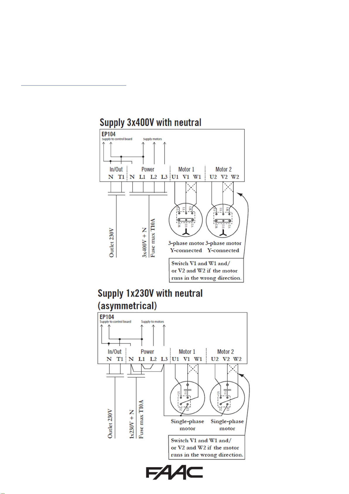
Set Power type in C202 to “0” for 3-Phase 400V with Neutral, or “2” for Single Phase with Neutral (Asymmetric).
Step 3 – Checking Motor Direction
To test the operation of the motor as we are in Service Mode, set L001 = 4 and set L002 = 0, this will allow
movement of only Motor 1. If you are using an EP104-1, please disregard L002.
At this point you should be able to use the Dead-Man Controls on the board itself (The three buttons below the
display, 1st Black is the Open, 2nd Black is Close) to move the gate in the desired direction. If the gate moves in the
opposite direction to the button being pressed, you need to switch the motor polarity as shown in the Power and
Motor Connections section above or double check L110 = 1 (Motor 1 on the left as viewed from inside) or 2 (Motor 1
on the right as viewed from inside). If you are using an EP104-2, repeat the process but set L001 = 0 and set L002 = 4
and perform the same test but now double check L120 = 1 (Motor 2 on the left as viewed from inside) or 2 (Motor 2
on the right as viewed from inside). Please only press the button for a second or so to check movement as otherwise
it is most likely that an Error will be generated, as have not yet set the power readings.
If it does not move, something is not wired correctly, check incoming voltage, motor connections first.
Step 4 – Motor Power and Encoder Settings
We can now adjust the power and encoder settings of the EP104. If you have a Single Leaf system, please skip to
(14). At this stage, the gates can be in any position, ideally halfway to start and engaged to the operator.
1. Set L001 = 0 and L002 = 4
2. Set C240 = 0.0
3. C241 (Motor Power Readout), it should say 0.00 with the gate stopped. Press and hold the Open Button on
the board and make a note of the value when the gate is moving and then press the Close Button on the
board and make a note of the value when gate is moving
4. Set C242 = average value recorded from C241 when opening plus 0.3
5. Set C243 = average value recorded from C241 when closing plus 0.3
6. C261 (Motor Current Readout), it should say 0.00 with the gate stopped. Press and hold the Open Button on
the board and make a note of the value when the gate is moving and then press the Close Button on the
board and make a note of the value when gate is moving
7. Set C262 = average value recorded from C261 when opening
8. Set C263 = average value recorded from C261 when closing
9. Set L002 = 1
10. Check L120 is set to either “1” if Motor 2 is on the Left or “2” if on the right (viewed from motor side)
11. L121 (Position Readout Motor 2). Press and hold the Open Button on the board until the gate is fully open
and make a note of the value. Now press the Close Button on the board and make a note of the value
12. Set L122 = value recorded from L121 when fully open
13. Set L123 = value recorded from L121 when fully closed
14. Set L002 = 0 and L001 = 4
15. Set C230 = 0.0

Page | 7
16. C231 (Motor Power Readout), it should say 0.00 with the gate stopped. Press and hold the Open Button on
the board and make a note of the value when the gate is moving and then press the Close Button on the
board and make a note of the value when gate is moving
17. Set C232 = average value recorded from C231 when opening plus 0.3
18. Set C233 = average value recorded from C231 when closing plus 0.3
19. C251 (Motor Current Readout), it should say 0.00 with the gate stopped. Press and hold the Open Button on
the board and make a note of the value when the gate is moving and then press the Close Button on the
board and make a note of the value when gate is moving
20. Set C252 = average value recorded from C261 when opening
21. Set C253 = average value recorded from C261 when closing
22. Set L001 = 1
23. Check L110 is set to either “1” if Motor 1 is on the Left or “2” if on the right (viewed from motor side)
24. L111 (Position Readout Motor 1). Press and hold the Open Button on the board until the gate is fully open
and make a note of the value. Now press the Close Button on the board and make a note of the value
25. Set L112 = value recorded from L111 when fully open
26. Set L113 = value recorded from L111 when fully closed
27. Set L002 = 1
At this stage, while the EP104 is in Service Mode, the Internal Open and Close Buttons will operate the gate/s in
Dead-Man Operation within the encoder settings set above.
Step 5 – Safety Edge Circuit
Wire in Safety Edges as shown below. Please note that the External Unit for personal protection is representing an
optional wireless Safety Edge Controller system.
If NO Safety edges are to be connected to the control board, please adjust the following parameters accordingly
otherwise it will not function correctly. (Page 36, 37)
NO SE.C1 Edge (Closing) – C111 = 0 (adjust to 2 if required)
NO SE.C2 Edge (Closing) – C121 = 0 (adjust to 2 if required)
NO SE.O1 Edge (Opening) – C131 = 0 (adjust to 2 if required)
NO SE.O2 Edge (opening) – C141 = 0 (adjust to 2 if required)
Step 6 – Take the EP104 out of Service Mode
Set C033 = 3. In this mode, the gate will function from the internal buttons and will operate in a single press to Open
fully with the Open Button and a single press to Close fully with the Close Button and all safeties active.

Page | 8
EP104 – Inputs and Automatic Closing
Inputs
The EP104-1 has 6 different inputs, as shown below.
Partial Openings
If only 1 gate is required to open in a double gate system from time to time, we would normally suggest using Input
3. The following settings will need to be adjusted to make it function in this method.
Set P360 = 1
Set P362 = 1
In this method only Motor 1 will open fully and close if automatic closing is enabled. If P362 is set to “2” then only
Motor 2 will open fully and close if automatic closing is enabled.
If you would like to enable partial opening of Motor 1 or/and Motor 2 from time to time, we would normally suggest
using Input 4 (if Input 3 is already in use above). The following settings will need to be adjusted to make it function in
this method.
Set P460 = 1
Set P462 = 1 if applicable to Motor 1 only, 2 if applicable to Motor 2 only or 3 if applicable to both Motors
Set P463 = 1
Set L116 = degree position where Motor 1 will stop (use L111 to see the reading in normal operation)
Set L126 = degree position where Motor 2 will stop (use L121 to see the reading in normal operation)
Automatic Closing
By default the EP104 operates by using Input Commands as shown in the diagram above and it is in a Pulse to Open
and Pulse to Close function. If Automatic Closing is required, please set the parameter below.
Set C500 = Automatic Closing time 0(minutes).00(seconds), i.e. 20 seconds pause time = 0.20
If you would like to set Parking Logic function whereby the Closing Safety Photocell will trigger a command to close
once activated and then cleared. You can also set a delay as per below from the Photocell trigger.
Set C351 = 1
Set C354 = 1 to close immediately or 2 to close only once gate is fully open
Set C510 = Delay before automatic closing 00(seconds), i.e. 20 seconds pause time = 20

Page | 9
EP104 – Outputs and Connecting a Lock
Outputs
The EP104 does not have any outputs natively. If an output is required to control traffic lights, control locks or
provide position indicators to a BMS on site, then the use of a DB407 Output Card is required. Please note that if you
are replacing a version 4.06 or below EP104, you will also require a new DB407 as the current control boards are not
compatible with the older versions of the DB401 (the original version of the output card). The DB407 is connected to
the EP104 and wired as shown below.
Please ensure that the EP104 is completely powered down before installation of the output card and that the
desired outputs are wired in as per the below, and then power the EP104 back on.
In general terms the DB407 is used to both connect a Magnetic Lock to the gate and/or connect a traffic light system.
Wiring a Magnetic Lock to a EP104
When it is being used to connect a Magnetic lock, we would recommend the use of o2 and i1 and run a separate
power supply positive to the Magnetic Lock through Output 2 relay (shown in the next page). This Output is already
pre-configured to be enabled in the closed position and disabled as soon as the gate gets a command to open.

Page | 10
Wiring a Traffic Light to a EP104
When it is being used to connect a Traffic Light, we would recommend the use of o5 and o6 and i3 and run a
separate power supply positive to the Traffic Light and you would switch the negative through the outputs as per
below. Magnetic Lock through Output 2 relay (shown in the next page). The following settings will need to be
adjusted to make it function in this method.
Set o500 = 1
Set o511 = 1
Set o512 = 1
Set o513 = 3
Set o600 = 1
Set o610 = 1

Page | 11
Common Errors and Troubleshooting
Troubleshooting
Other manuals for DAAB EP104
1
Table of contents
Other FAAC Gate Opener manuals