Faber Varda User manual

installation and Operating Instructions
electrical ambience heating
40 010 464
99 49
VARDA/NARVIK
IVAR
ALMA
OTHELLO

1
ENEN
TABLE OF CONTENTS
1. FOREWORD 2
2. INTRODUCTION 3
3. SAFETY PRECAUTIONS 4
4. INSTALLATION 6
4.1 Installation Instructions 6
4.2 Installation Space 6
4.3 Location and Minimum Free Space 6
5. OPERATION 7
5.1 Operation 7
5.2 Flame effect 8
5.3 eating unit 8
5.4 Thermostat operation 9
5.5 Thermal safety cut-out 9
6. CLEANING AND MAINTENANCE 10
6.1 Cleaning 10
6.2 Lamp replacement 10
DESCRIPTION OF THE STOVE
DIMENSIONS
fig. 1 Varda/Narvik
fig. 3 Alma
fig. 2 Othello
fig. 4 Ivar
A: ot air outlet grille
B: Ashpan flap, controls cover
C: Controls located on top canopy
behind door
D: Door
E: Fan heater concealed behind grille
F: Flame effect window
G: Fan heater grill
: Firebox door
K: Fan heater
253
754/654
820/720
796/696
12
692
500 330
750
550
960
400
565 385
500 335
700
fig. 5 Varda/Narvik
fig. 7 Alma
fig. 6 Othello
fig. 8 Ivar
A
C
B
D
E
F
G
B
B
K

3
EN
2
EN EN
2. INTRODUCTION
This instruction manual gives you information about the design,
operation and maintenance of your fire, as well as safety
precautions and environmental recommendations.
As you read this manual, you will quickly learn how to operate
your fire. You will also find information about the safety and
maintenance of the equipment.
Read the manual carefully before using your hearth and then
keep the manual in a safe place.
1. FOREWORD
This fire incorporates a flame effect which can be used with or
without heating, so that comforting effect may be enjoyed at
any time of the year. The flame effect is provided by low
wattage motors and two or three 40 watt lamps. Using the
flame effect on its own, therefore, requires little electricity.
The controls are concealed behind the 'ashpan' flap, control
cover. A choice of 900 W or 1800W thermostatically controlled
heat output is provided by the fan heater, which is concealed
behind the top grille.
VARDA and NARVIK are designed to be inset in a fireplace
opening.
IVAR, ALMA and OT ELLO are designed to be free standing and
are normally positioned against a wall.
This appliance complies with the CE directives.

5
EN
4
EN
- Do not leave young children unsupervised in the vicinity of the
heater.
- Do not use this heater in series with a thermal control, a
programme controller, a timer or any other device that
switches or the heater automatically, since a fire risk exists
when the heater is accidentally covered or displaced.
- Ensure that furniture, curtains or other combustible material
are positioned no closer than 1 metre from the heater.
- In the event of a fault unplug the heater.
- Although the heater complies with safety standards, we do not
recommend it's use on deep pile carpets or on long hair type
of rugs.
- The appliance must be positioned so that the plug is
accessible.
EN
3. SAFETY PRECAUTIONS
- ave the stove installed by a qualified installer in accordance
with local and national (fire safety) regulations.
- Ensure that all packaging items are removed (read any warning
labels carefully).
- Retain all packaging untill installation is complete.
- The heater must be used on an ~ 230V supply and the
voltage marked on the heater must correspond with the supply
voltage.
- Warning: This appliance must be earthed.
- When using electrical appliances, basic precautions should
always be followed to reduce the risk of fire, electricalshock,
and injury to persons, including the following:
- If the appliance is damaged, check immediatly with the
supplier before installation and operation.
- Do not use outdoors.
- Do not use in the immediate surroundings of a bath, shower
or swimming pool.
- Do not locate the heater immediatly below a fixed socket
outlet or connection box.
- Do not cover the heater. Do not place material or garments on
the heater, or obstruct the air circulation around the heater,
for instance by curtains or furnitue, as this could cause
overheating and a fire risk.

7
EN
6
EN
5. OPERATION
IMPORTANT REMOVE THE CARDBORD LINER
The cardboard liner secured the fuel effect in place while the
product was transported and should be removed after installation.
Retain the cardboard liner, this must be refitted in the event of
transporting the appliance. Follow the following instructions.
ALMA
1. Open Ashpan Flap.
2. Lift window upwards and outwards.
3. Fold the top corners of the cardboard liner inwards and
remove.
4. Slide the fuel effect in towards the mirrored glass.
5. Fit the door glass.
OT ELLO
1. Open door.
2. Lift out cardboard liner.
3. Slide the fuel effect in towards the mirrored glass.
55..11 OOPPEERRAATTIIOONN
VARDA/NARVIK/IVAR/ALMA
The controls are located behind the hinged
'ashpan' flap, control cover (fig. 11).
Connect the fire to your electricity supply.
OT ELLO
The controls are located on the top canopy
behind the door (fig. 12).
Connect the fire to your electricity supply.
4. INSTALLATION (Varda/Narvik)
4.1 INSTALLATION INSTRUCTIONS
ave the stove installed by a qualified installer in conformance
with national and local (fire safety) regulations.
Be sure that the chimney functions properly.
4.2 INSTALLATION SPACE
4.3 LOCATION AND MINIMUM FREE SPACE
Consult the installation instructions for the
installation of the stove.
The Varda and Narvik are supplied with two
brackets on both sides at the bottom.
Remove the ‘M8’ screw A from the rear bracket
B. Remove the right-hand screw of the 2 sheet-
metal screws. Adjust the height of the bracket
using the other sheet-metal screw in the slotted
hole C. You can use the front brackets D to
adjust the whole stove more precisely by turning
the M8 screw E.
652
253
754/654
820/720
796/696
12
595
692
A
C
B
fig. 9 Varda/Narvik
A: Set of screws 10 mm, adjustable
B: Minimum built-in height
C: Connection cable
D
EB
C A
fig. 10 Varda/Narvik
fig. 11
fig. 12

9
EN
8
EN
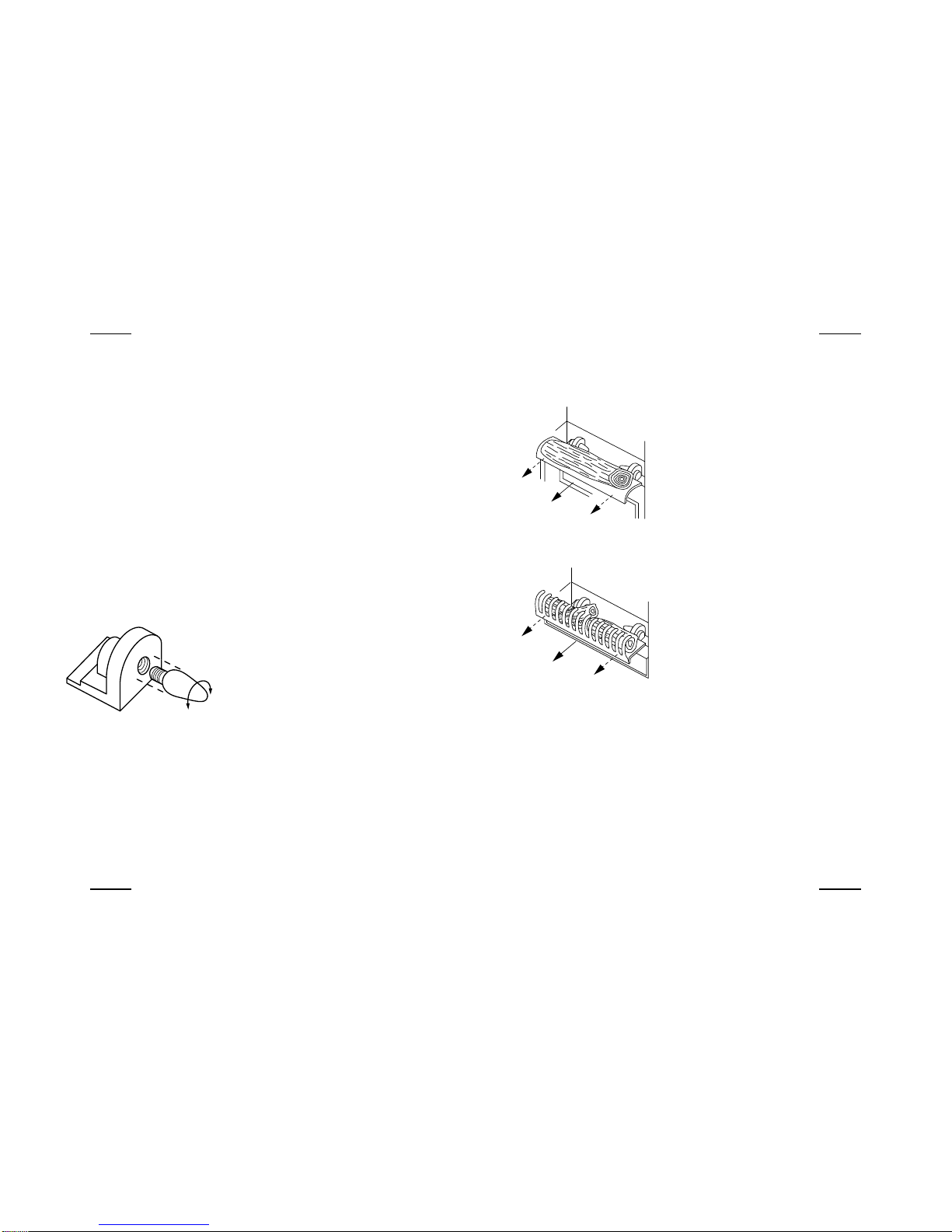
5.4 THERMOSTAT OPERATION
The thermostat controls the heat output according to the room
temperature. This ensures that the heater will not produce heat
unnecessary when the room is warm.
IVAR/ALMA
To set the temperature you require, turn the thermostat knob
fully clockwise to 'max' position. When the room is warm
enough, turn the knob back slowly until the thermostat just
clicks off. The heater will now maintain your selected
temperature (fig. 14).
Note: Once the thermostat has switched the appliance off it
may take some time before the heater comes back on. This
does not mean that the appliance is faulty.
VARDA/NARVIK/OT ELLO
The thermostat regulates the heat output according to user
needs. To set the temperature you require, turn the temperature
knob to position 3. If after a period of time you require more
heat turn the knob to position 3. If after a period of time you
require more heat turn the knob to a higher setting, or further
reductions in heat output may be obtained by turning the knob
to lower settings (fig. 15).
5.5 THERMAL SAFETY CUT-OUT
A thermal safety cut-out is incorporated in the heater to prevent
damage due to overheating. This can happen if the heat outlet
was restricted in any way. The heater will switch on once the
obstruction has been removed and the heater has cooled. If the
cut-out continues to operate intermittently, the heater should be
switched off and a service agent contacted.
5.2 FLAME EFFECT
Press Lswitch to the 'ON' position (a switch
is in the "ON" position when the red indicator
mark on the switch is visible). The flame effect
will now operate.
5.3 HEATING UNIT
You have a choice of low heat 900 W or high heat 1800 W
output. Both settings have thermostat temperature control. In
order to operate the heating, switch Lmust be in the 'ON'
position (see fig. 13).
5.3.1 Low eat Setting
With switch Lin the 'ON' position, press switch ' ' to 'ON'.
5.3.2 igh eat Setting
With switches Land ' ' in the 'ON' position, press Switch ' '
to 'ON'. The 1800W heat output is controlled by the thermostat,
which should be set to maximum (see 'thermostat operation').
m
i
n
m
a
x
e
c
o
n
0
16
5
43
2
fig. 13
fig. 14
fig. 15

11
EN
10
EN
IVAR/OT ELLO
To gain access to the lamps open the firebox
door. Remove the two screws securing the fuel
effect.
Remove the fuel assembly by lifting the logs
slightly and sliding out
Unscrew the defective lamp anti-clockwise.
Replace with a 230 V, 40 W E14 SES lamp, do
not over tighten. Refit fuel effect and close the
firebox door (fig. 17).
ALMA
To gain acces to the lamps open the ashpan
flap control cover. Lift the flame effect window
upwards and remove. Remove the fuel
assembly by lifting slightly and sliding out.
Unscrew the defective lamp anti-clockwise.
Replace with a 230 V, 40 W E14 SES lamp, do
not over tighten.
Refit fuel assembly and slide up against the
inner glass. Replace the flame effect window
(fig. 18).
6. CLEANING AND MAINTENANCE
Always disconnect from the power supply before attempting any
maintenance.
6.1 CLEANING
Before commencing cleaning, unplug the heater and allow it to
cool.
The surface of the heater should be given an occasional wipe
over with a soft damp cloth. Do not use detergents abrasive
cleaning powder or polish on the body of the heater. The glass
screen should be cleaned carefully with a chamois leather. Do
not use proprietary glass cleaners.
6.2 LAMP REPLACEMENT
VARDA/NARVIK
To gain acces to the lamps open the Ashpan
flap. Carefully slide out the lampholder tray.
Unscrew the defective lamp anti-clockwise.
Replace with a 230 V, 40 W E14 SES lamp, do
not over tighten (fig. 16).
Refit the lampholder tray.
Warning
fig. 16
fig. 17
fig. 18
This manual suits for next models
4
Table of contents
Other Faber Electric Heater manuals
Popular Electric Heater manuals by other brands

LIFESTYLE APPLIANCES
LIFESTYLE APPLIANCES 505-112 instruction manual

Sunbeam
Sunbeam SFH090 Instruction leaflet

Ashley
Ashley Miracle Heat operating instructions

Kambrook
Kambrook Optimum Radiant Heater KRH600 manual

Heatstore
Heatstore HSTR 90C Installation and operating instructions

Roberts Gorden
Roberts Gorden Combat UHA-150 Installation and operation