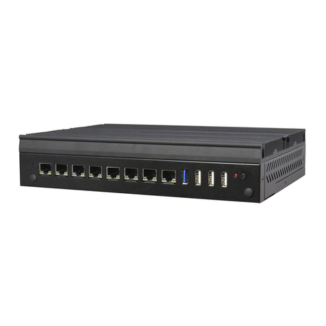
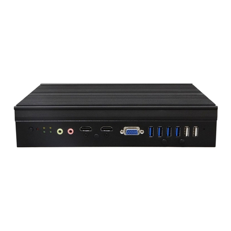
FabiaTech FX5503 User manual

ii
Copyright
©Copyright 2006FabIATech Corporation, The content of this publication may not
be reproduced in any part or as a whole, transcribed, stored in a retrieval system,
translated into any language, or transcribed in any form or by any means,
electronic, mechanical, and magnetic… or otherwise without the prior written
permission of FabiaTech Corporation.
Disclaimer
FabiaTech makes no representation of warranties with respect to the contents of
this publication. In an effort to continuously improve the product and add features,
FabiaTech reserves the right to revise the publication or change specifications
contained in it from time to time without prior notice of any kind from time to time.
FabiaTech shall not be reliable for technical or editorial errors or omissions, which
may occur in this document. FabiaTech shall not be reliable for any indirect,
special, incidental or consequential damages resulting from the furnishing,
performance, or use of this document.
Trademarks
Trademarks, brand names and products names mentioned in this publication are
used for identification purpose only and are the properties of their respective
owners.
Technical Support
If you have problems or difficulties in using the system or setting up the relevant
devices, and software that are not explained in this manual, please contact our
Returning Your Board For Service & Technical Support
If your board requires servicing, contact the dealer from whom you purchased the
product for service information. You can help assure efficient servicing of your
product by following these guidelines:
A list of your name, address, telephone, facsimile number, or email address
where you may be reached during the day
Description of you peripheral attachments
Description of your software (operating system, version, application
software, etc.) and BIOS configuration
Description of the symptoms (Extract wording any message)
For updated BIOS, drivers, manuals, or product information, please visit us at
www.fabiatech.com

iii
Table of Contents
Small Cube System....................................................................................................................i
Fanless Series..............................................................................................................................i
FX5503 User’s Manual..............................................................................................................i
Chapter 1 Introducing the FX5503 System................................................................................. 1
Overview ....................................................................................................................................1
Series Comparison Table.........................................................................................................2
Layout .........................................................................................................................................3
Specifications ............................................................................................................................4
Packing List.................................................................................................................................5
Chapter 2 Hardware Installation .................................................................................................7
Before Installation .....................................................................................................................7
Connecting the DC Power Jack, Power Switch.............................................8
LED Indicators (On the Front Panel)..................................................................8
Installing/Ejecting 2.5” HDD ................................................................................9
Connecting the Monitor, Keyboard, Mouse.................................................10
Connecting the COM1~COM4 ports .............................................................11
Connecting the LAN ports and USB Ports ......................................................11
Connecting the Audio Microphone In/ Speak Out.....................................12
Installing Compact Flash...................................................................................12
Installing Additional Memory: SoDIMM Socket For SDRAM Modules........13
Installing Mini PCI Card: Mini PCI Socket for WLAN Modules.....................14
Chapter 3 BIOS Setup.................................................................................................................. 17
Overview ..................................................................................................................................17
BIOS Functions...............................................................................................................18
Keyboard Convention ................................................................................................19
STANDARD CMOS SETUP........................................................................................................20
ADVANCED CMOS SETUP......................................................................................................22
ADVANCED CHIPSET SETUP...................................................................................................27
POWER MANAGEMENT..........................................................................................................30
PCI/PLUG AND PLAY...............................................................................................................32
PERIPHERAL SETUP ...................................................................................................................34

iv
Hardware Monitor Setup.......................................................................................................37
Password Setup.......................................................................................................................38
Chapter 4 Software Installation.................................................................................................. 39
VGA Drivers..............................................................................................................................39
WIN98_ME/WINXP_2K Driver.......................................................................................39
Audio Drivers............................................................................................................................40
WIN 98_ME/WINXP_2K Driver......................................................................................40
VIA 4 In 1 Driver .......................................................................................................................40
WIN 98/2000/XP Driver.................................................................................................40
LAN Utility & Driver...................................................................................................................41
Watchdog Timer.....................................................................................................................42
Watchdog Timer Setting.............................................................................................43
Watchdog Timer Enabled.................................................................................43
Watchdog Timer Trigger....................................................................................43
Watchdog Timer Disabled................................................................................43
Chapter5 Error Coding................................................................................................................ 45
Trouble Shooting for Post Beep and Error Messages........................................................45
Appendix...................................................................................................................................... 49
Dimension.................................................................................................................................49
Technical Reference..............................................................................................................50
Physical and Environmental.......................................................................................50
Serial Ports......................................................................................................................51
Parallel Ports..................................................................................................................55

v

FabIATech Corporation
1
Chapter1IntroducingtheFX5503System
Overview
The FX5503 is a compact size embedded system with low-power Pentium II grade
CPU module inside. This user’s manual provides information on the physical features,
installation, and BIOS setup of the FX5503.
Built to unleash the total potential of the Intel Ultra low power CPU, Able to support
650 MHz, this system supports dual 10Base-T/100Base-TX LAN ports, 256MB SDRAM,
2 USB ports, audio and a VGA controller.
Each FX5503 has four ports for I/O communications. Four RS-232C ports are
available.
The FX5503 is perfect for POS and POI applications, Internet Router, VPN Gateway,
fire wall, Mail Server, WBT, Thin Client and small Embedded Control. The unit is only
148.0mm (D) X 203.0mm (W) X 55.0mm (H).

FabIATech Corporation
2
SeriesComparisonTable
Model FX5503
Processor Intel (ULV) Power CPU-650Mhz
SO-DIMM (Max/Standard.) 512MB/ 256MB
CRT VGA Yes
Watchdog Timer Yes
Multi I/O Four RS232
Enhanced IDE One
USB 1.1 Two
Audio MIC-In/ Audio Out
RJ45 port (10/100Mbps) Two
IDE CF Socket One
Power Connector DC Jack
Dimensions (Unit: mm) 148(D) x 203(W) X 55(H)

FabIATech Corporation
3
2
3 4
~
1
Layout

FabIATech Corporation
4
Specifications
Processor Board –
650 MHz Intel Ultra low power CPU with 256MB SDRAM
I/O Outlets –
Two 100/10 base-TX Ethernet ports.
Four RS-232C Ports and two USB 1.1 ports.
One CRT and one PS/2 compatible keyboard/mouse interface.
One Audio MIC-In and one Audio Line-Out ear-jet connectors.
One DC-In plug connector with power switch.
One power LED, one HDD/CF access LED, and two LAN LEDs.
One mini-PCI socket for mini-PCI I/O modules.
Storage Bay-
One Compact Flash slot.
One 2.5" hard disk space.
Power requirement –
+12 ~ +24V DC with 15% tolerance, 18VA maximum.
Dimensions-
148.0mm(D) x 203.0mm(W) x 55.0mm(H)

FabIATech Corporation
5
PackingList
Upon receiving the package, verify the following things. Should any of the
mentioned happens, contact us for immediate service.
• Unpack and inspect the FX5503 package for possible damage that may
occur during the delivery process.
• Verify the accessories in the package according to the packing list and see
if there is anything missing or incorrect package is included.
• If the cable(s) you use to install the FX5503 is not supplied from us, please
make sure the specification of the cable(s) is compatible with the FX5503
system.
Note: after you install the FX5503, it is recommended that you keep the diskette or
CD that contains drivers and document files, and keep the document
copies, or unused cables in the carton for future use.
The following lists the accessories that may be included in your FX5503 package.
Some accessories are optional items that are only shipped upon order.
• One FX5503 embedded system.
• One AC to DC24V power adapter and 1 AC power code.
• One Y-type (3-terminal) PS/2 keyboard plus mouse port adapter cable.
• One COM port adapter cable.
• One pack of 2.5” hard disk installation guider with 4 fixed screws.
• One compact disc includes software utility.

FabIATech Corporation
6

FabIATech Corporation
7
Chapter2HardwareInstallation
This chapter introduces the system connectors & jumper settings, and guides you to
apply them for field application.
BeforeInstallation
Before you install the system, make sure you follow the following descriptions.
1. Before removing the cover, shut down the operation System and disconnect
power switch to off and unplug AC-to DC Adapter cable.
2. Install or unplug any connector, Compact Flash, and hard disk be sure that the
power is disconnected or power switch to off from the system. If not, this may
damage the system.
3. The ESD (Electricity Static Discharge) may be created from human body that
touches the board. It may do damage to the board circuit.

FabIATech Corporation
8
Connecting the DC Power Jack, Power Switch
Power is supplied through an external AC/DC power adapter. Check the technical
specification section for information about AC/DC power input voltage.
Since the switch does include a power switch, plugging its power adapter into a
power outlet then switch power to on, when you final installed system hardware
device.
LED Indicators (On the Front Panel)
The Power, LAN and HDD LED have two distinctive statuses: Off for inactive
operation and blinking light for activity.
DC +12V to +24V, 15% tolerance
22VA minimum
On: Power On
LED1: Power LED (Green)
LED2: HDD LED (Red)
LED3: LAN Access LED (Yellow)
LED4: LAN Access LED (Yellow)
4 3 2 1
Off: Power Off

FabIATech Corporation
9
Note:Use caution when handling the hard disk to prevent damage to IDE
connector as you insert hard disk. Gently slide the hard disk into the IDE and stop
when you feel resistance.
Installing/Ejecting 2.5” HDD
If you are installing hardware option, you can remove the front cover. The following
figure will guide you how to install 2.5" HDD inside the FX5503 and how to install the
FX5503 fixers.
Installing HDD
The following figure will guide you install fix support HDD and to inside the FX5503.
HDD

FabIATech Corporation
10
Ejecting HDD –Depend on Screwdriver
If you are removing HDD option, you can use I-type screwdriver or equivalent as
shown on right-down figure and push ahead to eject the hard disk with guiders
Connecting the Monitor, Keyboard, Mouse
Connect the monitor, keyboard and mouse to the FX5503 using the connections
provided on the backside of the chassis. See following figure and a side pictures.
1. A VGA connector is provided for CRT display
2. The connector uses the included adapter cable you can attach standard PS/2
type keyboard and mouse.Standard PS/2 keyboard can be plugged into this
connector without any adapter cable. If PS/2 keyboard and mouse will be used
simultaneously, a Y-type (3-terminal) adapter cable is needed.
Pin 1 Mouse Data
Pin 2 Keyboard Data
Pin 3 Ground
Pin 4 VCC
Pin 5 Mouse Clock
Pin 6 Keyboard Clock
DB15 Signal
1 Red
2 Green
3 Blue
13 Hsync
14 Vsync
12 DDC Data
15 DDC Clock
5 & 10 Digital Ground
6,7,8 Analog Ground
Others Not Used

FabIATech Corporation
11
Connecting the COM1~COM4 ports
Uses include COM port adapter cable to transfer to standard 9-pin female D-SUB
connector for COM3/COM4 ports
Connecting the LAN ports and USB Ports
The RJ45 connector with 2 LED’s for LAN. The left side LED (orange) indicates data is
being accessed and the right side LED (green) indicates on-line status. (On
indicates on-line and off indicates off-line)
The following lists the pin assignment of RJ45.
DB-9 RS-232 Signal
1 -DCD
6 -DSR
2 RXD
7 -RTS
3 -TXD
8 -CTS
4 -DTR
9 -RI
5 Ground
Case Case Ground
DB-9 RS-232 Signal
1 -DCD
6 -DSR
2 RXD
7 -RTS
3 -TXD
8 -CTS
4 -DTR
9 -RI
5 Ground
Case Case Ground
LAN Signal LAN Signal
1 TPTX+ 5 FBG1
2 TPTX - 6 TPRX -
3 TPRX+ 7 FBG2
4 FBG1 8 FBG2
1
8
RJ45 connector
(Front View)

FabIATech Corporation
12
Note: The Compact Flash socket (on the FX5503) supports 3.3V Compact Flash
and Micro Drives.
The FX5503 supports a dual port USB connector. Any USB device can be attached to
USB ports with plug-and-play supported. The left side port is USB #1 and the right side
port is USB #2
Connecting the Audio Microphone In/ Speak Out
Installing Compact Flash
If you are installing compact flash to the FX5503, See following figure and rear
pictures.
Line-Out
MIC-In
CF CARD

FabIATech Corporation
13
Installing Additional Memory: SoDIMM Socket For SDRAM Modules
You may extend additional memory to FX5503, remove the backside cover, See as
following figure and rear pictures.The DIMM socket supports 128MB to 512MB of
SDRAM modules.

FabIATech Corporation
14
Installing Mini PCI Card: Mini PCI Socket for WLAN Modules
You may extend additional mini PCI WLAN module to FX5503, remove the
backside cover, and See as following figure and backside pictures. Release the
screws on the bottom of the unit. (Please see the spots circled.)
Removing Backside Covers: Release the screws on the bottom
Release the Rear screws
The following figure will guide you how to release the rear screws.
2
3 4
~
1

FabIATech Corporation
15
Caution: Be very careful LED guide when handling and moving cover.
Removing Front/Top Covers: Release the screws
The following figure will guide you how to release the front screws
HARD DISK
Installing Mini PCI Card
Table of contents
Other FabiaTech Desktop manuals

FabiaTech
FabiaTech Fanless Series User manual

FabiaTech
FabiaTech FX5401 User manual

FabiaTech
FabiaTech FX5632 Series User manual

FabiaTech
FabiaTech FX5502 User manual

FabiaTech
FabiaTech FX5638 Series User manual

FabiaTech
FabiaTech FX5634 Fanless Series User manual

FabiaTech
FabiaTech FX5201 User manual

FabiaTech
FabiaTech FX5507 User manual

FabiaTech
FabiaTech FX5653 User manual

FabiaTech
FabiaTech FX5612 User manual