!
Drwg. No. 1643
13
exp
GB 230V SINGLE-PHASE PROGRAMMER FOR SWING GATE
OPERATORS
26
Line fuse
F1= 5A
DIP-SWITCH ON
OFF
1 456 7823
11 12 13 14 15
OUTPUT 24V 250mA for max. load:
- 2 pairs of photoelectric cells
- 1 Radio receiver
174 10
285
396
STOP NC
COMMON
OPEN NO
CLOSE NO
CONTACT NC
1
st
pair of PHOTOCELLS
RADIO NO
CONTACT NC
2
nd
pair of PHOTOCELLS
Indicator light 24V 3W max
Elpro 13 exp FADINI
COMMON
21
M1
SINGLE-PHASE
230V
MOTOR M1
M2
18
16 17 19 20
COMMON
SUPPORT FOR
PLUG-IN RADIO CARD
-
+
CLOSING LEAF
DELAY TIME
0s - 18s
L1 L6
L3 L4 L5
L2
COMMON
SAFETY NC CONTACT
24
22 23 25
FLASHING LIGHT
230V 25W max
230V ±10% 50Hz SINGLE-PHASE
POWER SUPPLY INPUT
12.5 μF
Capacitor
Motor M1
Line fuse
F2= 5A
Flashing light fuse
F3= 630mA
Transformer
fuse
F4= 630mA
Opening Delay
Relay
Closing Delay
Relay
Line relay
Motor M2
direction relay
230V – 24V
Transformer
28
26 27
-
+
DWELL TIME
0s - 120s
-
+
OPERATING TIME
2s - 100s
TERMINAL BOARD FOR
CONNECTING THE PULIN 3
BUTTON SWITCH
12V AC, 15VA POWER
SUPPLY OUTPUT
Fuse 24V
F5= 1A
12.5 μF
Capacitor
Motor M2
Motor M1
direction relay
SINGLE-PHASE
230V
MOTOR M2
ELECTRIC LOCK
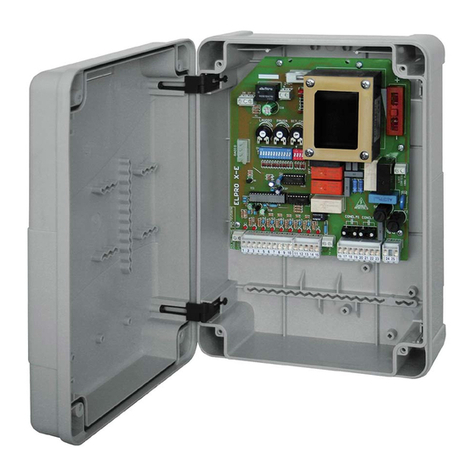
General description: The Elpro 13 exp is an electronic microprocessor programmer for controlling and managing single-phase gate openers fitted on swinging
gates. With its single-phase 50Hz 230V±10% power supply, it satisfies the Low Voltage 2006/95/CE and Electro Magnetic Compatibility regulations 2004/108/CE
- 92/31/CEE safety standards and should therefore be installed by a qualified technician in compliance with applicable regulations. Programmed operation
logic: automatic function, semi-automatic, pre-flashing, step-by-step by radio remote control, input for 2nd pair of photocells, electric lock output, pedestrian
opening function, stroke reversing pulse function, operator status indicator light.
The Manufacturer declines responsibility for improper use of the programmer and reserves the right to amend and update this manual and the programmer
without prior notice. Non-compliance with installation rules can cause serious damage to properties and people.
IMPORTANT:
- The programmer must be installed in a protected, dry place with its own protective case
- Apply a high sensitivity differential Thermo-magnet circuit breaker type 0.03 A to the programmer’s power supply
- Make sure that the electronic programmer has a 230V ±10% 50Hz power supply
- For power supply, flashing light use cable with wires with a section of 1.5 mm2 up to a distance of 50m; for Limitswitches and other accessories,
use cables with wires with 1mm2 sections.
- If the Photocells are not used, insert a jumper between terminals 1 and 2 and if the 2nd pair is not used, jumper the relative terminals
- If no Button switches or key switches without stop button are used, insert a jumper between terminals 3 and 6 NC contact
IF THE PROGRAMMER DOES NOT WORK:
- Ensure that the electronic programmer has a 230V ±10% power supply
- Ensure that the electric motor has a 230V ±10% power supply
- For distances of over 50 metres, increase the section of the wires.
- Check the single-phase 230V supply voltage
- Check the fuses
- Check all normally closed NC contacts of the programmer
- Check that there is no drop in voltage between the programmer and the electric motor
Diagnostic LEDs
L1= ON if the programmer is powered
L2= Photocell, normally ON, switches off with obstacle present
L3= Open, normally OFF, lights when Open pulse is received
L4= Close, normally OFF, lights when Close pulse is received
L5= Stop, normally ON, switches off when Stop impulse is given
L6= Radio, normally OFF, lights when Radio pulse is received
English
13
exp
230V SINGLE-PHASE PROGRAMMER FOR SWING GATE
OPERATORS
LOW VOLTAGE ELECTRICAL CONNECTIONS
DIP-SWITCH
1= ON 1st pair of Photocells stop gates during opening
2= ON Radio does not invert during opening
3= ON Closes in Automatic mode
4= ON Pre-flashing of flashing light
5= ON Step-by-step by radio with intermediate stop
6= ON Single pedestrian when gate is closed
7= ON Stroke reversing pulse function enabled when opening from closed gate position
8= ON Eliminates the Leaf Delay when opening. The motors start together
ON
OFF
1 456 7823
Radio contact:
- Open/Close (normal) changes direction at each
pulse
- Step-by-step with intermediate stop
Photocells:
12 13
12
OUTPUT 24Vac(MAX. LOAD:
2 pairs of PHOTOCELLS
1 RADIO RECEIVER)
1
DIP-SWITCH 1 (only for 1st pair of Photocells):
ON: Photocell stops gate on opening and changes direction
when closing once the obstacle has been removed
OFF: Photocell no stop on opening and changes direction
when closing in case of an obstacle
Pushbutton
switch:
2
ON: Does not change direction
during opening
OFF: Changes direction at each pulse
DIP-SWITCH 2:
ON: Step-by-step with intermediate stop
OFF: Normal operation
5
DIP-SWITCH 5:
NC CONTACT
1
st
pair of
PHOTOCELLS
NC CONTACT
2
nd
pair of
PHOTOCELLS
7
3
COMMON
RADIO NO
10
9
24V INDICATOR LIGHT
3W max
Electric lock:
Accessory that mechanically locks the gate in closed position, recommended
for installation with leaves over 1.80 m in length and non locking operators.
Operating time: power supply for 2 seconds, 100ms in advance before leaf
movement starts
11
8
COMMON
24V 3W Indicator light showing gate in movement:
Indicator light On = Gate open
Indicator light Off = Gate closed
0.5s flashing (fast)= closing movement
1s flashing= opening movement
3456
STOP NC
COMMON
OPEN NO
CLOSED NO
Safety contact:
14 15
SAFETY CONTACT NC
11 12 13 14 15
174 10
285
396
Microswitch on housing lid. If not
used, short-circuit terminals 14 and 15
The 1st pair of Photocells (device installed on gate posts) is managed by Dip-Switch 1
The 2nd pair of photocells (device installed inside entrance) stops gate during opening and changes gate direction when
closing once the obstacle has been removed
12V AC, 15VA OUTPUT
ELECTRIC LOCK POWER SUPPLY
GB
English
FADINI
FADINI
FADINI
Drwg. No. 1643
27
LOW VOLTAGE ELECTRICAL CONNECTIONS 11 12 13 14 15
17410
285396
English
13
exp
Drwg. No. 1643
27
230V SINGLE-PHASE PROGRAMMER FOR SWING GATE
OPERATORS
LOW VOLTAGE ELECTRICAL CONNECTIONS
DIP-SWITCH
1= ON 1st pair of Photocells stop gates during opening
2= ON Radio does not invert during opening
3= ON Closes in Automatic mode
4= ON Pre-flashing of flashing light
5= ON Step-by-step by radio with intermediate stop
6= ON Single pedestrian when gate is closed
7= ON Stroke reversing pulse function enabled when opening from closed gate position
8= ON Eliminates the Leaf Delay when opening. The motors start together
ON
OFF
1 456 7823
Radio contact:
- Open/Close (normal) changes direction at each
pulse
- Step-by-step with intermediate stop
Photocells
:
12 13
12
OUTPUT 24Vac(MAX. LOAD:
2 pairs of PHOTOCELLS
1 RADIO RECEIVER)
1
DIP-SWITCH 1 (only for 1st pair of Photocells):
ON: Photocell stops gate on opening and changes direction
when closing once the obstacle has been removed
OFF: Photocell no stop on opening and changes direction
when closing in case of an obstacle
Pushbutton
switch:
2
ON: Does not change direction
during opening
OFF: Changes direction at each pulse
DIP-SWITCH 2:
ON: Step-by-step with intermediate stop
OFF: Normal operation
5
DIP-SWITCH 5:
NC CONTACT
1
st
pair of
PHOTOCELLS
NC CONTACT
2
nd
pair of
PHOTOCELLS
7
3
COMMON
RADIO NO
10
9
24V INDICATOR LIGHT
3W max
Electric lock:
Accessory that mechanically locks the gate in closed position, recommended
for installation with leaves over 1.80 m in length and non locking operators.
Operating time: power supply for 2 seconds, 100ms in advance before leaf
movement starts
11
8
COMMON
24V 3W Indicator light showing gate in movement:
Indicator light On = Gate open
Indicator light Off = Gate closed
0.5s flashing (fast)= closing movement
1s flashing= opening movement
3456
STOP NC
COMMON
OPEN NO
CLOSED NO
Safety contact:
14 15
SAFETY CONTACT NC
11 12 13 14 15
174 10
285
396
Microswitch on housing lid. If not
used, short-circuit terminals 14 and 15
The 1st pair of Photocells (device installed on gate posts) is managed by Dip-Switch 1
The 2nd pair of photocells (device installed inside entrance) stops gate during opening and changes gate direction when
closing once the obstacle has been removed
12V AC, 15VA OUTPUT
ELECTRIC LOCK POWER SUPPLY
GB
English
FADINI
FADINI
FADINI
13
exp
Drwg. No. 1643
27
230V SINGLE-PHASE PROGRAMMER FOR SWING GATE
OPERATORS
LOW VOLTAGE ELECTRICAL CONNECTIONS
DIP-SWITCH
1= ON 1st pair of Photocells stop gates during opening
2= ON Radio does not invert during opening
3= ON Closes in Automatic mode
4= ON Pre-flashing of flashing light
5= ON Step-by-step by radio with intermediate stop
6= ON Single pedestrian when gate is closed
7= ON Stroke reversing pulse function enabled when opening from closed gate position
8= ON Eliminates the Leaf Delay when opening. The motors start together
ON
OFF
1 456 7823
Radio contact:
- Open/Close (normal) changes direction at each
pulse
- Step-by-step with intermediate stop
Photocells:
12 13
12
OUTPUT 24Vac(MAX. LOAD:
2 pairs of PHOTOCELLS
1 RADIO RECEIVER)
1
DIP-SWITCH 1 (only for 1st pair of Photocells):
ON: Photocell stops gate on opening and changes direction
when closing once the obstacle has been removed
OFF: Photocell no stop on opening and changes direction
when closing in case of an obstacle
Pushbutton
switch:
2
ON: Does not change direction
during opening
OFF: Changes direction at each pulse
DIP-SWITCH 2:
ON: Step-by-step with intermediate stop
OFF: Normal operation
5
DIP-SWITCH 5:
NC CONTACT
1
st
pair of
PHOTOCELLS
NC CONTACT
2
nd
pair of
PHOTOCELLS
7
3
COMMON
RADIO NO
10
9
24V INDICATOR LIGHT
3W max
Electric lock:
Accessory that mechanically locks the gate in closed position, recommended
for installation with leaves over 1.80 m in length and non locking operators.
Operating time: power supply for 2 seconds, 100ms in advance before leaf
movement starts
11
8
COMMON
24V 3W Indicator light showing gate in movement:
Indicator light On = Gate open
Indicator light Off = Gate closed
0.5s flashing (fast)= closing movement
1s flashing= opening movement
3456
STOP NC
COMMON
OPEN NO
CLOSED NO
Safety contact:
14 15
SAFETY CONTACT NC
11 12 13 14 15
174 10
285
396
Microswitch on housing lid. If not
used, short-circuit terminals 14 and 15
The 1st pair of Photocells (device installed on gate posts) is managed by Dip-Switch 1
The 2nd pair of photocells (device installed inside entrance) stops gate during opening and changes gate direction when
closing once the obstacle has been removed
12V AC, 15VA OUTPUT
ELECTRIC LOCK POWER SUPPLY
GB
English
FADINI
FADINI
FADINI
13
exp
Drwg. No. 1643
27
230V SINGLE-PHASE PROGRAMMER FOR SWING GATE
OPERATORS
LOW VOLTAGE ELECTRICAL CONNECTIONS
DIP-SWITCH
1= ON 1st pair of Photocells stop gates during opening
2= ON Radio does not invert during opening
3= ON Closes in Automatic mode
4= ON Pre-flashing of flashing light
5= ON Step-by-step by radio with intermediate stop
6= ON Single pedestrian when gate is closed
7= ON Stroke reversing pulse function enabled when opening from closed gate position
8= ON Eliminates the Leaf Delay when opening. The motors start together
ON
OFF
1 456 7823
Radio contact:
- Open/Close (normal) changes direction at each
pulse
- Step-by-step with intermediate stop
Photocells:
12 13
12
OUTPUT 24Vac(MAX. LOAD:
2 pairs of PHOTOCELLS
1 RADIO RECEIVER)
1
DIP-SWITCH 1 (only for 1st pair of Photocells):
ON: Photocell stops gate on opening and changes direction
when closing once the obstacle has been removed
OFF: Photocell no stop on opening and changes direction
when closing in case of an obstacle
Pushbutton
switch:
2
ON: Does not change direction
during opening
OFF: Changes direction at each pulse
DIP-SWITCH 2:
ON: Step-by-step with intermediate stop
OFF: Normal operation
5
DIP-SWITCH 5:
NC CONTACT
1
st
pair of
PHOTOCELLS
NC CONTACT
2
nd
pair of
PHOTOCELLS
7
3
COMMON
RADIO NO
10
9
24V INDICATOR LIGHT
3W max
Electric lock:
Accessory that mechanically locks the gate in closed position, recommended
for installation with leaves over 1.80 m in length and non locking operators.
Operating time: power supply for 2 seconds, 100ms in advance before leaf
movement starts
11
8
COMMON
24V 3W Indicator light showing gate in movement:
Indicator light On = Gate open
Indicator light Off = Gate closed
0.5s flashing (fast)= closing movement
1s flashing= opening movement
3456
STOP NC
COMMON
OPEN NO
CLOSED NO
Safety contact:
14 15
SAFETY CONTACT NC
11 12 13 14 15
174 10
285
396
Microswitch on housing lid. If not
used, short-circuit terminals 14 and 15
The 1st pair of Photocells (device installed on gate posts) is managed by Dip-Switch 1
The 2nd pair of photocells (device installed inside entrance) stops gate during opening and changes gate direction when
closing once the obstacle has been removed
12V AC, 15VA OUTPUT
ELECTRIC LOCK POWER SUPPLY
GB
English
FADINI
FADINI
FADINI
13
exp
Drwg. No. 1643
27
230V SINGLE-PHASE PROGRAMMER FOR SWING GATE
OPERATORS
LOW VOLTAGE ELECTRICAL CONNECTIONS
DIP-SWITCH
1= ON 1st pair of Photocells stop gates during opening
2= ON Radio does not invert during opening
3= ON Closes in Automatic mode
4= ON Pre-flashing of flashing light
5= ON Step-by-step by radio with intermediate stop
6= ON Single pedestrian when gate is closed
7= ON Stroke reversing pulse function enabled when opening from closed gate position
8= ON Eliminates the Leaf Delay when opening. The motors start together
ON
OFF
1 456 7823
Radio contact:
- Open/Close (normal) changes direction at each
pulse
- Step-by-step with intermediate stop
Photocells:
12 13
12
OUTPUT 24Vac(MAX. LOAD:
2 pairs of PHOTOCELLS
1 RADIO RECEIVER)
1
DIP-SWITCH 1 (only for 1st pair of Photocells):
ON: Photocell stops gate on opening and changes direction
when closing once the obstacle has been removed
OFF: Photocell no stop on opening and changes direction
when closing in case of an obstacle
Pushbutton
switch:
2
ON: Does not change direction
during opening
OFF: Changes direction at each pulse
DIP-SWITCH 2:
ON: Step-by-step with intermediate stop
OFF: Normal operation
5
DIP-SWITCH 5:
NC CONTACT
1
st
pair of
PHOTOCELLS
NC CONTACT
2
nd
pair of
PHOTOCELLS
7
3
COMMON
RADIO NO
10
9
24V INDICATOR LIGHT
3W max
Electric lock:
Accessory that mechanically locks the gate in closed position, recommended
for installation with leaves over 1.80 m in length and non locking operators.
Operating time: power supply for 2 seconds, 100ms in advance before leaf
movement starts
11
8
COMMON
24V 3W Indicator light showing gate in movement:
Indicator light On = Gate open
Indicator light Off = Gate closed
0.5s flashing (fast)= closing movement
1s flashing= opening movement
3456
STOP NC
COMMON
OPEN NO
CLOSED NO
Safety contact:
14 15
SAFETY CONTACT NC
11 12 13 14 15
174 10
285
396
Microswitch on housing lid. If not
used, short-circuit terminals 14 and 15
The 1st pair of Photocells (device installed on gate posts) is managed by Dip-Switch 1
The 2nd pair of photocells (device installed inside entrance) stops gate during opening and changes gate direction when
closing once the obstacle has been removed
12V AC, 15VA OUTPUT
ELECTRIC LOCK POWER SUPPLY
GB
English
FADINI
FADINI
FADINI
13
exp
Drwg. No. 1643
27
230V SINGLE-PHASE PROGRAMMER FOR SWING GATE
OPERATORS
LOW VOLTAGE ELECTRICAL CONNECTIONS
DIP-SWITCH
1= ON 1st pair of Photocells stop gates during opening
2= ON Radio does not invert during opening
3= ON Closes in Automatic mode
4= ON Pre-flashing of flashing light
5= ON Step-by-step by radio with intermediate stop
6= ON Single pedestrian when gate is closed
7= ON Stroke reversing pulse function enabled when opening from closed gate position
8= ON Eliminates the Leaf Delay when opening. The motors start together
ON
OFF
1 456 7823
Radio contact:
- Open/Close (normal) changes direction at each
pulse
- Step-by-step with intermediate stop
Photocells:
12 13
12
OUTPUT 24Vac(MAX. LOAD:
2 pairs of PHOTOCELLS
1 RADIO RECEIVER)
1
DIP-SWITCH 1 (only for 1st pair of Photocells):
ON: Photocell stops gate on opening and changes direction
when closing once the obstacle has been removed
OFF: Photocell no stop on opening and changes direction
when closing in case of an obstacle
Pushbutton
switch:
2
ON: Does not change direction
during opening
OFF: Changes direction at each pulse
DIP-SWITCH 2:
ON: Step-by-step with intermediate stop
OFF: Normal operation
5
DIP-SWITCH 5:
NC CONTACT
1
st
pair of
PHOTOCELLS
NC CONTACT
2
nd
pair of
PHOTOCELLS
7
3
COMMON
RADIO NO
10
9
24V INDICATOR LIGHT
3W max
Electric lock:
Accessory that mechanically locks the gate in closed position, recommended
for installation with leaves over 1.80 m in length and non locking operators.
Operating time: power supply for 2 seconds, 100ms in advance before leaf
movement starts
11
8
COMMON
24V 3W Indicator light showing gate in movement:
Indicator light On = Gate open
Indicator light Off = Gate closed
0.5s flashing (fast)= closing movement
1s flashing= opening movement
3456
STOP NC
COMMON
OPEN NO
CLOSED NO
Safety contact:
14 15
SAFETY CONTACT NC
11 12 13 14 15
174 10
285
396
Microswitch on housing lid. If not
used, short-circuit terminals 14 and 15
The 1st pair of Photocells (device installed on gate posts) is managed by Dip-Switch 1
The 2nd pair of photocells (device installed inside entrance) stops gate during opening and changes gate direction when
closing once the obstacle has been removed
12V AC, 15VA OUTPUT
ELECTRIC LOCK POWER SUPPLY
GB
English
FADINI
FADINI
FADINI