Fagor CNC 8055 User manual

CNC 8055
·MCO/TCO·
Operating manual
Ref.1402

This product uses the following source code, subject to the terms of the GPL license. The applications busybox V0.60.2;
dosfstools V2.9; linux-ftpd V0.17; ppp V2.4.0; utelnet V0.1.1. The librarygrx V2.4.4. The linux kernel V2.4.4. The linux boot
ppcboot V1.1.3. If you would like to have a CD copy of this source code sent to you, send 10 Euros to Fagor Automation
for shipping and handling.
All rights reserved. No part of this documentation may be transmitted,
transcribed, stored in a backup device or translated into another language
without Fagor Automation’s consent. Unauthorized copying or distributing of this
software is prohibited.
The information described in this manual may be subject to changes due to
technical modifications. Fagor Automation reserves the right to change the
contents of this manual without prior notice.
All the trade marks appearing in the manual belong to the corresponding owners.
The use of these marks by third parties for their own purpose could violate the
rights of the owners.
It is possible that CNC can execute more functions than those described in its
associated documentation; however, Fagor Automation does not guarantee the
validity of those applications. Therefore, except under the express permission
from Fagor Automation, any CNC application that is not described in the
documentation must be considered as "impossible". In any case, Fagor
Automation shall not be held responsible for any personal injuries or physical
damage caused or suffered by the CNC if it is used in any way other than as
explained in the related documentation.
The content of this manual and its validity for the product described here has been
verified. Even so, involuntary errors are possible, hence no absolute match is
guaranteed. However, the contents of this document are regularly checked and
updated implementing the necessary corrections in a later edition. We appreciate
your suggestions for improvement.
The examples described in this manual are for learning purposes. Before using
them in industrial applications, they must be properly adapted making sure that
the safety regulations are fully met.
DUAL-USE PRODUCTS
Products manufactured by FAGOR AUTOMATION since April 1st 2014 will
include "-MDU" in their identification if they are included on the list of dual-use
products according to regulation UE 428/2009 and require an export license
depending on destination.

Operating manual
CNC 8055
CNC 8055i
·MCO/TCO·
OPTION
·3·
INDEX
CHAPTER 1 GENERAL CONCEPTS
1.1 M/T and CO work mode................................................................................................... 5
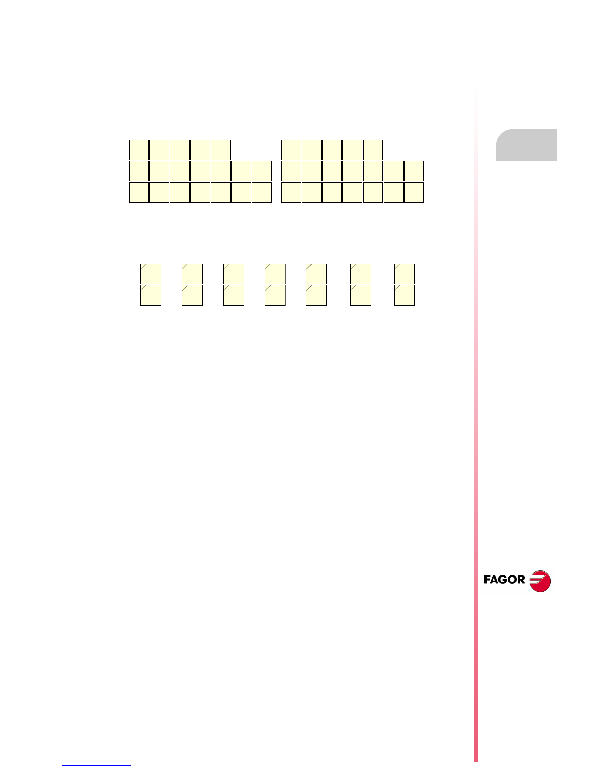
1.2 Keyboard.......................................................................................................................... 6
1.3 Keyboard customizing...................................................................................................... 9
CHAPTER 2 OPERATING IN JOG MODE
2.1 Introduction .................................................................................................................... 12
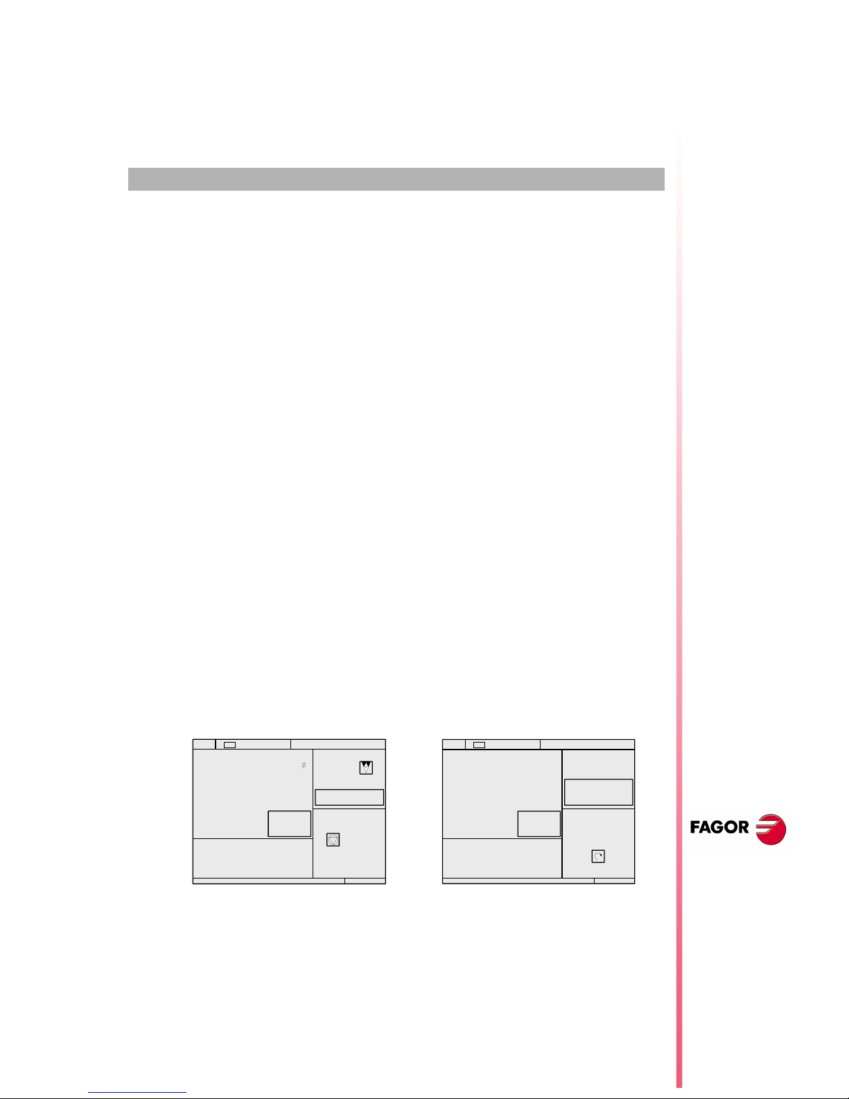
2.1.1 Standard screen of the CO mode. ............................................................................. 12
2.1.2 Auxiliary screen of the CO mode. .............................................................................. 14
2.2 Axis control .................................................................................................................... 16
2.2.1 Work units .................................................................................................................. 16
2.2.2 Coordinate preset....................................................................................................... 16
2.2.3 Managing the axis feedrate (F) .................................................................................. 16
2.3 Home search..................................................................................................................17
2.4 Jog movement ............................................................................................................... 18
2.4.1 Movement to the programmed coordinate ................................................................. 18
2.4.2 Incremental movement............................................................................................... 18
2.4.3 Continuous movement ............................................................................................... 19
2.4.4 Movement with an electronic handwheel ................................................................... 20
2.5 Tool control .................................................................................................................... 24
2.5.1 Single tool change point............................................................................................. 24
2.5.2 Variable tool change point.......................................................................................... 25
2.5.3 Live tool...................................................................................................................... 26
2.6 Spindle control ............................................................................................................... 28
2.6.1 Spindle in rpm ............................................................................................................ 29
2.6.2 Constant surface speed ............................................................................................. 30
2.7 ISO management........................................................................................................... 32
CHAPTER 3 WORKING WITH OPERATIONS OR CYCLES
3.1 Associated programs ..................................................................................................... 35
3.2 Associated subroutines.................................................................................................. 35
3.3 OEM cycles.................................................................................................................... 36
3.3.1 Define the screen ....................................................................................................... 36
3.3.2 Configuration file ........................................................................................................ 37
3.3.3 Associated subroutine................................................................................................ 41
3.3.4 Error log file (P999500) .............................................................................................. 43
3.4 Access to OEM cycles from the PLC ............................................................................. 44
3.5 Cycle data entry .............................................................................................................45
3.6 Simulation and execution............................................................................................... 46
3.7 Background cycle editing ............................................................................................... 46
3.8 Positioning cycle ............................................................................................................47
3.8.1 Definition of data ........................................................................................................ 48
3.8.2 Definition of spindle conditions................................................................................... 49
3.8.3 Definition of machining conditions.............................................................................. 49
CHAPTER 4 SAVING PROGRAMS
4.1 List of saved programs................................................................................................... 52
4.2 See the contents of a program....................................................................................... 53
4.2.1 See one of the cycles in detail ................................................................................... 53
4.3 Edit a new part-program ................................................................................................ 54
4.3.1 Saving an ISO block or a cycle .................................................................................. 54
4.4 Delete a new part program ............................................................................................ 55
4.5 Copying a part-program into another one ...................................................................... 55
4.6 Modify a part-program.................................................................................................... 56
4.6.1 Delete an operation.................................................................................................... 56
4.6.2 Move an operation to another position....................................................................... 56
4.6.3 Add or insert a new operation .................................................................................... 57
4.6.4 Modify an existing operation ...................................................................................... 57

·4·
Operating manual
CNC 8055
CNC 8055i
·MCO/TCO·
OPTION
CHAPTER 5 EXECUTION AND SIMULATION
5.1 Simulating or executing an operation or cycle ............................................................... 60
5.2 Simulating or executing a part-program......................................................................... 61
5.2.1 Simulating or executing a portion of a part-program .................................................. 61
5.3 Simulating or executing an operation that has been saved ........................................... 61
5.4 Execution mode ............................................................................................................. 62
5.4.1 Tool inspection........................................................................................................... 63
5.5 Graphic representation .................................................................................................. 64

·5·
1
CNC 8055
CNC 8055i
·MCO/TCO·
OPTION
GENERAL CONCEPTS
1.1 M/T and CO work mode
The CNC offers all the features of the M/T model plus those specific of the CO mode.
There are 2 work modes: M/T and CO work mode. This manual refers to the CO mode.
The M or T work mode described in the installation, Operation and Programming manuals will be
used for:
•Setup.
•Editing the PLC program.
•Screen customizing.
•Canned cycle customizing.
•Eliminating certain CNC errors.
•Etc.
The CO mode lets the machine manufacturer:
•Customize the keyboard.
•Change the CNC screens.
•Design the machining operations or canned cycles.
•Create screens for diagnosis, setup, CNC-PLC status information, etc.
This manual describes how to operate with the basic or standard Fagor features and it is up to the
OEM to document all the changes and new cycles defined by him.
On CNC power-up and after the keystroke sequence [SHIFT] [RESET], the CNC displays the
standard screen for the selected work mode.
With the keystroke sequence [SHIFT] [ESC] , it is possible to switch from CO mode to M/T mode
and vice versa.
The standard screen of the CO mode depends on the model:
To customize (modify or replace) this screen, refer to the "Screen customizing" chapter of the
installation manual.
TCO model MCO model
15:28:42 SBK P000002 IN POSITION
X
Z
S
00044.000
-00443.331
0
HOME X 0023.700
HOME Z -0009.578
U 00025.000
B 00000.013
C 00014.480
F 0100.000 % 080
T 02
S 0100
D 12
CHANGE POSITION
X 25.000 Z 85.000
% 115
SMAX 1000
RANGE 1
15:28:42 SBK P000002 IN POSITION
X
Z
S
00044.000
-00443.331
115
HOME X 0000.000
HOME Z 0000.000
U 00025.000
B 00000.013
C 00014.480
F00100.000 % 080
T 02
S 00100
D 12
CHANGE POSITION
Z 85.000
% 115
RANGE 1
YHOME Y 0000.000
-00443.331 X 25.000
Y 35.000

·6·
Operating manual
CNC 8055
CNC 8055i
1.
GENERAL CONCEPTS
·MCO/TCO·
OPTION
Keyboard
1.2 Keyboard
Alphanumeric keyboard and command keys
JOG keys
Specific keys of the CO model.
Select the X character.
Select the A character.
Select the R character.
These keys may be used for:
• Moving the axes of the machine.
• Governing the spindle.
• Modifying the feedrate of the axes and the spindle speed.
• Starting and stopping the execution.
These keys may be used for:
• Selecting and defining the machining operations.
• Govern the external devices.
• Select the graphic representation.
• Selecting the single block or automatic execution Mode.
FAGOR
C7
F7
C6
F6
C5
F5
C4
F4
C3
F3
C2
F2
C1
F1
C8 C9 C10 C11
LEVEL
CYCLE
HELP
i
PCALL
ISO
ZERO
GRAPHICSSINGLE
O1 O3 O5 O7 O9 O11 O13
O14O12O10O8O6O4O2
Y
E
4
G(
5
H)
6
I$
X
AR
7
BU
8
CV
9
DW
Z
J"
1
K'
2
L;
3
M:
F
NÑ
-
+=
0
0?
·
PSP
ALT
S
Q!SHIFT ]
T
*INS /<> [
ENTER
RECALL
P.PROG
CLEAR
ESC
RESET
+
-
STOP
SPINDLE
SPEED
%
100 10 1
100
10
1
1000
10000
JOG
0
2
4
10
20
30 40 50 60 70
80
90
100
110
120
FEED %
Y
E
4
G(
5
H)
6
I$
X
AR
7
BU
8
CV
9
DW
Z
J"
1
K'
2
L;
3
M:
F
NÑ
-
+=
0
0?
·
PSP
ALT
S
Q!SHIFT ]
T
*INS /<> [
ENTER
RECALL
P.PROG
CLEAR
ESC
RESET
X
AR
SHIFT
X
AR
X
AR
ALT
+
-
STOP
SPINDLE
SPEED
%
100 10 1
100
10
1
1000
10000
JOG
0
2
4
10
20
30 40 50 60 70
80
90
100
110
120
FEED %
FAGOR
C7
F7
C6
F6
C5
F5
C4
F4
C3
F3
C2
F2
C1
F1
C8 C9 C10 C11
LEVEL
CYCLE
HELP
i
PCALL
ISO
ZERO
GRAPHICSSINGLE
O1 O3 O5 O7 O9 O11 O1 3
O14O12O10O8O6O4O2

Operating manual
CNC 8055
CNC 8055i
GENERAL CONCEPTS
1.
·MCO/TCO·
OPTION
·7·
Keyboard
Keys related to operations or canned cycles:
[C1] gives access to cycle 1, [C2[ to cycle 2 and so on.
Each key may have up to 10 levels or variants that are selected with the [LEVEL CYCLE] key.
For example:
C1 => Cycle 1, +Level => Cycle 21, +Level => Cycle 41, ....
When pressing [C1] through [C11], the CNC recovers the last cycle (level) used in each group.
The OEM may set keys [C1] through [C11] by inserting printed strips behind the keyboard.
Keys that act like softkeys F1 through F7 in M/T mode:
Specific keys for the CO mode:
From left to right, they are used for:
•[ZERO]: Doing a home search.
•[POS.]: Executing the positioning cycle.
•[ISO]: ISO and MDI management.
•[PCALL]: To see the screens or cycles defined by the OEM.
•[HELP]: (for the M/T mode).
•
[TWO-COLOR]: Selecting various states in particular cycles or screens.
•[LEVEL CYCLE]: Selecting various levels in each cycle.
Free keys:
The OEM may set the free blank keys by inserting printed strips behind the keyboard. This
chapter describes how to manage those keys.
The [SINGLE] key lets execute or simulate step by step.
The [GRAPHICS] key lets simulate the cycle or see the tool movement graphics duration
execution.
Free keys, usually to control external devices:
The OEM may set them by inserting printed strips behind the keyboard.
This chapter describes how to manage those keys.
C7
F7
C6
F6
C5
F5
C4
F4
C3
F3
C2
F2
C1
F1
C8 C9 C10 C11
LEVEL
CYCLE
C7
F7
C6
F6
C5
F5
C4
F4
C3
F3
C2
F2
C1
F1
LEVEL
CYCLE
HELP
i
PCALL
ISO
ZERO
GR APHICS
SINGLE
O1 O3 O5 O7 O9 O11 O13
O14O12O10O8O6O4O2

·8·
Operating manual
CNC 8055
CNC 8055i
1.
GENERAL CONCEPTS
·MCO/TCO·
OPTION
Keyboard
Command keys:
Special keystroke sequences:
For the CNC to assume the edited value.
To extract saved data, cycles or blocks from memory.
To access program saving.
Depending on the data, it lets delete the last character inserted or the whole program.
To quit the selected operation, cycle or mode.
To toggle between CO and M/T modes.
To initialize the CNC. It is the same as turning the CNC off and back on.
It clears (blanks out) the CRT screen. Press any key to restore it.
ENTER
RECALL
P.PROG
CLEAR
ESC
SHIFT
ESC
RESET
SHIFT
CLEAR
SHIFT

Operating manual
CNC 8055
CNC 8055i
GENERAL CONCEPTS
1.
·MCO/TCO·
OPTION
·9·
Keyboard customizing
1.3 Keyboard customizing
The machine manufacturer must use the PLC program to activate and deactivate the external
devices.
The CNC will inform the PLC about the status of each key. The corresponding register bit will be
set to 1 when the key is pressed and 0 when it is not pressed.
The register bit for each key is:
Keys [O1] through [O14] have a lamp. The status of the lamp of each key must be controlled by the
machine manufacturer through the PLC program using the input variables TCLED* indicated in the
figure.
Examples:
The [O1] key is used to control the coolant.
DFU B28R561 = CPL TCLED1
= CPL O33
A number of conditions must be met in order to activate the device that may be activated and
deactivated with the [O2] key.
DFU B30R561 AND (Rest of conditions) = CPL TCLED2
= CPL O34
TCLED1 TCLED3 TCLED5 TCLED7 TCLED9 TCLED11 TCLED13
TCLED2 TCLED4 TCLED6 TCLED8 TCLED10 TCLED12 TCLED14
O1 O3 O5 O7 O9 O11 O13
O14O12O10O8O6O4O2
B26
R561
B27
R561
B0
R562
B1
R562
B31
R560
B28
R561
B29
R561
B2
R562
B3
R562
B30
R561
B31
R561
B4
R562
B5
R562
B7
R561
B6
R561
B5
R561
B15
R561
B14
R561
B13
R561
O1
O2
O3
O4
O5
O6
O7
O8
O9
O10
O11
O12
O13
O14

·10·
Operating manual
CNC 8055
CNC 8055i
1.
GENERAL CONCEPTS
·MCO/TCO·
OPTION
Keyboard customizing

·11·
2
CNC 8055
CNC 8055i
·MCO/TCO·
OPTION
OPERATING IN JOG MODE
The standard screen of the CO mode depends on the model:
The way to operate with either model is very similar. If any of the features described in this chapter
is not common to both models, it will clearly indicate which model it corresponds to.
When pressing the [TWO-COLOR] key, the CNC shows the auxiliary screen of the CO mode.
TCO model MCO model
15:28:42 SBK P000002 IN POSITION
X
Z
S
00044.000
-00443.331
0
HOME X 0023.700
HOME Z -0009.578
U 00025.000
B 00000.013
C 00014.480
F 0100.000 % 080
T 02
S 0100
D 12
CHANGE POSITION
X 25.000 Z 85.000
% 115
SMAX 1000
RANGE 1
15:28:42 SBK P000002 IN POSITION
X
Z
S
00044.000
-00443.331
115
HOME X 0000.000
HOME Z 0000.000
U 00025.000
B 00000.013
C 00014.480
F00100.000 % 080
T 02
S 00100
D 12
CHANGE POSITION
Z 85.000
% 115
RANGE 1
YHOME Y 0000.000
-00443.331 X 25.000
Y 35.000
C6
LEVE
CYC
ELP
i
GRSINGLE
15:28:42 SBK P000002 IN POSITION
M0
(MSG " " )
(IF P102 EQ 1 GOTO N10)
(IF P101 EQ 0 RET)
M3
(RET)
N10 M4
(RET)
G01 G18
M41
PARTC : 000000
CYTIME : 00:00:00:00
TIMER: : 000000:00:00
COMMAND
X 00020.000
Z 00089.520
C 00014.480
U 00025.000
THEORETICAL
ACTUAL
X 00020.000
Z 00089.520
C 00014.480
RPM M/MIN
TO GO
X 00000.000
Z 00000.000
C 00000.000
X 00000.000
Z 00000.000
C 00000.000
FOLLOWING ERROR
S 0.0000 S 0.0000 S 0.0000 S 0.0000
B 00000.013

·12·
Operating manual
CNC 8055
CNC 8055i
2.
OPERATING IN JOG MODE
·MCO/TCO·
OPTION
Introduction
2.1 Introduction
2.1.1 Standard screen of the CO mode.
The whole standard screen of the CO mode may be customized.
The one provided by Fagor contains the following information:
1. Clock.
2. This window may show the following data:
SBK When "Single Block" execution mode is selected.
DNC When the DNC mode is active.
P..... Number of the program currently selected.
Message «In position» - «Execution» - «Interrupted» - «RESET».
PLC messages.
3. This window shows the CNC messages.
4. This whole window may be customized.
The one provided by Fagor may show the following data:
•The coordinates of the axes. The Ø symbol indicates that the axis is working in diameter.
•If text 33 of program 999997 is defined, the CNC shows, in small characters, the coordinates
of the axes referred to machine reference zero.
•The real spindle rpm (S).
•In a frame, the coordinates of the auxiliary axes that have been defined.
15:28:42 SBK P000002 IN POSITION
X
Z
S
00044.000
-00443.331
0
HOME X 0023.700
HOME Z -0009.578
U 00025.000
B 00000.013
C 00014.480
F 0100.000 % 080
T 02
S 0100
D 12
CHANGE POSITION
X 25.000 Z 85.000
% 115
SMAX 1000
RANGE 1
T 02
S 00100
D 12
CHANGE POSITION
Z 85.000
% 115
RANGE 1
X 25.000
Y 35.000
12 3
4
5
6
7
98
6
7

Operating manual
CNC 8055
CNC 8055i
OPERATING IN JOG MODE
2.
·MCO/TCO·
OPTION
·13·
Introduction
5. This whole window may be customized.
The one provided by Fagor shows the axis feedrate «F» currently selected and the % of F being
applied.
When feed-hold is active, the color of the feedrate value changes.
Also, dependingn on the position of the left switch, it can show the following information.
6. This whole window may be customized.
The one provided by Fagor shows everything about the tool:
•In large characters, the number of the currently selected tool "T".
•The graphic representation for the location code (shape) associated with the tool (TCO
model).
•The "D" offset number associated with the tool. If the tool number and the offset number are
the same, the CNC will not show the "D" value.
•The position values (coordinates) of the tool change point referred to machine reference zero.
The CNC does not show this window when text 47 of program 999997 has not been defined.
7. This whole window may be customized.
The one provided by Fagor shows everything about the spindle:
•The selected theoretical turning speed. «S» value when working in rpm and «CSS» value
when working at constant surface speed in the TCO model.
•The spindle status. It is represented with an icon and may be turning clockwise,
counterclockwise or stopped.
•The % of spindle speed being applied.
•The maximum spindle rpm (TCO model).
•The active spindle speed gear (range). The CNC does not show this data when text 28 of
program 999997 has not been defined.
8. When accessing a work cycle, this window shows the help text associated with the selected icon.
That help text must be defined in program P999994 and edited in the desired language.
The format and considerations of program P999994 are described in detail in the chapter on
"General concepts".
9. Reserved.
10010 1
100
10
1
1000
10000
JOG
100 10 1
100
10
1
1000
10000
JOG
10010 1
100
10
1
1000
10000
JOG
100 10 1
100
10
1
1000
10000
JOG
10010 1
100
10
1
1000
10000
JOG
100 10 1
100
10
1
1000
10000
JOG
15:28:42 IN POSI TION
X
Z
S
00044.000
-00443.331
115
TO GO X 0000.000
TO GO Z 0000.000
F 0100.000 % 080
T 02
S 0100
% 115
SMAX 1000
RANGE 1
F 0100.000 % 080
x10
F 0100.000 % 080
100
F 0100.000 % 080

·14·
Operating manual
CNC 8055
CNC 8055i
2.
OPERATING IN JOG MODE
·MCO/TCO·
OPTION
Introduction
2.1.2 Auxiliary screen of the CO mode.
The whole auxiliary screen of the CO mode may be customized.
The one provided by Fagor contains the following information:
1. Clock.
2. This window may show the following data:
SBK When "Single Block" execution mode is selected.
DNC When the DNC mode is active.
P..... Number of the program currently selected.
Message «In position» - «Execution» - «Interrupted» - «RESET».
PLC messages.
3. This window shows the CNC messages.
4. This window shows the lines of the program currently selected.
5. The axes have the following fields:
COMMANDIt indicates the programmed coordinate or position that the axis must reach.
ACTUAL It indicates the actual (current) position of the axis.
TO GO It indicates the distance which is left to run to the programmed coordinate.
FOLLOWING ERRORDifference between the theoretical value and the real value of the
position.
The spindle (S) has the following fields:
THEORETICALProgrammed theoretical S speed.
RPM Speed in rpm.
M/MIN Speed in meters per minute.
FOLLOWING ERRORWhen working with spindle orientation (M19), it indicates the
difference between the theoretical and the real speeds.
The auxiliary axes only show the real current position of the axis.
15:28:42 SBK P000002 IN POSITION
M0
(MSG " " )
(IF P102 EQ 1 GOTO N10)
(IF P101 EQ 0 RET)
M3
(RET)
N10 M4
(RET)
G01 G18
M41
PARTC : 000000
CYTIME : 00:00:00:00
TIMER: : 000000:00:00
COMMAND
X 00020.000
Z 00089.520
C 00014.480
U 00025.000
THEORETICAL
ACTUAL
X 00020.000
Z 00089.520
C 00014.480
RPM M/MIN
TO GO
X 00000.000
Z 00000.000
C 00000.000
X 00000.000
Z 00000.000
C 00000.000
FOLLOWING ERROR
S 0.0000 S 0.0000 S 0.0000 S 0.0000
B 00000.013
12 3
4
5
6
87

Operating manual
CNC 8055
CNC 8055i
OPERATING IN JOG MODE
2.
·MCO/TCO·
OPTION
·15·
Introduction
6. This window shows the status of the «G, F, T, D, M» functions and the value of the variables.
PARTC It indicates the number of consecutive parts executed with the same part-
program.
Every time a new program is selected, this variable is reset to "0".
CYTIME It indicates the time elapsed while executing the part. It is given in "hours : minutes
: seconds : hundredths of a second".
Every time a part-program execution starts, even when repetitive, this variable is
reset to "0".
TIMER It indicates the count of the timer enabled by PLC. It is given in "hours : minutes
: seconds".
7. Reserved.
8. Reserved.
Selecting a program for simulation or execution
When the top center window shows the part-program selected next to the green [START] symbol,
the CNC acts as follows:
•If [START] is pressed, the CNC executes the part-program that is selected.
•If [CLEAR] is pressed, the CNC de-selects the part-program and removes it from the top center
window.
Symbol that appears in the middle of the top window when a part-program has been
selected for simulation or execution.
15:28:42
X
Z
S
00044.000
-00443.331
0
HOME X 0023.700
HOME Z -0009.578
U 00025.000
B 00000.013
C 00014.480
F 0100.000 % 080
T 02
S 0100
D 12
CHANGE POSITION
X 25.000 Z 85.000
% 115
SMAX 1000
RANGE 1
P000002 15:28:42
M0
(MSG " " )
(IF P102 EQ 1 GOTO N10)
(IF P101 EQ 0 RET)
M3
(RET)
N10 M4
(RET)
G01 G18
M41
PARTC : 000000
CYTIME : 00:00:00:00
TIMER: : 000000:00:00
COMMAND
X 00020.000
Z 00089.520
C 00014.480
U 00025.000
THEORETICAL
ACTUAL
X 00020.000
Z 00089.520
C 00014.480
RPM M/MIN
TO GO
X 00000.000
Z 00000.000
C 00000.000
X 00000.000
Z 00000.000
C 00000.000
FOLLOWING ERROR
S 0.0000 S 0.0000 S 0.0000 S 0.0000
B 00000.013
P000002

·16·
Operating manual
CNC 8055
CNC 8055i
2.
OPERATING IN JOG MODE
·MCO/TCO·
OPTION
Axis control
2.2 Axis control
2.2.1 Work units
When accessing the CO mode, the CNC assumes the work units "mm or inches", "radius or
diameter", "mm/min. or mm/rev", etc. selected by machine parameter.
To modify those values, access the M/T mode and change the corresponding machine parameter.
2.2.2 Coordinate preset
The coordinates must be preset on one axis at a time proceeding as follows:
[X] value [ENTER] [Z] value [ENTER]
The CNC requests confirmation of the command.
Pressing [ESC] quits the preset.
2.2.3 Managing the axis feedrate (F)
To set a particular axis feedrate value, proceed as follows:
[F] value [START].
Pressing [ESC] quits the selection.

Operating manual
CNC 8055
CNC 8055i
OPERATING IN JOG MODE
2.
·MCO/TCO·
OPTION
·17·
Home search
2.3 Home search
Home search may be done in 2 ways:
Homing all the axes
Homing a single axis
It executes the home search subroutine defined by the OEM in general
machine parameters P34 (REFPSUB).
The CNC keeps the part zero or zero offset that is active.
If the home search subroutine has not been defined, the CNC will display the
corresponding error message.
It homes the X axis.
It homes the Z axis.
The CNC will not maintain the part zero or zero offset active at the time and
assumes the machine reference zero as the new part zero.
ZERO
X
AR
ZERO
Z
J"
ZERO

·18·
Operating manual
CNC 8055
CNC 8055i
2.
OPERATING IN JOG MODE
·MCO/TCO·
OPTION
Jog movement
2.4 Jog movement
The axes of the machine can move as follows:
•Movement to the programmed coordinate.
•Incremental move.
•Continuous movement.
•Movement with an electronic handwheel.
2.4.1 Movement to the programmed coordinate
The axes move one by one. With the feedrate «F» and % currently selected.
[X] Coordinate [START] [Z] Coordinate [START]
2.4.2 Incremental movement
Turn the JOG switch to one of the incremental jog positions.
JOG
The incremental movement must be made one axis at a time. To do that, press
the JOG keys for the direction of the axis to be jogged.
Every time a key is pressed, the corresponding axis moves the amount set
by the switch. This movement is made at the selected feedrate «F».
Switch position Distance
1
10
100
1000
10000
0.001 mm or 0.0001 inches
0.010 mm or 0.0010 inches
0.100 mm or 0.0100 inches
1.000 mm or 0.1000 inches
10.000 mm or 1.0000 inches
100 10 1
100
10
1
1000
10000
JOG
100 10 1
100
10
1
1000
10000
JOG

Operating manual
CNC 8055
CNC 8055i
OPERATING IN JOG MODE
2.
·MCO/TCO·
OPTION
·19·
Jog movement
2.4.3 Continuous movement
Depending on the value assigned to general logic input "LATCHM", the movement will be carried
out in one of the following ways:
•The axis will move only while the corresponding jog key is kept pressed.
•The axis will start moving from the moment the JOG key is pressed until the same is pressed
again, or another JOG key is pressed. In this case, the movement will be transferred to that
indicated by the new key.
The following cases are possible when working with "F" in mm/rev:
A. The spindle is turning clockwise or counterclockwise.
The CNC moves the axes at the programmed F.
B. The spindle is stopped, but a spindle speed S has been selected.
Feature available at the TCO model when working in G95.
The CNC calculates the feedrate F in mm/min for the theoretical S and moves the axis.
For example if «F 2.000» and «S 500»:
Feedrate = F (mm/rev) x S (rev/min) = 2 x 500 = 1000 mm/min.
The axis moves at a feedrate of 1000 mm/min.
C. The spindle is stopped and no spindle speed S has been selected.
Feature available at the TCO model when working in G95.
The machine does not move, only with rapid movements. When pressingthe rapid key and the
corresponding axis key.
Place the left switch in the continuous-jog position and select at the right switch the
percentage (0% to 120%) of the feedrate to be applied.
The continuous jog must be made one axis at a time. To do that, press the
JOG keys for the direction of the axis to be jogged.
The axis moves at a feedrate equal to the selected percentage (0% to 120%)
of feedrate «F».
If while jogging an axis, this key is pressed (rapid), the axis will move at the maximum
feedrate possible, set by axis machine parameter "G00FEED". This feedrate will be
applied while the key is kept pressed and the previous feedrate will be restored when that
key is released.
100 10 1
100
10
1
1000
10000
JOG
10010 1
100
10
1
1000
10000
JOG
0
2
4
10
20
30 40 50 60 70
80
90
100
110
120
FEED %
0
2
4
10
20
30 40 50 60 70
80
90
100
110
120
FEED %

·20·
Operating manual
CNC 8055
CNC 8055i
2.
OPERATING IN JOG MODE
·MCO/TCO·
OPTION
Jog movement
2.4.4 Movement with an electronic handwheel
To move any of them, turn the switch to any of the handwheel positions.
Positions 1, 10 and 100 indicate the multiplying factor being applied besides the internal x4 to the
feedback pulses supplied by the electronic handwheel.
For example, if the manufacturer has set a distance of 0.100 mm or 0.0100 inches per handwheel
turn, thus:
There are 3 operating modes with handwheels:
Standard handwheel:
With the general handwheel, select the axis to be moved and turn the handwheel.
With individual handwheels, turn the handwheel associated with the axis to be moved.
"Path handwheel" mode:
For chamfering and rounding corners.
2 axes are moved along a selected path (chamfer or rounding) by moving a single handwheel.
This feature must be managed from the PLC.
The general handwheel is assumed as the "path handwheel" or the individual handwheel
associated with the X axis (MCO model) or Z (TCO model).
"Feed handwheel" mode:
To control the feedrate of the machine.
This feature must be managed from the PLC.
The various handwheel configurations are:
General handwheel: It can be used to jog any axis one by one.
Select the axis and turn the handwheel to move it.
Individual handwheel:It replaces the mechanical handwheels.
Up to 3 handwheels can be used (one per axis).
It only moves the axis it is associated with.
Switch position Distance
1
10
100
0.100 mm or 0.0100 inches
1.000 mm or 0.1000 inches
10.000 mm or 1.0000 inches
When jogging with individual handwheels, it may happen that depending on the
turning speed and the selector switch position, the CNC be demanded a faster
feedrate than the maximum allowed. The CNC will move the axis the indicated
distance but at the maximum feedrate allowed.
100 10 1
100
10
1
1000
10000
JOG
100 10 1
100
10
1
1000
10000
JOG
Other manuals for CNC 8055
4
This manual suits for next models
1
Table of contents
Other Fagor Control Unit manuals