Fagor CNC 8070 User manual

Quick reference
(SOFT 03.1X)(REF. 0706)
CNC 8070

Quick reference
(SOFT 03.1X)
INDEX
Screen description 1
Description of the keys 2
Manual (jog) mode 4
MDI mode 7
Automatic mode 8
Editing - simulation mode 10
List of "G" functions 11
List of "M" functions 13
Technological functions 14
Milling canned cycles. 15
Turning canned cycles 18
Probing canned cycles (milling) 25
Probing canned cycles (lathe) 30
Multiple machining (milling) 32
High level language 35
Operators and functions 39
User tables 40
Utilities 41

Quick reference
(SOFT 03.1X)1
SCREEN DESCRIPTION
General description of the work-mode screen
A. General CNC-status bar.
B. Screen for the active work mode.
C. Vertical softkey menu.
D. Horizontal softkey menu.
Detailed description of the CNC status bar
A. Icon (customizable) identifying the manufacturer.
B. Icon showing the status of the program of the active channel:
C. Program selected in the active channel for execution.
D. Number of the block in execution. The bottom icon indicates that the Single-block execution mode is active.
E. Information about the channels.
F. Active work mode (automatic, manual, etc.) selected screen number and total number of screens available.
G. Active CNC message.
H. PLC messages.
Turning the CNC off
[ALT] + [F4] Turn the CNC off.
A
C
B
D
A B C D E F
G H

Quick reference
2(SOFT 03.1X)
DESCRIPTION OF THE KEYS
Work modes
Automatic mode. [CTRL] + [F6]
Jog mode. [CTRL] + [F7]
MDI mode. [CTRL] + [F8]
Editing - simulation mode. [CTRL] + [F9]
User tables. [CTRL] + [F10]
Tool and magazine table. [CTRL] + [F11]
Utilities mode. [CTRL] + [F12]
Configurable mode. It may be configured using machine parameter "USERKEY".
To show the modes window. [CTRL] + [A]
Using the screens
Previous menu. [CTRL]+[F1]
Switch window. [CTRL]+[F2]
Key that may be customized by machine parameter. [CTRL]+[F3]
Help
It accesses the CNC's system help.
Execution keys
Cycle start key [START]. [CTRL]+[S]
Cycle stop key [STOP]. [CTRL]+[P]
RESET key. [CTRL]+[R]
"Single block" execution key. [CTRL]+[B]
Home search.
HELP
?
RESET
ZERO

Quick reference
(SOFT 03.1X)3
Alphanumeric keyboard
Delete character (It deletes the character to the left of the cursor).
Deleted character.
Insert / overwrite.
Ta b .
Escape key.
Command validation.
[RECALL] key. [CTRL]+[F5]
Feed selectors
Jog move type selector. Feedrate override % selector.
Operations in the user interface
[CTRL] + [W] Minimize/Maximize the CNC.
[CTRL] + [J] Show / hide the virtual operator panel.
[CTRL] + [M] Show / hide the PLC message list.
[CTRL] + [O] Show / hide the CNC message list.
[CTRL] + [K] Show / hide the calculator.
[ALT] + [S] Show / hide the channel synchronization window.
Program editor
[CTRL]+[TAB] Toggle between the editor and the error window.
[CTRL]+[C] Copy the selected text onto the clipboard.
[CTRL]+[X] Cut the selected text.
[CTRL]+[V] Paste the text that was "copied" or "cut".
[CTRL]+[Z] Undo the last change.
[CTRL]+[G] Save the program/Recover the original program.
[CTRL]+[HOME] Move the cursor to the beginning of the program.
[CTRL]+[END] Move the program to the end of the program.
SUP
INS
ESC
ENTER
RECALL
10010 10100
11
1000
10000
JOG
FEED
%
0
2
4
10
20
30
40
50
60
70 80 90 100
110
120
130
140
150
160
170
180
190
200

Quick reference
4(SOFT 03.1X)
MANUAL (JOG) MODE
JOG keys
The following keys may vary depending on the machine and the keyboard being used:
Jogging the axis in the positive direction.
Jogging the axis in the negative direction.
Rapid jogging of the axis.
Axis selection.
Selection of the moving direction.
Home search
Manual (this operation will cancel the current part zero):
Select the axis to be homed (using the alphanumeric keyboard).
Press the home-search key.
Press [START] to carry out a home search.
Press [ESC] to cancel the operation.
Automatic:
Press the home-search key.
Press [START] to carry out a home search.
Press [ESC] to cancel the operation.
Coordinate preset
Select the axis to be preset (using the alphanumeric keyboard).
Key in the desired preset value.
Press [ENTER] to preset the entered value.
Press [ESC] to cancel the operation.
Programmed movement:
Select the axis to be moved.
Enter the coordinate of the target point.
Press [START] to make the move.
Press [ESC] to cancel the operation.
X 7
X 7
X7
X Y Z
ZERO
ESC
ZERO
ESC
X Y Z
ESC
ENTER
X Y Z
ESC

Quick reference
(SOFT 03.1X)5
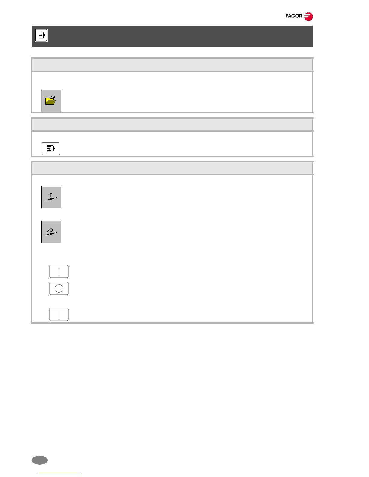
Movement of the axes
Manual movement (jogging) of the axes using JOG:
Continuous jog, (the axis moves while acting on the keyboard).
Turn the jog-type selector switch of the operator panel to the continuous jog position on
the dial.
Jog the desired axis using the JOG panel (keypad).
Incremental jog, (the axis moves a specific distance every time the operator acts on the keyboard).
Turn the jog selector switch of the operator panel to one of the incremental jog positions.
Jog the desired axis using the JOG panel (keypad).
Jogging the axes with handwheels:
Electronic handwheels may be used to move the axes.
Turn the jog selector switch of the operator panel to one of the handwheel positions.
Once the desired resolution has been selected and depending on the type of handwheel being used, general
or individual, proceed as follows:
1. General handwheel (may be used to jog any axis of the machine):
On the JOG keyboard, press one of the keys for the axis to be jogged. If several axes are selected
simultaneously, they all move at the same time. The CNC moves each axis as the handwheel is turned
depending on the setting of the selector switch and on the turning direction of the handwheel.
2. Individual handwheel (it is associated with a particular axis):
The CNC moves each axis as its relevant handwheel is turned depending on the setting of the selector
switch and on the turning direction of the handwheel.
Definition of machining conditions
Press the [S] key to select a spindle speed.
Press the [F] key to select a feedrate.
Enter the desired spindle speed or feedrate.
Press [START] to assume the entered value.
Press [ESC] to cancel the operation.
Spindle control
It is recommended to set the spindle turning speed (using the MDI mode) before selecting the turning direction.
Starts the spindle clockwise at the active speed.
Starts the spindle counterclockwise at the active speed.
To stop the spindle.
Spindle override (it may be used to vary the spindle turning direction).
Spindle orientation (it orients the spindle).
10010 10100
11
1000
10000
JOG
10010 10100
11
1000
10000
JOG
10010 10100
11
1000
10000
JOG
ESC

Quick reference
6(SOFT 03.1X)
Tool selection and tool change
Press the [T] key.
Key in the number of the tool to be placed in the spindle.
Press [START] to carry out the tool change.
Press [ESC] to cancel the operation.
Tool calibration
This operation is accessed with the "tool calibration" softkey.
The screen switching key may be used to select the calibration mode (with probe / without probe).
Press [ESC] to quit this mode.
Data definition:
Place the cursor over the relevant data, key in the desired value and press [ENTER].
1. Tool calibration without a probe:
It may be used to calibrate the length (L) of the tool that is currently at the spindle.
The radius (R) must be defined directly. To calibrate the length, follow these steps:
• Define the Z coordinate of the part used for calibration.
• Select the tool and the offset.
The CNC places the tool into the spindle and shows the dimensions defined in the tool table
for that offset.
• Use the MDI mode to start the spindle.
• Approach the tool manually until it touches the part.
Press the "Calibration" softkey.
2. Tool calibration with probe (only when using a table-top probe installed on the machine):
It may be used to calibrate the length (L) or the radius (R) of the tool that is currently in the spindle.
To calibrate, follow these steps:
• Define the probing distance and feedrate.
• Select the tool and the offset.
The shows the dimensions defined in the tool table for that offset.
The CNC places the tool into the spindle and shows the dimensions defined in the tool table
for that offset.
• Select the axis and the probing direction on the softkey menu.
• Use the MDI mode to start the spindle.
The tool moves along the selected axis and direction until touching the probe.
T
ESC
ESC
ENTER
ENTER

Quick reference
(SOFT 03.1X)7
Automatic loading of zero offsets or fixture offset tables
The CNC shows the list of available zero offsets and fixture offsets.
Select the zero offset or fixture offset where you wish to save the active offset.
Press [ENTER] to enter the offset in the table.
Press [ESC] to cancel the operation at any time.
Note: For the CNC to assume one of the stored zero offsets or fixture offsets, execute, in MDI mode, the function
G54, G55, ... , G59 or G159 associated with it.
MDI MODE
The MDI mode may be used in any work mode.
Operations in MDI mode
The following operations are possible in this MDI work mode:
• Edit and execute individual blocks.
• Save the set of blocks executed as an independent program.
Standard MDI window:
It is possible to edit and execute new blocks or recover blocks saved in the block history, which may be modified
before executing them.
• Editing:
The blocks may be edited directly on the edit line or may be recalled from the block history.
To access the history and select a block.
To accept the selection and show the block on the edit line.
To cancel the selection and quit the MDI mode.
• Execution:
Press [START] to execute currently displayed on the editing line.
Press [STOP] to interrupt the execution of the block.
Press [START] to resume execution.
Press [RESET] to cancel the execution of the block and perform a general reset of the CNC to
its initial conditions.
ENTER
ESC
ENTER
ESC
RESET

Quick reference
8(SOFT 03.1X)
AUTOMATIC MODE
Program selection
A different program may be selected and executed in each channel. The program is executed in the channel where
it is selected from.
To select a program, press the softkey "Select program" of the softkey menu and the CNC will show
a list of all the programs available.
Single-block execution mode
When this mode is active, the execution of the program is interrupted at the end of each block.
It selects the single block execution mode.
Tool inspection
This option is only available when the running program has been interrupted.
Press the relevant key to start the tool inspection.
Reposition the axes and the spindle:
To end tool inspection and reposition the spindle and the axes at the point where tool inspection began,
press the relevant softkey.
After pressing this softkey, the CNC will show a list of the axes that are out of position.
• Reposition the axes:
Select the axes with the relevant softkey.
Press [START] to perform the repositioning.
Press [STOP] to interrupt the repositioning and select other axes.
• Restore the spindle turning direction:
Select the relevant softkey.
Press [START] to restore the turning direction.

Quick reference
(SOFT 03.1X)9
Block search
This option may ver used to resume the execution of a program from the point where it was interrupted or aborted.
The CNC shows the options available for selecting the stop condition.
It returns to the main menu.
• Stop block:
It sets as the last block for program history recovery the one currently selected with the cursor.
• To select a subroutine from the list:
Select the folder containing the subroutine.
Select the program containing the subroutine or write its name in the bottom window.
Press [ENTER] to open the program.
Press [ESC] to cancel the selection and close the list of programs.
• Number of times:
It sets as stop condition, that the block selected as the stop block has been executed a specific number of times.
Enter the number of times.
Press [ENTER] to accept the value.
Press [ESC] to reject the value.
• Automatic search:
With this option, it is possible to recover the program history up to the block where the execution was interrupted.
• Starting block:
It establishes the block currently selected with the cursor as the first block of the block search.
There are two ways to select the block:
• Using the cursor
• Using the options "Text search" or "go to line" of the softkey menu.
ENTER ESC
ENTER
ESC

Quick reference
10 (SOFT 03.1X)
EDITING - SIMULATION MODE
Open the program to be edited
To select a program for the editing - simulation mode. This program may be a new one or an existing one. A different
program may be edited and executed in each channel.
To select a program from the list:
Select the folder that contains the program. If a new program is selected, it will be saved in this folder.
Select the program from the list or write its name in the bottom window. To edit a new program, write the name
of the program in the bottom window.
Press [ENTER] to accept the selection and open the program.
Press [ESC] to cancel the selection and close the list of programs.
Program simulation
The graphic window shows the program selected at the editing window and its name appears at the bottom center
of the screen.
The program simulation procedure is the following:
Choose the type of graphic representation, its dimensions and the point of view.
Activate the desired simulation options using the softkey menu.
Press the [START] softkey to start the simulation.
Press the [STOP] softkey to interrupt the simulation.
Press the [RESET] softkey to cancel the simulation.
"Single block" mode of simulation:
It selects the single-block mode using the relevant softkey.
It may be selected before or while simulating the program.
In this mode, the program is interrupted at the end of each block.
Press the [START] softkey to continue.
Simulation options:
The available simulation options are accessed from the softkey menu.
Pressing the softkey displays a window that shows the following options:
Tool radius compensation. Conditional stop during simulation.
Software limits. Block skip.
ENTER ESC

Quick reference
(SOFT 03.1X)11
LIST OF "G" FUNCTIONS
M The function is modal.
D By default, this function is active
?: The initial value depends on the machine parameter.
V This function is displayed in the G-code history.
Function M D V Meaning
G00 * ? * Rapid traverse
G01 * ? * Linear interpolation
G02 * * Clockwise circular (helical) interpolation
G03 * * Counterclockwise circular (helical) interpolation
G04 *Dwell
G05 * ? * Controlled corner rounding (modal)
G06 *Arc center in absolute coordinates (not modal)
G07 * ? * Square corner (modal)
G08 *Arc tangent to previous path
G09 *Arc defined by three points
G10 * * Mirror image cancellation
G11 * * Mirror image on the first axis of the channel
G12 * * Mirror image on the second axis of the channel
G13 * * Mirror image on the third axis of the channel
G14 * * Mirror image in the programmed directions
G17 * ? * Main plane X-Y, and longitudinal axis Z
G18 * ? * Main plane Z-X, and longitudinal axis Y
G19 * * Main plane Y-Z, and longitudinal axis X
G20 * * Main plane by two directions and longitudinal axis
G30 Polar origin preset
G33 * * Electronic threading with constant pitch
G36 *Automatic radius blend
G37 *Tangential entry
G38 *Tangential exit
G39 *Automatic chamfer blend
G40 * * Cancellation of tool radius compensation
G41 * * Left-hand tool radius compensation
G42 * * Right-hand tool radius compensation
G45 * * Activating / deactivating tangential control.
G50 * ? Semi-rounded corner
G53 *Zero offset cancellation
G54 ! * Absolute zero offset 1
G55 ! * Absolute zero offset 2
G57 ! * Absolute zero offset 4
G58 ! * Absolute zero offset 5
G59 ! * Absolute zero offset 6
G60 *Square corner (not modal)
G61 *Controlled corner rounding (not modal)

Quick reference
12 (SOFT 03.1X)
G63 * * Rigid tapping
G70 * ? * Programming in inches
G71 * ? Programming in millimeters
G72 *Scaling factor
G73 * * Coordinate system rotation (pattern rotation)
G74 *Home search
G90 * ? Programming in absolute coordinates
G91 * ? * Programming in incremental coordinates
G92 ! * Coordinate preset
G93 * * Machining time in seconds
G94 * ? Feedrate in millimeters/minute (inches/minute)
G95 * ? * Feedrate in millimeters/revolution (inches/revolution)
G96 * * Constant surface speed
G97 * * Constant turning speed
G100 *Probing
G101 *Include probe offset
G102 *Exclude probe offset
G108 * * Feedrate blending at the beginning of the block
G109 *Feedrate blending at the end of the block
G112 *Changing of parameter range of an axis
G130 * * Percentage of acceleration to be applied per axis
G131 * * Percentage of acceleration to be applied to all the axes
G132 * * Percentage of jerk to be applied per axis
G133 * * Percentage of jerk to be applied to all the axes
G134 * * Percentage of Feed-Forward to be applied
G135 * * Percentage of AC-Forward to be applied
G136 * ? * Circular transition between blocks
G137 * ? Linear transition between blocks
G138 * * Direct activation/cancellation of tool compensation
G139 * * Indirect activation/cancellation of tool compensation
G145 * * Freezes/resumes tangential control
G151 * * * Programming in diameters
G152 *Programming in radius
G157 * * Excluding axes in the zero offset
G158 * * Incremental zero offset
G159 ! * Additional absolute zero offsets
G170 *Hirth axes OFF
G171 * * Hirth axes ON
G18x *OEM subroutines
G192 * * Turning speed limit in constant surface speed mode
G193 *Interpolating the feedrate
G196 * * Constant cutting point feedrate
G197 * * Constant tool center feedrate
G198 *Setting of lower software travel limits
G199 *Setting of upper software travel limits
Function M D V Meaning

Quick reference
(SOFT 03.1X)13
G200 Exclusive manual intervention
G201 *Activation of additive manual intervention
G202 * * Cancellation of additive manual intervention
G261 * * Arc center in absolute coordinates (modal)
G262 * * Arc center referred to starting point
G263 * * Arc radius programming
G264 * * Cancellation of arc center correction
G265 * * Activation of arc center correction
G266 *Feedrate override at 100%
LIST OF "M" FUNCTIONS
Function Meaning
M00 Program stop.
M01 Conditional program stop.
M02/M30 End of program.
M17/M29 End of subroutine.
M06 Tool change.
M03 Start the spindle clockwise.
M04 Start the spindle counterclockwise.
M05 Stop the spindle.
M19 Spindle orientation.
M41-M44 Spindle gear change.
Function M D V Meaning

Quick reference
14 (SOFT 03.1X)
TECHNOLOGICAL FUNCTIONS
Machining feedrate (F)
The machining feedrate may be selected by programmed using the "F" code which remains active until another
value is programmed.
The programming units depend on the active work mode (G93, G94 or G95) and the type of axisbeing moved (linear
or rotary).
Spindle speed (S)
The spindle speed is selected by program using the spindle name followed by the desired speed.
The speeds of all the spindles of the channel may be programmed in the same block. The programmed speed stays
active until another value is programmed. The programming units will be RPM unless selected otherwise.
If G96 is active, the programming units will be m/min.
Tool number (T)
The "T" code identifies the tool to be selected.
The tools may be in a magazine managed by the CNC or in a manual magazine (referred to as ground tools).
Tool offset number (D)
The tool offset contains the tool dimensions.
Each tool may have several offsets associated with it.
To activate an offset, it must be previously defined. To do that, the CNC offers a section of the tool table where
several offsets may be defined.

Quick reference
15
(SOFT 03.1X)
MILLING CANNED CYCLES.
Preparatory (G), technological (F, S) and auxiliary (M, H) functions must be defined before the canned cycle.
Functions G98, G99 and the positioning move to the machining point must also be programmed before.
• G80: Canned cycle cancellation.
• G98: Withdrawal to the starting plane.
• G99: Withdrawal to the reference plane.
G81. Drilling canned cycle
G81 Z I K ZReference plane.
IDrilling depth.
KDelay, in seconds, between the drilling and the
withdrawal movement.
G82. Drilling canned cycle with variable peck
G82 Z I D B H C J K R L ZReference plane.
IDrilling depth.
DDistance between the reference plane and the part
surface.
BDrilling peck (step).
HDistance or coordinate it returns to, in rapid (G00),
after each drilling step.
CApproach coordinate.
JIt defines after how many drilling pecks the tool
returns in rapid (G00) to the reference plane (Z).
KDwell, in seconds, at the bottom of the hole.
RFactor that increases or reduces the drilling peck
(step) "B".
LMinimum value for the drilling peck.
Z
I
Zi
G90 G91
Z
Z
I
Zi
G90 G91
Z

Quick reference
16 (SOFT 03.1X)
G83. Deep-hole drilling canned cycle with constant peck
G83 Z I J B K ZReference plane.
IDrilling peck (step).
JNumber of pecks required by the drilling operation.
BRapid withdraw (G00) distance after each drilling
step.
KDwell, in seconds, at the bottom of the hole.
G84. Tapping canned cycle
G84 Z I K R ZReference plane.
ITap depth.
KDelay, in seconds, between the tapping and the
withdrawal movement.
RType of tapping.
• "R"=0: normal tapping.
• "R"=1: rigid tapping.
G85. Reaming canned cycle
G85 Z I K ZReference plane.
IReaming depth.
KDelay, in seconds, between the reaming and the
withdrawal movement.
Z
I
Zi
G90 G91
Z
Zi
G90 G91
Z
I
Z
I
G90
Z
I
Zi
Z
I
G91

Quick reference
17
(SOFT 03.1X)
G86. Boring canned cycle
G86 Z I K R ZReference plane.
IBoring depth.
KDelay, in seconds, between the boring and the
withdrawal movement.
RType of withdrawal:
• "R"=0: in rapid (G00).
• "R"=1: At work feedrate (G01).
G87. Rectangular pocket canned cycle.
G87 Z I D A J K M Q B C L H V ZReference plane.
IPocket depth.
DDistance between the reference plane and the part
surface.
AAngle, in degrees, between the pocket and the
abscissa axis.
JHalf length of the pocket.
KHalf width of the pocket.
MType of corner:
• "M"=0: square
• "M"=1: rounded
• "M"=2: chamfer.
QRounding radius or chamfer size.
BDepth of pass.
CMilling pass or width.
LFinishing pass.
HFeedrate for the finishing pass.
VTool penetrating feedrate.
G88. Circular pocket canned cycle
G88 Z I D J B C L H V ZReference plane.
IPocket depth.
DDistance between the reference plane and the part
surface.
JPocket radius.
BDepth of pass.
CMilling pass or width.
LFinishing pass.
HFeedrate for the finishing pass.
VTool penetrating feedrate.
G90
Z
I
Zi
Z
I
G91
Zi
Z (G90)
I (G90)
I (G91)
Z (G91)
J
D
B
(X,Y)
K
A
Zi
Z (G90)
I (G90)
I (G91)
Z (G91)
(X,Y)
J
D
B

Quick reference
18 (SOFT 03.1X)
TURNING CANNED CYCLES
Preparatory (G), technological (F, S) and auxiliary (M, H) functions must be defined before the canned cycle.
Functions G98, G99 and the positioning move to the machining point must also be programmed before.
G66. Pattern repeat canned cycle
G66 X Z I C A L M H S E P XX coordinate of the profile's starting point.
ZZ coordinate of the profile's starting point.
IRemaining stock.
CMachining pass.
ADefines the main machining axis:
• "A"=0: Z is the main axis.
• "A"=1: X is the main axis.
LFinishing stock in X.
MFinishing stock in Z.
HFeedrate for the finishing pass.
SLabel number of the first block describing the
geometry of the profile.
ELabel number of the last block describing the
geometry of the profile.
PNumber of the subroutine where that defines the
profile.
G68. Stock removal cycle along X axis
G68 X Z C D L M K F H S E P XX coordinate of the profile's starting point.
ZZ coordinate of the profile's starting point.
CMachining pass.
DSafety distance to withdraw the tool after each pass.
LFinishing stock in X.
MFinishing stock in Z.
KPenetration feedrate for the roots (valleys).
FFeedrate for the last roughing pass.
HFeedrate for the finishing pass.
SLabel number of the first block describing the
geometry of the profile.
ELabel number of the last block describing the
geometry of the profile.
PNumber of the subroutine where that defines the
profile.
Other manuals for CNC 8070
9
Table of contents
Other Fagor Control Unit manuals
Popular Control Unit manuals by other brands

Nibe
Nibe PKM 10 installation instructions

Optex
Optex VXI-CMOD Installation and operation manual

Nice
Nice MC200 Instructions and warnings for installation and use

Richelieu
Richelieu SMART BTRF installation guide

Coherent Solutions
Coherent Solutions VOABlade user manual

Siemens
Siemens SINUMERIK 808D Training manual