Fagor QC-PDS SERCOS-II User manual

FAGOR AUTOMATION
Ref.1801/B
QC-PDS Installation guide
Original instructions
FAGOR AUTOMATION
DRAFT
SERCOS-II

QCIG-2/16 QuerCus SERCOS-II Drive System. Installation Guide. Ref.1801/B
Responsibility exemption
The information described in this manual may be subject to
changes due to technical modifications. Fagor Automation
S.Coop. reserves the right to change the contents of this manual
without prior notice.
The content of this manual and its validity for the product described
here has been verified. Nevertheless, the information, technical or
otherwise, in these manuals or in any other type of documentation
is not guaranteed to be integral, sufficient or up to date.
Involuntary errors are possible, hence the absolute match is
guaranteed. However, the contents of manuals and documents are
regularly checked and updated implementing the pertinent
corrections in later editions.
Fagor Automation S. Coop. will not be held responsible for any
losses or damage, direct, indirect or by chance that could result
from that information and it will be the user's responsibility to use it.
Responsibility and warranty claims are excluded in case of
shipping damage, wrong usage of the unit in wrong environments
or when not used for the purpose for which it has been designed,
ignoring the warnings and safety indications given in this document
and/or legal ones that may be applied to the work place,software
modifications and/or repairs made by unauthorized personnel,
damage caused by the influence of other nearby equipment.
EC Declaration of Conformity and Warranty Terms
The warranty terms may be requested from your Fagor Automation
representative or through the usual commercial channels.
The warranty terms are available in the downloads section of
FAGOR’s corporate website at,
http://www.fagorautomation.com,
· type of file: General terms and conditions of purchase - warranty
·
The EC Declaration of Conformity is available in the downloads
section of FAGOR’S corporate website at,
http://www.fagorautomation.com.
· type of file: EC Declaration of Conformity ·
Registered trademarks
All registered trade marks, even those not indicated are also
acknowledged. When some are not indicated, it does not mean that
they are free.
January 2018 / Ref.1801/B
All rights reserved. No part of this documentation may be
copied, transmitted, transcribed, stored in a backup device or
translated into another language without Fagor Automation’s
permission.
Original instructions. Any translation of the original manual
(spanish or english) will replace the phrase ORIGINAL
INSTRUCTIONS with TRANSLATION OF THE ORIGINAL
INSTRUCTIONS.
Full and detailed information.
The man_qc_pds_hard.pdf manual is available in the downloads
section of FAGOR’s corporate website at
http://www.fagorautomation.com.
DUAL-USE products. Products manufactured by Fagor
Automation S. Coop. included on the list of dual-use products
according to regulation (UE) Nr 1382/2014. Their product
identification includes the text -MDU and require an export license
depending on destination.

QuerCus SERCOS-II Drive System. Installation Guide. Ref.1801/B QCIG-3/16
1 Notes of operating safety
Carefully read the following instructions before using the
servomotor. In these instructions, the operating safety
conditions are identified by the following labels.
2 System description
The configuration of the QC-PDS system for the control
of an asynchronous motor of the spindle follows the
following general diagram:
3 Product description
Auxiliary power supply.
QC-APSS-15
Its main function is to generate a voltage of +24 V DC,
required to feed the QC-DR-275-SS2 drive control circuits
and the QC-RPS-160-SN0 main power supply, connected
to the DC BUS. This voltage is supplied via the A18
connector, which is only accessible under the cover
located at the bottom of the module on the front of the
equipment. This auxiliary power supply includes
protection against output over-current, over-voltage and
short-circuits.
DANGER or prohibition symbol.
It warns about an immediate dangerous situation. Ignoring
this warning may cause serious, even fatal,
consequences.
WARNING or caution symbol.
It warns about a potentially dangerous situation. Ignoring
this warning may cause serious injuries (even fatal) or
damages to the unit.
MANDATORY symbol.
It warns about actions and operations that MUST BE
carried out. In other words, THEY ARE NOT PLAIN
RECOMMENDATIONS. Ignoring this warning may mean
not complying with some safety regulation.
INFORMATION symbol.
Notes, warnings, advises and recommendations.
Ground protection symbol.
It indicates that that point must be under voltage.
i
INFORMATION.
An additional mains filter may
also be installed (if required) for installations
that include a line interface module- Do so
always according to the indicated position.
MANDATORY.
Do not install additional
mains CHOKES for installations that
include a
L
ine
I
nterface
M
odule ·LIM·.
i
Status indicator LED’s
Associated with the +24 V DC voltage
Associated with the DC BUS
Connector Function
X33
Activating the system soft-start
A17 +/-
connection pins of the DC BUS under the lid
A18
+24 V DC electric power supply output
A20
3-ph. power input to the auxiliary power supply
Leds Color Function
red amber green
D1
ON x x Overvoltage
D2
ON x x Overcurrent
D3
x x ON In the presence of +24 V DC
Leds Color Function
red
D7
ON Signals the presence of voltage in the DC BUS
OFF Read warning
WARNING.
The DC bus discharge period may extend for up to 10
minutes after the equipment has been disconnected from the
electrical mains. There is no assurance that there is no voltage in
the DC bus when the D7 led is turned off. Accordingly, never
handle the DC bus even when the D7 led is turned off. Always
ensure that there is no voltage in the DC bus before handling the
equipment.
X33
Name
plate
A20
Version/Model
label
D1,
D2, D3
RESET.
Auxiliary power supply
initialization button
Opening and
closing click cover
with bottom pivot
hinge
A18
A17
D7
A17
A18
+
-
A18
3 N·m
Ground
screw, M5

QCIG-4/16 QuerCus SERCOS-II Drive System. Installation Guide. Ref.1801/B
Spindle drive.
QC-DR-275-SS2
The QC-DR-275-SS2 drive that comprises part of the
·QuerCus-Power Drive System· with FAGOR's
SERCOS-II is a simple and stackable modular design
drive that governs the torque (or speed and position,
along with the CNC) of a spindle asynchronous motor up
to 275 A.
Regenerative main power supply.
QC-RPS-160-SN0
The FAGOR QC-RPS-160-SN0 regenerative regulated
power supply is connected through the LIM 60 line
interface module (mains filter + choke) to the mains
supply, of between 400 V AC (1-10%) and 480 V AC
(1+10%) with a mains frequency of (50 ±2) Hz and (60
±2) Hz.
Connector Function
U, V, W
Motor power connection terminals
X1
Internal communication bus
X5
RS-232 serial line
X6
SERCOS-II interface
X12
Holding brake connection.
Not applicable for spindle motors
X13 S
afe
T
orque
O
ff.
X34 S
afe
B
rake
C
ontrol.
Not applicable for spindle motors
E21
Motor feedback connection
E21D
Direct feedback connection
A17 +/-
connection terminals of the DC BUS under the lid
A18
+24 V DC electric power supply input
U
V
W
E21D
E21
X6
X5
X12
do NOT install
X34
do NOT install
X13
X1
Version/Model
label
- /+/ - terminals
BUS DC
under
the removable lid
Ground
screw, M6
A17
A17
A18
under the
twist opening
lid
Washer
M10
and nut
DIN 6923
M10
3x
Washer
M10
and nut
DIN 6923
M10
3x
Leds de estado
Display 7 segmentos
Switches RPS/RB6
U
V
X5
X6
X1
X35
A18
under the
twist opening
lid
Version/Model
label
- /+/ - terminals
BUS DC
under
the removable lid
A17
not used
A17
not used
X12
X60
W
Washer
M10
and nut
DIN 6923
M10
3x
Washer
M10
and nut
DIN 6923
M10
3x
Ground
screw, M6
Connector Function
U, V, W
Terminals for the mains phases derived from the LIM
X1
Internal communication bus
X5
RS-232 serial line
X6
SERCOS-II interface
X12
External “-KM1 contactor” control
X60
Line voltage feedback, L1-L2-L3
X35
Control signals
A17 +/-
connection terminals of the DC BUS under the lid
·not used·
A18
+24 V DC electric power supply input
See ·status indicator LEDs·, ·7 segment display· and ·selector switches
under operating mode· for the corresponding sections in this manual.

QuerCus SERCOS-II Drive System. Installation Guide. Ref.1801/B QCIG-5/16
Line Interface Module. LIM 160
The FAGOR ·Line Interface Module 160· is an adaptation
module (MAINS FILTER+CHOKE) between the power
lines and the QC-RPS-160-SN0 regenerative power
supply, supplied by FAGOR exclusively upon request.
The interior contains the following:
Line reactor.
Low frequency filter optimized for the PWM switching
frequency of the regenerative power supply.
Mains filter.
Motor insulation stress reducing filter due to possible
vibrations present in the system.
that together with the FAGOR QC-RPS-160-SN0
regenerative power supply achieves the following radio
interference categories:
EN 61800-3, category C3.
4Dimensions
4.1 Auxiliary power supply, QC-APSS-15
4.2 Spindle drive, QC-DR-275-SS2
Connector Function
A59
Fan power supply and disconnection. Contact status
output for the PTC thermal sensor.
X60
Line voltage feedback, L1-L2-L3.
Terminals Function
L1-L2-L3
Line power phase input.
L1’-L2’-L3’
Power phase output modified to the supply.
X60
A59
L1
L2
L3
L1’
L2’
L3’
INPUTS
OUTPUTS
Name plate
Fan
x2
Version/Model
label
3x
Ground
screw, M6
3x
Washer
M10 and
nut
DIN 6923
M10
Ground
screw, M6
Ground
screw, M6
Ground
screw, M6
M6 drills
for threading
eyebolts
Washer
M10 and
nut
DIN 6923
M10
R3
12.4
R3
25.5
7.1
R6
9
19
19
373
39
316.5
392.5
77
266
4.1 kg / 9.0 lb
M6
273
389
7878 7811719
373
100 100
112.5
M10x20
392.5
447
13
316.5
24.0 kg / 52.9 lb
R3
12.4
R3
25.5
7.1
R6
9
19
19

QCIG-6/16 QuerCus SERCOS-II Drive System. Installation Guide. Ref.1801/B
4.3 Main power supply, QC-RPS-160-SN0
4.4 Line Interface Module, LIM 160
5 Connectors
6 Other elements
The QC-RPS-160-SN0 main power supply front panel
houses the connectors and other elements:
Main power supply status indicator LED's: FAULT,
REGEN, DC BUS ON.
Buttons: BOOT and RESET.
Electronic status indicator: Error codes.
DC BUS command voltage selector switches to
program the power under boost mode (RPS mode) or
rectifier mode (RB6 mode).
R3
12.4
R3
25.5
7.1
R6
9
19
19
7878 7811719
373
100 100112.5
M10x20
392.5
447
13
316.5
389
273
M6
24.0 kg / 52.9 lb
538
479
13
13
7839 117 156 39
M10
117
39 117 117 39
M10
459.5
467
340
100 100
73.5
100114.5 100
R3
12.4
R3
24
7.1
R6
9
19
19
85.0 kg / 187.4 lb
connector figure coding pin data
A18
A20
A59
X12
X13
X33
X34
X35
X60
LIM 160
X60
QC-RPS
Tightening torque
min./max. 0.5/0.6 N·m
Section 1 mm²
Screwdriver flat-head, 0.6x3.5 mm
Length to strip 8 mm
Tightening torque
min./max. 0.5/0.6 N·m
Section 0.5 mm²
Screwdriver flat-head, 0.6x3.5 mm
Length to strip 7 mm
Tightening torque
min./max. 0.22/0.25 N·m
Section 1 mm²
Screwdriver flat-head, 0.4x2.5 mm
Length to strip 7 mm
4
Section 0.5 mm²
Terminal length 10 mm
Length to strip 8 mm
Tightening torque
min./max. 0.22/0.25 N·m
Section 0.5 mm²
Screwdriver flat-head, 0.4x2.5 mm
Length to strip 7 mm
2
Section 0.5 mm²
Terminal length 10 mm
Length to strip 8 mm
3
Section 0.5 mm²
Terminal length 10 mm
Length to strip 8 mm
Tightening torque
min./max. 0.5/0.6 N·m
Section 0.5 mm²
Screwdriver flat-head, 0.6x3.5 mm
Length to strip 7 mm
Tightening torque
min./max. 0.5/0.6 N·m
Section 0.5 mm²
Screwdriver flat-head, 0.6x3.5 mm
Length to strip 8 mm
Tightening torque
min./max. 0.4/0.5 N·m
Section 2.5 mm²
Screwdriver flat-head, 0.6x3.5 mm
Length to strip 7 mm
12

QuerCus SERCOS-II Drive System. Installation Guide. Ref.1801/B QCIG-7/16
7 Installation
7.1 Location
Environmental considerations
Climatic and ventilation considerations
The temperature inside the electrical cabinet containing
the QUERCUS system must not exceed 55°C/131°F
(60°C/140°F with power reduction).
Clearances in the electrical cabinet
Heat dissipation inside the cabinet
The following should be used to cool the electrical
cabinet:
Heat exchangers to prevent contaminated air (mist,
metallic dust in suspension, etc.) from getting into the
electrical cabinet hence eliminating the chances of
accumulating particles, condensation, etc. in the
cooling circuits of the QUERCUS system modules.
Air extraction system (fans) to prevent the air from
entering the electrical cabinet with a fan.
Place the extractor fan at the top of the cabinet
and the air intake at the bottom.
To have a filter in the air input. The fan should also
have a filter.
Decrease the air intake speed from the outside by
making the air input window larger than that of the
fan. The required power and air flow depends on
the power installed.
MANDATORY.
The QUERCUS system that will usually include the
external safety controller is identified as a fixed
installation meant to always work inside an electrical
cabinet (enclosure) whose protection degree is IP 54
or greater. Note that the start button, the E-stop button
and other elements may be installed outside the
electrical cabinet (enclosure).
The units must be installed vertically.
Access to the cabinet must be restricted to qualified
maintenance personnel who must use a key or tool to
open the door or barrier, clearly marked with the
corresponding warning signs, as stipulated in section
3.5 of IEC 61800-5-1.
Conditions Standard Test reference
Storage
Ambient
temperature
Acc. to:
IEC 60721-3-1
IEC 61800-2
1K4,
-25 ºC to +60 ºC
Transport
Damp heat test
(steady
state)
Acc. to:
IEC 60068-2-78
IEC 61800-5-1
P. supply disconnected
40 ºC +/-2 ºC and
93 % +2-3 %
non-condensing
Ambient
temperature
Acc. to:
IEC 60068-2-1
IEC 61800-2
Equipment introduced in
its shipping package
-25 ºC to +70 ºC
Operation
Environmen-tal
testing.
Cold
Acc. to:
IEC 61800-2
5 ºC in operating
conditions
Environmen-tal
testing.
Dry heat
Acc. to:
IEC 60068-2-2
Tes t Bd
Operating at rated
conditions 45 °C.
Operating conditions
between 5 ºC and 55 ºC
with derating (see
derating
Damp heat test
(steady state)
Acc. to:
IEC 60068-2-78 IEC
61800-5-1
P. supply disconnected
40 ºC +/-2 ºC
93 % +2-3 %
non-condensing
Installation
altitude
above mean sea
level without
derating
Acc. to:
IEC 61800-5-1
IEC 60664-1
Pollution degree 2
and altitude < 2 000 m
(6561.66 ft) asl
at rated conditions.
WARNING.
Use it under the following ambient and work conditions:
Interiors without corrosive or explosive gasses.
Ventilated places without dust or metal particles.
Ambient temperature and relative humidity indicated
in the table above
Altitude 2000 m (6561.66 ft) above mean sea level
under nominal conditions.
Locations that may be cleaned, maintained and
tested.
MANDATORY.
Never install the QUERCUS system next to a heat
source.
MANDATORY.
Inside the electrical cabinet, make sure to leave a
clearance of at least 10 cm (3.93 inches) between the
equipment and the top and bottom sections and the front
panel of the cabinet and any other obstacle obstructing the
flow, thereby providing better removal of heat.
MANDATORY.
The ventilation for the electrical cabinet must be enough
to dissipate the heat generated by all the devices and
components working inside.
Module Power dissipated at max. load
QC-APSS-15
63 W
QC-DR-275-SS2
1800 W in S1 to 4 kHz
2100 W in S6-40% to 4 kHz
QC-RPS-160-SN0
1800 W in S1 to 4 kHz
2100 W in S6-40% to 4 kHz
LIM 160
2500 W
AIR
AIR
AIR
AIR
AIR
> 100 mm
(3.93 in)

QCIG-8/16 QuerCus SERCOS-II Drive System. Installation Guide. Ref.1801/B
Install the QUERCUS system as far away as
possible from air inputs and outputs.
Carry out periodic maintenance on air filters.
Mechanical considerations
Electrical considerations
Electrical conditions
Power voltage input:
3 AC, 400 V AC (1-10 %) to 480 V AC (1+10 %)
DC BUS: 500/800 V DC
Electrical precautions
Once the installation has been completed and before
handling any of the terminals on the QUERCUS
equipment, follow the instructions in the order below:
Indications regarding EMC
Electromagnetic Compatibility is covered by the following
standards:
Conditions Standard Test reference
Transport
Vibration Acc. to:
IEC 60721-3-2
Class 2M1, vibration sinusoidal
2 Hz < f
9 Hz, 3.5 mm amplitude
9 Hz < f
200 Hz, 1 g
200 Hz < f
500 Hz, 1.5 g
Shock limits Acc. to:
IEC 60721-3-2
IEC 61800-2
Class 2M1,
equipment in its
transport package
Operation
Environmental
testing-vibration
(sinusoidal)
Acc. to:
IEC 60068-2-6
Tes t Fc
Vibration sinusoidal
10 Hz
f
57 Hz,
0.075 mm
constant amplitude
57 Hz
f
150 Hz,
1 g constant acceleration
Degrees of
protection
provided by
enclosure
(IP code)
Acc. to:
EN 60529
IP xx.
It should be installed
inside of an electrical
cabinet
Acc. to:
IEC 61800-5-1
Protection
class
Class I (with protective conductor system)
Mains overvoltages, category III
Pollution degree 2
Altitude < 2 000 m (6561.66 ft) asl
Distribution systema: TN/TT.
Diagrams with grounding on a vertex are not
permitted.
MANDATORY.
Only qualified personnel who know and understand the
contents of this manual and all the other documentation
related to this product and have been properly trained on
this safety subject to recognize and prevent existing
risks, are authorized to work with this QUERCUS system.
Only qualified personnel may install, set up, repair and
maintain this equipment.
MANDATORY.
The installation must be fully compliant with all the
requirements of the local and national electrical
regulations and all other applicable regulations.
MANDATORY.
As for possible high leak currents (3.5 mA AC or 10 mA
DC), use a protection ground wire with a cross section of
at least S/2, where S (mm²) is the cross section of the
conductor wires connected to the power supply terminals.
Comply with local regulations on grounding.
WARNING.
The system must always be installed before applying
voltage according to the EN 60204-1 standard. Ignoring it
may cause serious injuries, even death.
WARNING.
Always disconnect all power supplies, including the
external power that feeds the control board that could
be present.
Wait at least 10 minutes · MAX DISCHARGE TIME:
10 min · until the capacitors of the DC bus are fully
discharged. This precaution is indicated on the cover
of the DC bus.
There is no assurance that there is no voltage in the
DC bus when the D7 indicator light is turned off.
Accordingly, never handle the DC bus even when the
D7 led is turned off.
Make sure that the DC BUS voltage is lower than 60
V DC. This precaution is indicated on the front of the
equipment near the cover of the DC bus with the
legend · DANGER, RISK OF ELECTRIC SHOCK ·.
Assemble and close all covers and connect the
QUERCUS system to the ground before supplying
voltage.
Eliminate the mains voltage using an appropriate
switch to obtain a condition without voltage.
MANDATORY.
The grounding cable should comply with the
corresponding (applicable) standards. Always connect
the ground to the cable shields at both ends, knowing that
the shields are not protection ground conductors.
MANDATORY.
The electrical installation my comply with standard EN
60204-1.
EN 61800-3:2004
/A1:2011
* note)
Category C3. Adjustable speed electrical
power drive systems. Part 3: EMC
requirements and specific test methods.
IEC 61800-5-2: 2016 Adjustable speed electrical power drive
systems - Part 5-2: Safety requirements -
Functional.
* note)
MANDATORY.
The EMC directive defines equipment as any device or
fixed installation. This device is identified as a fixed
installation and is meant to work inside an electrical
cabinet according to category C3 and meeting the EN
61800-3 standard.
* note)
MANDATORY.
The installation that includes this product may need a
harmonic suppressing filter to comply with the EN 61800-
3 standard which is harmonized with the EMC Directive.
Otherwise, when applying solutions to limit the harmonics
in each QUERCUS system included in the installation
could be an expensive solution and/or would not make any
technical sense. It is better to apply a global solution.

QuerCus SERCOS-II Drive System. Installation Guide. Ref.1801/B QCIG-9/16
EMC instructions for equipment installation
Use equipotential wires in systems with:
Repair
* note)
MANDATORY.
This type of PDS is not intended to be used on a low-
voltage public network which supplies domestic
premises. Radio frequency interference is expected if
used on such a network. However, equipment whose
compliance with the essential requirements set out in
item 1. General requirements of annex I of the EMC
Directive that are not ensured in residential areas will
include an indication with this use restriction.
MANDATORY.
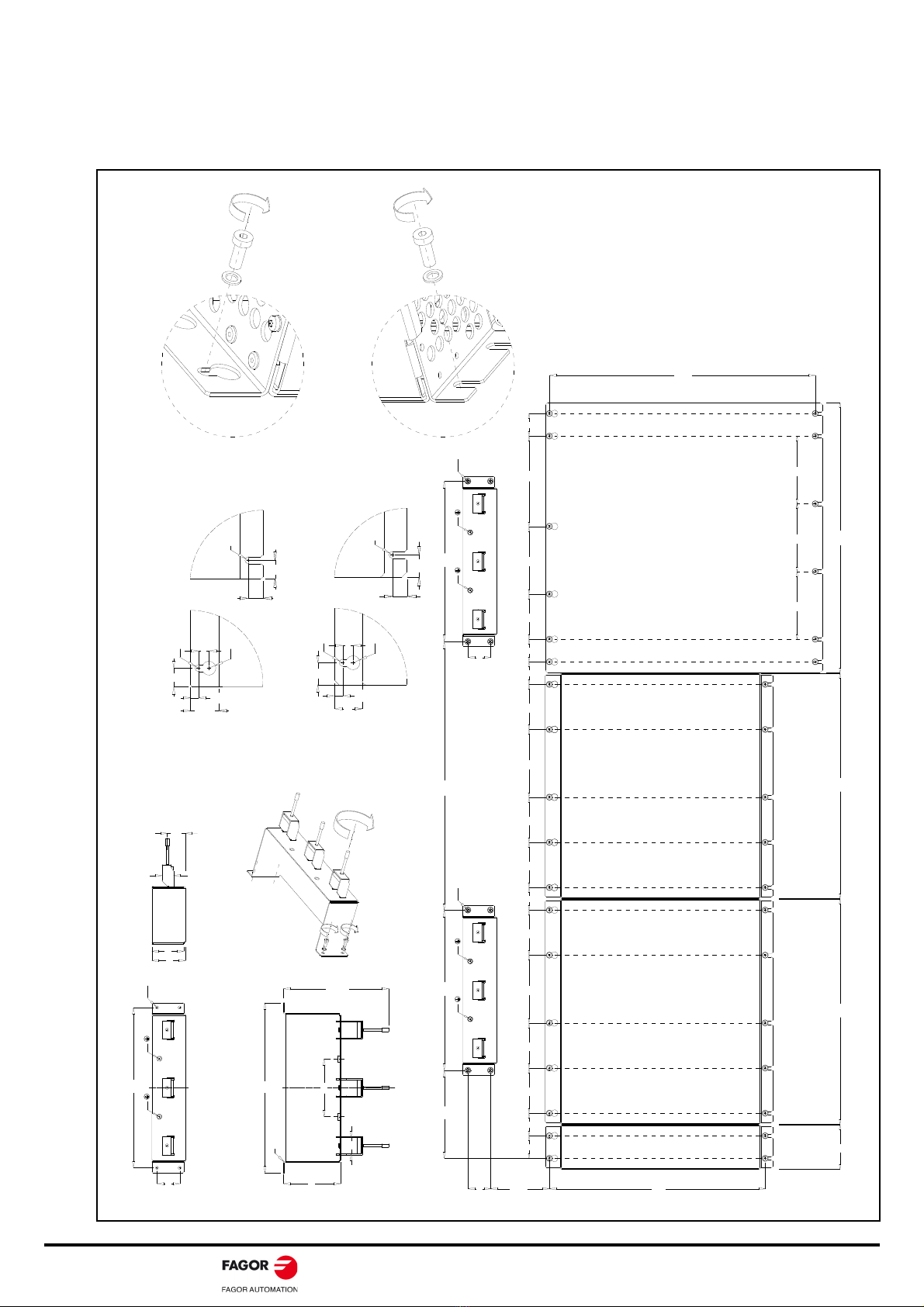
Use the copper plates that are provided as
accessories in the assembly.
Make the connections with wide contact surfaces for
the metal parts.
Remove the paint from contact surfaces.
Try to increase conductivity on two-dimensional
contacts.
Install a protection circuit if there is a risk of
overvoltage.
Route the electrical energy supply lines from the lines
carrying the information.
Note. The electrical field which could induce voltage
spikes on the information lines decreases with
distance.
Route the motor cable at a distance of at least 20 cm
from the signal cable or use shielding plates between
the motor cable and signal cable.
Do not run field bus cables and signal through a single
conduit with DC and AC lines with voltages over 60 V.
The field bus cables, signal lines and analog lines can
be installed in a same conduit.
Recommendation. Separate the conduits where the
cables are running at least 20 cm and make them as
short as possible. Do not install unnecessary cable
loops and use short cables from the central ground
point for connecting to a ground point outside the
electrical cabinet.
Avoid induction loops by choosing common routes for
power, signal and data circuit cables.
Use shielded cables for power supply and motor.
On shielded cables, the unshielded portion of the
cable used to connect them to the connectors must be
as short as possible in order to reduce radiated
emissions.
Use simple shielding for the motor encoder cable. The
system complies with current regulations regarding
immunity with simple shield.
MANDATORY.
Installations of large areas.
Different voltage sources.
Mains through several buildings reducing the current
in the cable shield and the emissions. Connect to
ground the electrical cabinet, the door, the mounting
plate, with ground straps or cables with a cross section
larger than 10 mm² (AWG 6).
MANDATORY.
The ground shields of the digital signal wires must be
connected at both ends to a large surface or through
a conductive housing of the connector. This reduces
disturbances that affect the signal cables and also the
emissions.
The ground shields of the analog signal wires must be
connected directly to the device (signal input),
reducing the ground loops due to low frequency
disturbances.
When a unit does not have a ground connection, the
shield must be connected on the side of the unit
connected to ground.
To connect large cable shield surfaces, use cable and
ground clamps.
Run a single shielded cable, in one piece, without
joints. If a cable must necessary be cut for the
installation, connect it with the shield connections and
through a metal cover at the cut (joint) point. In the
worst case, if it is not possible to use shielded
connectors, keep a minimum length of cable exposed
to disturbances guaranteeing a good connection
between the shields.
Mount switching devices such as contactors, relays
or electro-valves with interference suppression
elements or arc suppressors (e.g. diodes, varistors,
RC circuits).
Install power and control components separately.
Use equipotential cables when having long lines to
reduce the current through the cable shield.
When connecting power cables, the shield of this
cable should be connected to a ground bar.
DANGER.
Neither the user nor the machine manufacturer is
authorized to modificate or repair the drive, not even
to replace boards.
In the event that any safety function suffers a failure,
replace the drive with the same model of the same
version or later and set identical parameters on the
replacement model.
Conduct the partial acceptance test.

QCIG-10/16 QuerCus SERCOS-II Drive System. Installation Guide. Ref.1801/B
7.2 Mechanical installation
Preparing the mounting fixtures
Use the holes and slots prepared for the purpose of
fastening the equipment. Vibrations should be avoided.
Where necessary, use shock-absorbing lanyards. See
figure below.
373
3939 78 78 117 78 78 78 7811739
77 389 389 467
39 39 3915611778
QC-APSS-15
QC-DR-275-SS2
QC-RPS-160-SN0
LIM 160
39
277
M6 R2.75
M6
39
277
M6 R2.75
M6
152
>1
00
464
39
277
99
55
R2.75
58
294
thickness 1.50
M6 M6
max.182
100
20
28
31.5
117 117 117
459.5
R3
12.4
R3
24
7.1
R6
9
19
19
LIM 160
R3
12.4
R3
25.5
7.1
R6
9
19
19
QC-APSS-15 / QC-DR-275-SS2 / QC-RPS-160-SN0
1 N·m
max.
3 N·m
M5
RECOMMENDED
WASHER
DIN 125, M5
M5
3 N·m
RECOMMENDED
WASHER
DIN 125, M5
3 N·m
M5

QuerCus SERCOS-II Drive System. Installation Guide. Ref.1801/B QCIG-11/16
DC BUS connections and power terminal protectors
Coupling
The plates that are provided as accessories and designed for the purpose of making DC power bus connections between the
QC-APSS-15 and QC-DR-275-SS2 equipment and tighten the M5x16 combined screws. See figures 1A/2A.
The plates that are provided as accessories are designed for the purpose of making DC power bus connections between the
QC-DR-275-SS2 and QC-RPS-160-SN0 equipment and tighten the DIN 6923, M10 nuts See figures 1B/2B.
1B 2B
+
-
24 N·m
24 N·m
24 N·m
24 N·m
BUS DC
QC-DR-275-SS2 & QC-RPS-160-SN0
BUS DC
QC-APSS-15 &
QC-DR-275-SS2
2.8 N·m
1A
2A
TERMINAL PROTECTOR
RIVET POSITIONS
bottom view, LIM 160
See 2A
See 1B/2B
RIVET POSITIONS
top view
QC-DR-275-SS2 & QC-RPS-160-SN0
12
3
4
234
1
12
34
top view, LIM 160
1
2 3 4
214
3
ON THE TOP PROTECTORS
ON THE BOTTOM PROTECTOR
TERMINAL PROTECTOR TERMINAL PROTECTOR
TERMINAL PROTECTOR

QCIG-12/16 QuerCus SERCOS-II Drive System. Installation Guide. Ref.1801/B
7.3 Electrical installation
Mains connection
The FAGOR QUERCUS system is designed to be
connected to a three-phase mains between 400 V AC (1-
10 %) and 480 V AC (1+10 %) and a mains frequency of
50/60 Hz.
Certain mandatory protection devices must be added to
the lines that extend from mains to the FAGOR
QUERCUS system. Others are optional.
Isolating transformer or auto-transformer
When the mains voltage must be isolated or adapted to
the levels required by the QUERCUS system, it may be
connected through an isolating transformer or an auto-
transformer. This element will also help reduce the
amount of harmonics on the line although it will not
guarantee the compliance with the CE regulation.
The connection may vary depending on the type of mains
and Electromagnetic Compatibility required by the
machine.
If the type of mains does not require isolating transformers
and they only require a voltage adaptation; we recomment
to install auto-transformers instead of isolating
transformation.
After the transformer, so as to modify the mains to the
range of 400/480 V AC, the following are placed in the
following order: the main switch - S1, the protection fuses,
the differential breaker - Q1, the power contactor - KM1
and the electromagnetic interference line interface
module LIM 160.
Protection fuses
To protect the FAGOR QUERCUS system, fuses must be
included on the lines coming from mains.
Lines leading to the QC-APSS-15 auxiliary power supply
integrated via the A20 connector do not require external
fuses, as they are integrated internally.
Recommended fuses
The fuse references given of the previous table are the
ones that may be installed to obtain the maximum power
on each model. In those cases where the power supply is
oversized, the fuse value should be adjusted to the actual
requirements of the machine.
Differential breaker
On a QUERCUS system, fault DC current, practically flat,
may come up besides the AC currents and pulsating DC
currents. This requires the use of a differential breaker.
Electrical connections
Single-pole power cables
The range of single-pole shielded MPC-1xS power cables
supplied on request by FAGOR to make the power
connections is shown in the attached table. These are
supplied without any terminals. The number of cable
meters is available on request. Lengths of 5, 10, 15, 20,
25, 30, 35, 40, 45 and 50 meters are available for 95, 120
and 150 mm² sections.
Flexibility. The minimum bending radius under dynamic
conditions is 7.5xDmax and for static conditions
3.0xDmax.
MANDATORY.
Install the LIM 160 line interface module in the position
indicated in the diagrams shown below.
MANDATORY.
When installing an isolating transformer, the secondary
must a have a star (Y) configuration with access to the
mid point which must be connected to grond.
INFORMATION.
Note that FAGOR does not supply the fuses; in other
words, the FAGOR QUERCUS system does not include
the fuses as accessories.
MANDATORY.
DO NOT install external protection fuses in lines that feed
the auxiliary power supply, QC-APSS-15.
i
MANUFACTURER
Rated
current
Rated voltage
IEC 60269 / UL 248
SIBA
20 610 32.315 315 A 690 / 700 V AC
20 610 32. 350 350 A 690 / 700 V AC
20 189 20 315 315 A 690 / 700 V AC
20 566 20.350 350 A 690 / 700 V AC
MANDATORY.
Install a universal type B breaker (valid for AC, pulsating
DC and flattened DC currents) and selective switch-off
(delayed switch-off).
WARNING.
It is not recommended to use differential breakers
sensitive to pulsating currents and, overall, general
purpose differential breakers. In this cases, undesired
stops might occur due to the high sensitivity of those
devices to pulsating currents. Therefore, never use AC
type differential breakers.
INFORMATION.
In order for FAGOR'S QUERCUS system to meet the
European Directive on Electromagnetic Compatibility
2014/30/EU, the rules on equipment installation must be
strictly followed regarding:
Mounting the LIM 160 ·MAINS FILTER+CHOKE·
Electrical installation of the power stage: wiring to
mains and motor-drive power connection/drive.
Spindle
motor
I S1
(A)
Reference S
(mm²)
Dmax
(mm)
FM9-A100 189.9 MPC-1x
95
-
M 95 22.0
FM9-B113 214.6 MPC-1x
120
-
M 120 23.6
FM9-A130 246.9 MPC-1x
150
-
M 150 25.8
i

QuerCus SERCOS-II Drive System. Installation Guide. Ref.1801/B QCIG-13/16
Power and ground connections
shield shield
shield
shield shield
shield
MPC-1xS
3x 400/480 V AC
50/60 Hz
Connect each shield of the
MPC-1xS single-pole cable
shield to the ground cable
inside the terminal box
Connect the ground cable to the ground
screw inside the terminal box and to the
grounding plate in the electrical cabinet
L1 L2 L3 PE
S/2
MPC-1xS
MPC-1xS
FM9
SPINDLE
MOTOR
QC-APSS-15
QC-DR-275-SS2
QC-RPS-160-SN0
LIM 160
It is not necessary to remove the lid
for the +24 V DC connection.
Run the two wires along the upper
channal
FAGOR does not
provide the terminals
FAGOR does not
provide the terminals
grounding
plate
grounding
plate
3x 400/480 V AC
50/60 Hz
A20
grounding
plate
10 mm
2
mm
2
1
MPC-1xS
MPC-1xS
MPC-1xS
MPC-1xS
MPC-1xS
MPC-1xS
grounding
plate
grounding
plate
t
S/2
t
S/2
t
S/2
t
S/2
t

QCIG-14/16 QuerCus SERCOS-II Drive System. Installation Guide. Ref.1801/B
Schemas
3 x 4 0 0 / 4 8 0 V A C
5 0 / 6 0 H z
I N T E R N A L
B U S
Q C - R P S - 1 6 0 - S N 0
L I M 1 6 0
L I N E
I N T E R F A C E
M O D U L E
P h o n i x ,
5 . 0 0 m m
P h o n i x ,
7 . 6 2 m m
Q C - D R - 2 7 5 - S S 2
Q C - A P S S - 1 5
P E L 1 L 2 L 3
M P C - 1 x
S
m m 2
M P C - 1 x
S
m m 2
M P C - 1 x
S
m m 2
X 6 0
L 1 L 2 L 3
I N P U T
L 1 ' L 2 ' L 3 '
O U T P U T
+ 1 6 5 ° C
A 5 9
1
7
+ 2 4 V D C
+ 2 4 V D C
0 V D C
0 V D C
F A N O F F
1
2
3
4
5
6
7
L 1 L 2 L 3
S - S P I N D L E D R I V E
A U X I L I A R Y P O W E R S U P P L Y
X 1
M A I N P O W E R
S U P P L Y
R E G E N E R A T I V E
I N T E R N A L
B U S
L +
L -
A 1 7
A 1 8
A 1 8
A 1 8
P h o n i x ,
7 . 6 2 m m
A 2 0
3 x 4 0 0 / 4 8 0 V A C
5 0 / 6 0 H z
L 1
L 2
L 3
N
3 x 1 . 0 m m 2
P h o n i x ,
3 . 5 0 m m X 3 3
D a +
D b -
1
2
- K
L 1
L 2
L 3
P E
UVW
M P C - 1 x
S
m m 2
s c t i o n ³
S / 2
m m 2
G P
s p i n d l
m o t o r
X 6
X 1
O U T
I N
N O D E
X 6
++-
-
1
M P C - 1 x
S
m m 2
M P C - 1 x
S
m m 2
N
I N 7 ·
P L C ·
+ 2 4 V D C
P T C
CNC
I N
O U T
O U T
I N
N O D E
2
S E R C O S - I I
S T O 1
S T O G N D 1
S T O 2
S T O G N D 2
1
2
3
4
5
6
S T O F B a
S T O F B b
1 6
X 1 3
1 6
X 3 4
n o t a p p l i c a b l
U V W
s c t i o n ³
S / 2
m m 2
G P
M P C - 1 x
S
m m 2
M P C - 1 x
S
m m 2
M P C - 1 x
S
m m 2
s c t i o n
³
S / 2
m m 2
G P
3 x 1 m m 2
UV W
X 6 0
UVW
P h o n i x ,
7 . 6 2 m m E R R O R R E S E T
S P E E D E N A B L E
R P S E N A B L E
G N D
1
2
3
4
5
6
S Y S T E M O K
1
6
X 3 5
S Y S T E M O K
G P . Gr o u n d i n g Pl a t
P h o n i x ,
3 . 5 0 m m
X 1 2 B -
B +
-
+
1
2
3
4
1
4
c o n t r o l o f t h
x t r n a l - K M 1 c o n t a c t o r
x t r n a l p o w r s u p p l y
+ 2 4 V D C
P h o n i x ,
2 . 5 0 m m
s o f t - s t a r t
a c t i v a t i o n
Sa f Br a k Co n t r o l
S. Sc t i o n i n m m
2
System connection diagram
I n t r n a l B u s
W i r - R i b b o n
C a b l
P O W E R D C B U S
w i t h Q C - R P S - 1 6 0 - S N 0
I N
O U T
X 1
X 1
R S - 2 3 2
S r i a l l i n
i n t r f a c
b o a r d
( S u b - D , F 9 )
X 5
( S u b - D , M 9 )
I N
O U T
( S u b - D , M 9 )
M
3
U 1
U
D i g i a l s p i n d l e m o d u l a r d r i v e
Q C - D R - 2 7 5 - S S 2
N O D E
P C - C o m p u e r
S p i n d l e m o o r
F M 9 - x 1 x x - C 5 C x - E 0 1
2
3R x D
T x D
( S u b - D , F 9 )
X 5
2
3
R x D
T x D
V
W
V 1
W 1
1 0
2
1
9
1
1 0
G P
s c t i o n
³
S / 2 m m 2
G P
s c t i o n
³
S / 2 m m 2
( S u b - D , F 1 5 )
161 1
51 0 1 5
2
3
4
1 2
1 3
1 4
7
8
9
O v r a l l s h i l d . T w i s t d p a i r s .
T h o v r a l l s h i l d m u s t b c o n n c t d
t o t h m t a l h o u s i n g o f t h c o n n c t o r s
a t t h F M 9 n d a n d Q C - D R - 2 7 5 - S S 2 n d
R E F C O S
S I N
R E F S I N
R S 4 8 5 +
R S 4 8 5 -
G N D
+ 8 V D C
C O S
6
5
4
3
2
1
1 1
1 4
S i g n a l P i n
T E M P -
T E M P +
1 3
1 5
1 0
2
6
5
1
8
3
4
1 2
7
P i n
9
3 x M P C - 1 x S m m 2
C a b l w i t h o u t t r m i n a l s
E O C - 1 2
m o t o r f r o n t v i w
E 2 1 D
( S u b - D , F 1 5 )
161 1
51 0 1 5
2
3
4
1 2
1 3
1 4
7
8
9
G P . Grounding Pl a t
D i r e c f e e d b a c k
R a d y m a d c a b l
Q C - E E C - 0 3 / 0 5 / 1 0 / 1 5 / 2 0 / 3 0 / 5 0
l n g t h i n m t r s ; c o n n c t o r s i n c l u d d
C a b l e 2 x 4 x 0 . 2 5 + 1 x 2 x 0 . 5
E 2 1
A - / R E F C O S
B + / S I N
B - / R E F S I N
I 0 + / D A T A + / R S 4 8 5 +
A + / C O S
6
5
4
3
2
1
S i g n a l P i n
I 0 - / D A T A - / R S 4 8 5 -
C L K -
C L K +
8
7
+ 5 V D C
+ 5 V D C
1 0
9
G N D
G N D
1 2
1 1
+ 8 V D C
T E M P -
1 4
1 3
T E M P + 1 5
( S u b - D , M 1 5 )
1
X 6
A 1 8
+ 2 4 V D C
G N D
L +
L -
++
-
-
A 1 7
P O W E R D C B U S
w i t h Q C - A P S S - 1 5
5
1
2
3
49
6
7
8
S E R C O S - I I
g r o u n d s c r w o f t h t r m i n a l
b o x o f t h f a n m o t o r
W
V
U
W 1
V 1
U 1
L 1
4 x 1 . 5 m m 2
E L E C T R I C
F A N
m a i n s
3 - p h 4 0 0 / 4 8 0 V A C
5 0 / 6 0 H z
L 2
L 3
Spindle motor connection diagram

QuerCus SERCOS-II Drive System. Installation Guide. Ref.1801/B QCIG-15/16
General diagram of power line connection
Electrical maneuver diagram
Consult full diagrams under chapter 10. Connection
diagrams in the man_qc_pds_hard.pdf manual.
L1 L2 L3
L1' L2' L3'
L2
WVU
TO THE A20
CONNECTOR
QC-APSS-15
TO THE POWER TERMINALS
L1
L2
L3
L1
L3
LIM 160
PE
- S1
MECHANICAL
MAIN SWITCH
- F1
- F2
- F3
L1
L2
L3
N
- Q1
DIFFERENTIAL
BREAKER
POWER MAINS
IT A MUST TO USE FUSES
K1
EARLY OPEN
CONTACT K2
CONTACTOR
-
KM1
EARLY OPEN
CONTACT
K1
EARLY
OPEN
CONTACT
K2
GND
- S1
MECHANICAL
MAIN SWITCH
- KM1
GND
- Q1
DIFFERENTIAL
BREAKER
EARLY
OPEN
CONTACT
KA3,2 KA3,1
+24VDC
AT X35.3
RPS ENABLE
+24VDC
OFF DELAY
TIMER
-KA3
OFF DELAY
CONTACT
OFF DELAY
CONTACT
3x 400-480 VAC
FUSES F1, F2, F3: 690 V AC / 315 A min.
SIBA 20 610 32.315
SIBA 20 610 32.350
SIBA 20 189 20.315
SIBA 20 566 20.350
3x 400-480 VAC
QC-RPS-160-SN0
INPUT
OUTPUT
3x 400-480 VAC
EXAMPLES:
K1. AUXILIARY EARLY OPEN CONTACT
- AUXILIARY CONTACT GAX11 10AE OF THE GA SERIES
OF SWITCHES AND BREAKERS, LOVATO ELECTRIC.
EXAMPLES:
- AUXILIARY CONTACT HI11-P1/P3E 061813OF
APPLICABLE TO SWITCHES AND BREAKERS
P1-.../E,.../EA...,/EZ Y P3-.../E, .../EA, FROM MOELLER.
K2. AUXILIARY EARLY OPEN CONTACT
- AUXILIARY CONTACT HIV IN AUTOMATIC SWITCHES
NZM1, 2 OR 3 FROM MOELLER.
EXAMPLES:
50/60 Hz
PE
N

QCIG-16/16 QuerCus SERCOS-II Drive System. Installation Guide. Ref.1801/B
Code 14460253
Fagor Automation S. Coop.
Bº San Andrés, 19 - Apdo. 144
E-20500 Arrasate-Mondragón, Spain
Tel: +34 943 719 200
+34 943 039 800
Fax: +34 943 791 712
E-mail: [email protected]
www.fagorautomation.com
FMD-4-137-0
Ref:1801/A
Table of contents
Other Fagor Control Unit manuals