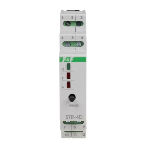
Programming time of enclose
1. Press and hold a button PROG for time when green LED U start to
pulsate.
2. When we again press a button PROG (START). Controller start
count a time which is to signal by pulsate of green LED.
3. Press again a button PROG (STOP). Controller remember a
counted time. Programmin mode is automaticly closed ( green LED U
shine continually).
* If at time 30 sec from start programming mode a count of
time doesn’t to start, then controller will out from
programming mode.
* Max time for programming 10min. Test by long time than
10 min to cause controller automaticly out from
programming mode.
* Input to programming mode posible is only when motor
of roller is OFF.
* In programming mode a controller doesn’t to react for
outward control signal .
Do not install to device which is broken or incomplete.
During assembly of controller should be take special care
Wrong connection could cause to give a shock and/or
break controller or connected device
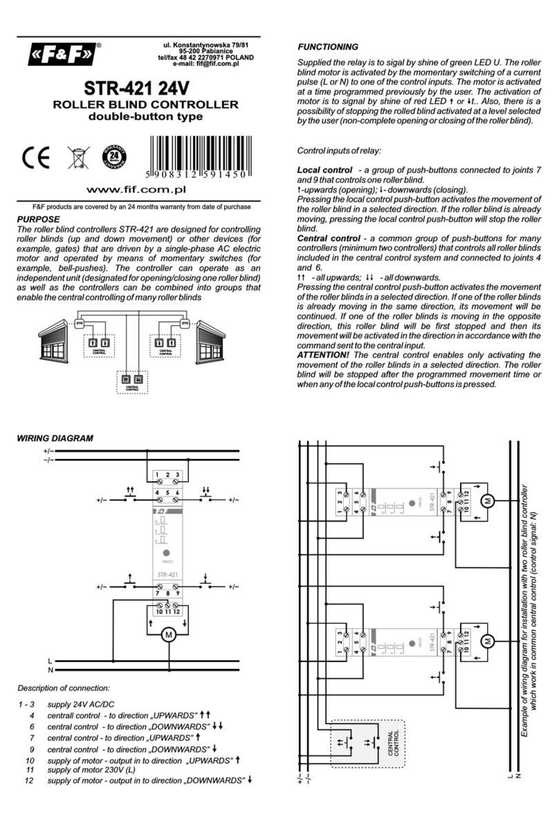
5. Controlled roller motor connect properly to joints 3 and 4 and to N.
6. Take ON the power.
7. Programming to time of upwards/downwards of roller. Prescribed is
that programmed time should be longer than 10 sec from real time of
upwards/downwards.
4. Choose control option (control impulse L or N). Switch of local
control and central control connect with marks with function to joint to
choosen cable (accordance with choosen control option - L or N).
3. Connect power cable to joint 1-2 with marks.
Group of controllers which working with common central
control should be supplied from the same phase e.g only
L1.
All control inputs of controllers which works separately or
in group should have to common control impulse option -
all are controlling from the same phase, e.g. only L1; or all
from N.
Connection different phase e.g.
and "zero" N to inputs of control inputs of controller can
cause to wrong work of system and break controllers.
L1 and L2; or phase L
Choosing control option from phase (L) to control inputs
should be connect to the same phase as for supply e.g.
only phase L1.
ASSEMBLY
1. Take OFF the power.
2. Put on the controller on the wall or a roller box.
C120523/120524
supply 230V AC
contact relay 8A 250 VAC
current load AC-3 <1,5A
power of connected one phase motor 320W
control pulse current for L/N <1mA
power supply indicator LED green
power consumption 1W
working temperature -25÷50°C
connection signal 4×DY 1mm², l=10cm
supply 4×DY 1,5mm², l=10cm
dimensions Ø55, h=20mm
fixing under plaster box Ø60
TECHNICAL DATA Warranty
The controller uses the strength of the contact relay 8A to
resistive load. Due to the inductive nature of the charge
introduced by the engine shutters should not be charged
more than the contact current 1,5A. Corresponds to
power of motor about 320W.
1. The system is covered by 24 month warranty from date of purchase.
2. The warranty is valid only with proof of purchase.
3. The guarantee is valid ONLY if the assembly has been setup by
certified F & F installer.
4. Notification complaint must be made at point of purchase or directly
4. During the warranty the manufacturer will repair or replace the
module with a new one within 14 days from the date of delivery to the
service.
5. The buyer has the right to replace system components for a new or a
cash refund if found to be removable factory defect.
6. The warranty does not cover:
- mechanical damage and chemical
- damage resulting from improper or inappropriate use of the manual
- damage caused after the sale as a result of accidents or other events
for which they are not liable neither the manufacturer nor the point of
sale, e.g. transport damage, etc.
7. The warranty does not cover acts which, under the instruction
should execute the installer, for example, installing modules, electrical
installation, the installation of other required electrical protection,
inspection, etc.


