FasTest FI Series User manual

FasTest Inc. 1646 Terrace Drive Roseville, MN 55113 Phone: 651-645-6266 Toll Free: 800-444-2373 www.fastestinc.com
Operating Instructions
Note: A tapered washer with a counterbore is used on all FI01, FI1,
FI2, FI3 and FI4 connectors. The retaining ring will be recessed in
the washer’s counterbore when the connector is pressurized
Operating Instructions for FI and FIxM (Metric Termination)
Internal Pneumatic Operated Connector.
FI connectors provide fast, leak-free connections for pressure and vacuum
testing, uid lling and ushing. The connectors are activated by
compressed regulated air acting on a piston which expands an
elastomeric seal to form a leak-tight connection. Testing, lling or ushing
of the piece is accomplished by introducing liquid or gas media through
the FasTest FI connector.
The use of pressurized media for sealing, testing and lling requires a
thorough understanding of the FasTest FI Installation and Operating
Instructions.
Do not operate FasTest connectors without completely reading and
understanding the following Installation and Operating Instructions.
Read and understand each of the following six steps
before operating the connector.
A. Installation of seals.
B. Extended shaft, stroke limit
C. Tapered front washer feature
D. Mounting the connector.
E. Attachment of pilot pressure and test media supply
lines.
F. Connector operation instructions.
A: Installation of Seals
1. For seal replacement, remove retaining ring from shaft tip and slide off
old seal set and washers. Spacer piece is to remain on connector shaft.
2. Seal Set contains elastomer seals, washers and retaining ring. For
complete listing of seal set size ranges see Chart 2.
3. Verify that seals and washers are the same size (outside diameter).
4. Assemble seal set onto shaft per Diagram 1.
5. Attach new retaining ring to groove in shaft tip. Flat side of retaining ring
must face away from washer.
6. A tapered washer with a counterbore is used at the shaft end on
all FI01, FI1, FI2, FI3 and FI4 connectors. The retaining ring will be
contained within the counterbore when pilot pressure is delivered to the
connector
CAUTION:
1) Periodically inspect connector, seals and washers for wear or
damage. Replace worn or damaged connector seal sets to prevent
loss of sealability and personal injury.
2) If replacing seals only, inspect washers for warping, corrosion, or
excessive wear.
3) Replace complete FasTest main seal set if washers are
warped, corroded or worn.
4) Always replace retaining ring when changing the main seal.
B: Extended Shafts:
Connectors with extended shafts are
designed for sealing remote ports or for
applications requiring connectors to be
offset rather than side-by-side mounted
which may be required when multiple test
ports have close center-to-center distances.
Stroke Limiters:
FI connectors that have shaft extensions of at least one inch (1”) beyond
the standard for any model FI connector will be assembled with a stroke
limiter. This feature will prevent over pressurization and excessive travel
of the FI seals when pilot pressure is applied to an FI not placed in a test
piece.
Additionally, if an FI stroke limiter prevents sufcient pressurization for
a sealing or testing application, it may be removed very easily without
reducing the effectiveness of the connector.
C: Dimensions
Retaining Ring
Flat Washer
Seal(s) Flat Washer
Stroke Limiter
Standard on 1” or longer extended FI shafts
Spacer, Extended
Spacer,
Nominal
Housing
Piston
Spacer
Retaining Ring
Tapered Washer
Flat Washer
Seal(s)
Diagram 1:
FI1 with Seal Set
Diagram 2:
FI5 1” extended shaft and standard seal set
Maximum Test Pressure: 120 psi
Vacuum Rating: 10-8 torr
A
F
K
DE
C
Test
Port
Mounting
Holes
Pilot
Port
Diagram 3: Connector Features
L
WP008 1/2009 rev. C
FasTest Inc. 1646 Terrace Drive Roseville, MN 55113 Phone: 651-645-6266 Toll Free: 800-444-2373 www.fastestinc.com
Operating Instructions
Chart 1: FI Connector Dimensions
FI A C D E F K* L*
FI01, FI01M 1.98 1.25
10-32 UNF,
M5X8
10-32 UNF,
1/8 BSPP 0.80
10-32 UNF,
M5X8 0.53
FI1, FI2, FI1M, FI2M 2.44 1.57
1/8** NPSF,
1/8 BSPP
1/8** NPSF,
1/8 BSPP 1.02
1/4-28 UNF,
M6X1.0 0.59
FI3, FI4, FI3M, FI4M 2.60 2.36
1/8** NPSF,
1/8 BSPP
1/8** NPSF,
1/8 BSPP 1.60
1/4-28 UNF,
M6X1.1 1.08
FI5, FI6, FI5M, FI6M 3.66 3.49
1/2** NPSF,
1/2 BSPP
1/2** NPSF,
1/2 BSPP 2.31
1/4-28 UNF,
M8X1.25 1.61
FI7, FI8, FI7M, FI8M 3.36 4.20
3/4** NPSF,
3/4 BSPP
3/4** NPSF,
3/4 BSPP 3.00
1/4-28 UNF,
M6X1.25 1.63
*L = Minimum insertion length of test piece
** Can be used with BSP or NPT male ttings
Chart 2: FasTest FI Connector Seals
Model FIS Seal
Set
Sealing Range No of Seals Max Flow
FI01,
FIO1M
01
1/8NPT*
.330-.394 1
2
0.060"
FI1,
FI1M
11
1/4NPT*
12
13
.394-.472
.472-.551
.551-.630
1
2
1
1
0.130"
FI2,
FI2M
3/8NPT*
21
1/4NPT*
22
23
.630-.709
.709-.797
.787-.866
2
1
2
1
1
0.17"
FI3, FI3M 31
3/4NPT*
32
33
.866-.945
.945-1.024
1.024-1.102
2
2
2
2
0.21"
FI4, FI4m 41
1NPT
42
43
1.102-1.181
1.181-1.260
1.260-1.339
2
2
2
2
0.28"
FI5, FI5M 51
52
1-1/4NPT
53
1.339-1.457
1.457-1.575
1.575-1.693
3
3
3
3
0.56"
FI6, FI6M 61
1-1/2NPT
62
63
1-693-1.852
1.850-2.008
2.008-2.185
3
3
3
3
0.72"
FI7, FI7M 71
2NPT
72
73
2-1/2NPT
2.185-2.305
2.305-2.445
2.445-2.585
3
3
3
3
3
0.92"
FI8, FI8M 81
82
83
2.585-2.725
2.725-2.865
2.865-3.005
3
3
3
0.92"
* Main Seal is neoprene. NPT seals are urethane. FI NPT seals sets
contain a urethane main seal with additional neoprene face seal.
** FI NPT seal sets include a face seal.
Note: “M” Designates metric customer interface. See Chart 1 for metric
mounting hole thread sizes.
D: Mounting of Connector
FI model connector
The test connector must be secured to the test piece with a mechanical
E: Attaching Pressure Lines
FI(M) model connector
1. Attach pilot pressure line to pilot port “E”, Diagram 3. A pneumatic
related source is required to maximize seal life and assure
optimum seal-ability for the application. The pilot pressure should
be minimized to maintain sealing on the test piece without
excessive compression of seal. Excess pilot pressure may
reduce the life of the seal.
2. Attach test media line to test port “D”, Diagram 3.
3. Provide a means whereby test pressure will not be introduced
until pilot pressure required to seal is reached. The means should
also provide quick exhaust of test pressure in the event pilot
pressure falls below the minimum required to seal.
Pilot Pressure. Regulate pilot pressure to the minimum required pressure
for sealing under test conditions (pressure or vacuum). Use of minimum
required pilot pressure will prolong seal life. Generally, a 60 to 90 psi
pneumatic pilot pressure source is required.
Test Pressure. Maximum rated test pressure for standard FI models is
120 psi. With connector secured and pilot activated, introduce gas or liquid
through the FasTest FI connector until desired testing, lling or ushing is
complete.
FasTest, Inc. Product Warranty
FasTest, Inc. warrants its products against defects of workmanship and/or material for 1 year from
the date of the sale by FasTest, Inc. This warranty is void if the product is misused, tampered
with or used in a manner that is not in accordance with FasTest, Inc. recommendations and/or
instructions. FasTest, Inc. is not liable for consequential or other damages including, but not limited
to, loss, dam-age, personal injury, or any other expense directly or indirectly arising from the use of
or inability to use its products either separately or in combination with other products. ALL OTHER
WARRANTIES EXPRESSED OR IMPLIED, WHETHER ORAL OR WRITTEN, INCLUDING BUT
NOT LIMITED TO WARRANTIES OR MERCHANTABILITY OR FITNESS FOR A PARTICULAR
PURPOSE ARE EXPRESSLY EXCLUDED.
Remedy under this warranty is limited to replacement of the product or an account credit in the
amount of the original selling price, at the option on FasTest, Inc. All allegedly defective products
must be returned prepaid transportation to FasTest, Inc. along with information describing the
products performance, unless disposition in the eld is authorized in writing by FasTest, Inc.
or other device to assure the connector is not uncoupled from the test
piece by the uncoupling force of the test itself. The securing or holding
device may be a xture, clamp, cylinder or other appropriate means that
prevents ejection of the test piece from the connector.
Uncoupling force example:
Test piece has a ½” O.D. and is tested at 100 psi maximum. Uncoupling
force = area (π r2) x pressure = π.252 x 100 = 20 lbs. Secured device
should be designed to withstand this force and include an adequate
margin for safety. Do not activate the connector without an adequate and
safe securing mechanism.
Mount the FasTest FI connector to the xture or appropriate device using
either threaded mounting holes on the rear of the connector body, or
appropriate adapter.
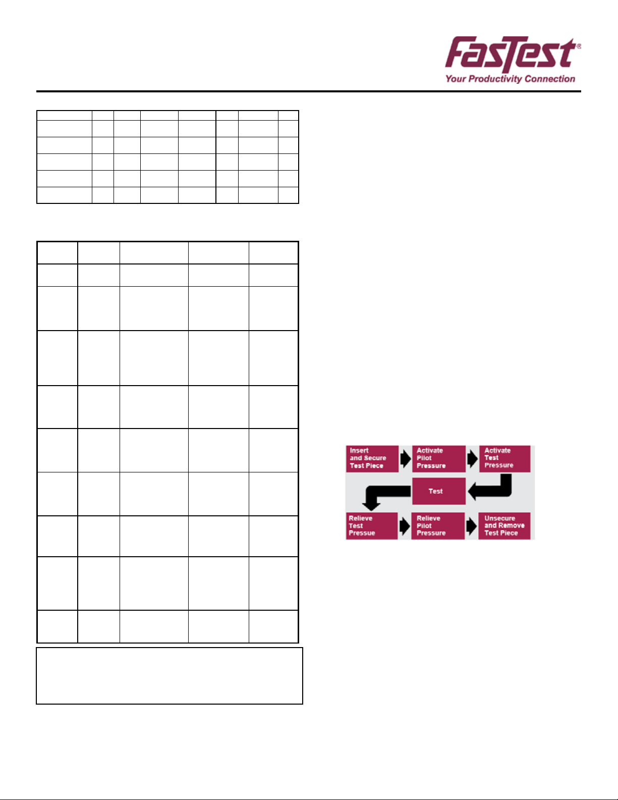
F: Connector Operation
FI Model connector into ports, tubes, etc.
WARNING: The FI connector must be SECURED to the test piece by a
mechanical device before proceeding.
Activate connector testing sequence as shown below
WP008 1/2009 rev. C
Other manuals for FI Series
1
This manual suits for next models
19
Other FasTest Cables And Connectors manuals

FasTest
FasTest 60V Series User manual
FasTest
FasTest ICON 60 User manual

FasTest
FasTest FasCal Series User manual

FasTest
FasTest 60 Series User manual

FasTest
FasTest FasMate Series User manual

FasTest
FasTest FE001 Series Guide

FasTest
FasTest FN Series User manual

FasTest
FasTest SnapMate SCPR50 User manual

FasTest
FasTest FasMate Series User manual

FasTest
FasTest ZN Series User manual


