manuals.online logo
Brands
  1. Home
  2. •
  3. Brands
  4. •
  5. Fasttel
  6. •
  7. Intercom System
  8. •
  9. Fasttel FT20CC User manual

Fasttel FT20CC User manual

FT20CC
Fasttel België, Klipsenstraat 18A, 9160 Lokeren Tel +32 (0)9 2 65 20, [email protected]
FT20CC: Manual ENG1.6
1. Installation Instructions
•Connect the video signal to the terminals V+ and V- (terminals 1 and 4 of the rear connector)
Caution! It is extremely important to maintain the polarity of the video signal
•Connect the power supply provided to the PP terminals (terminals 2 and 3) The polarity is not
important in this case
•When everything is connected correctly, a colour bar will appear in the display, followed by a
series of beeps, after which the display goes into standby mode
2. Configuration Instructions
After removing the extreme right cover, you will find two circular recesses with two push buttons
V+ P P V-
1 2 3
FT20CC: Manual ENG1.6
Each button can have two functions:
Button 2: menu or other selection
Button 1: reset or change function
2.1 Colour, contrast and brightness setting
As a rule, you need not change any settings since the default settings generally work for most
situations
You will first have to set up a connection with your door panel, before you can use the above settings
Briefly press button 2 to make the following appear in overlay mode

BUTTON 2 (menu)
 BUTTON 1 (reset or change)
FT20CC: Manual ENG1.6
You can set 9 levels for colour, 8 for contrast and 10 for brightness
The text “COLOUR” will now flash (not the others)
Pushing BUTTON 1 (change) will increase and automatically adjust the colour temperature The minimum
level can be set by pressing button 1 seven times
By now pressing BUTTON 2 (Next Select), the text “CONTRAST” will now flash (not the others)
The level will change on pressing BUTTON 1
You can adjust the BRIGHTNESS by next pressing BUTTON 2
The menu will disappear after you press BUTTON 2 again
If the settings are correct, you may terminate the connection with the door panel
2.2 Selectivity and cable compensation setting
If the screens are used with one or more Wizard door panels with multiple pushbuttons, the activation
of each screen can be linked to a particular pushbutton
Note: The default setting is such that there will be a response to all buttons of the door panel.
Make sure that the screen is blank, and press BUTTON 2
The following screen will appear
The ‘V13’ next to the text BUTTONS indicates the current software version

BUTTON 2 (other selection)
 BUTTON 1 (change)

BUTTON 2 (other selection)
 BUTTON 1 (change)
FT20CC: Manual ENG1.6
The number 1 will now start flashing This figure will change to red on pressing BUTTON 1 The screen will now
no longer respond to Call Button 1 on the door panel
The figure will turn white and become active again when you press BUTTON 1 once more
You can now make the setting for Call Button 2 by pressing CALL BUTTON 2
You can therefore use BUTTON 2 to navigate through the menu
Sample setting in which only call buttons 1 and 2 are displayed on the screen.
Pressing BUTTON 2 when the number 8 flashes will take you to “CABLE COMP”, with which the video signal
amplitude will be adjusted according to the distance from the door panel
When you press BUTTON 1, the distance will change to 240 400M
Pressing BUTTON 1 again will change it to 400 600M
Pressing Button 1 a third time will change it to 0 240M (= default setting)
You can exit from the menu by now pressing BUTTON 2, after which the screen will go into standby mode
2.3 Reset
To restore the factory settings of the buttons (in other words, maximum 8 buttons), proceed as
follows:

BUTTON 2 (other selection)
 BUTTON 1 (change)
B U T T O N S V13
1 2 3 4 5 6 7 8
C A B L E C O M P
240 400M

BUTTON 2 (other selection)
 BUTTON 1 (change)
FT20CC: Manual ENG1.6
•make sure that the screen is blank
•RESET by pressing BUTTON 1 for 5 seconds, in which case you will hear 2 short beeps
Note: this procedure will not reset the colour and contrast settings.
3. Installation
The FT20CC can be installed in 3 ways:
1 Tabletop mounting: screw in the base provided, below the screen
2 Surface-mounted on the wall: release the black sides of the screen and the 4 crosshead screws in
the screen You can now take off the aluminium backing plate of the screen Drill through the two
pre-drilled holes, and fix the back plate on the wall Be careful not to use oversized screws, as
these could damage the circuit board
3 As built-in model: with optional installation casing FT20CCF
The installation casing is flush-mounted in the wall Keep in mind plaster work that may be done
subsequently Remove the black sides of the screen and the 4 crosshead screws in the screen You
can now take off the aluminium backing plate of the screen Drill through the two pre-drilled
holes and secure the round-head bolts provided, with the round heads on the back Reassemble
the screen and then click it into the installation casing
Reposition the sliding portion of the installation casing if the casing was installed too deep inside
the wall
 BUTTON 2 (not applicable)
 BUTTON 1 (reset)
Other Fasttel Intercom System manuals

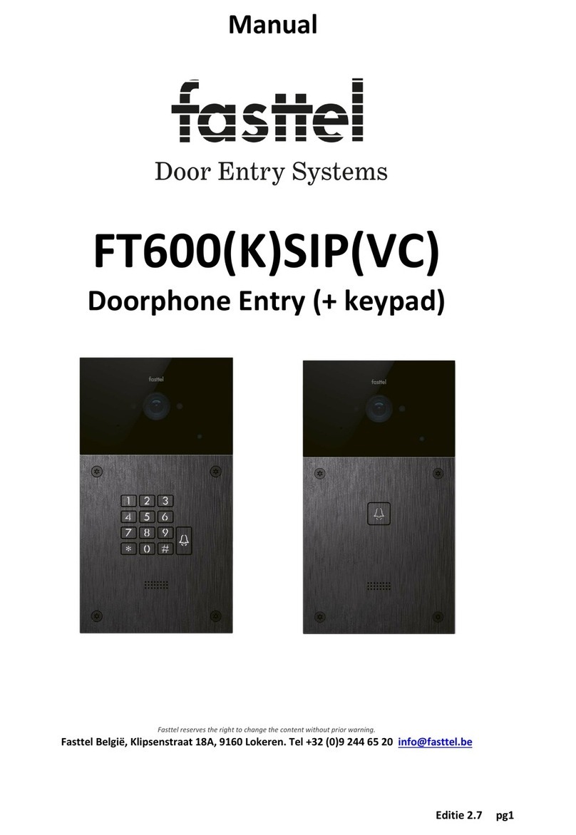
Fasttel Wizard Classic User manual

Fasttel

Fasttel Wizard Classic User manual

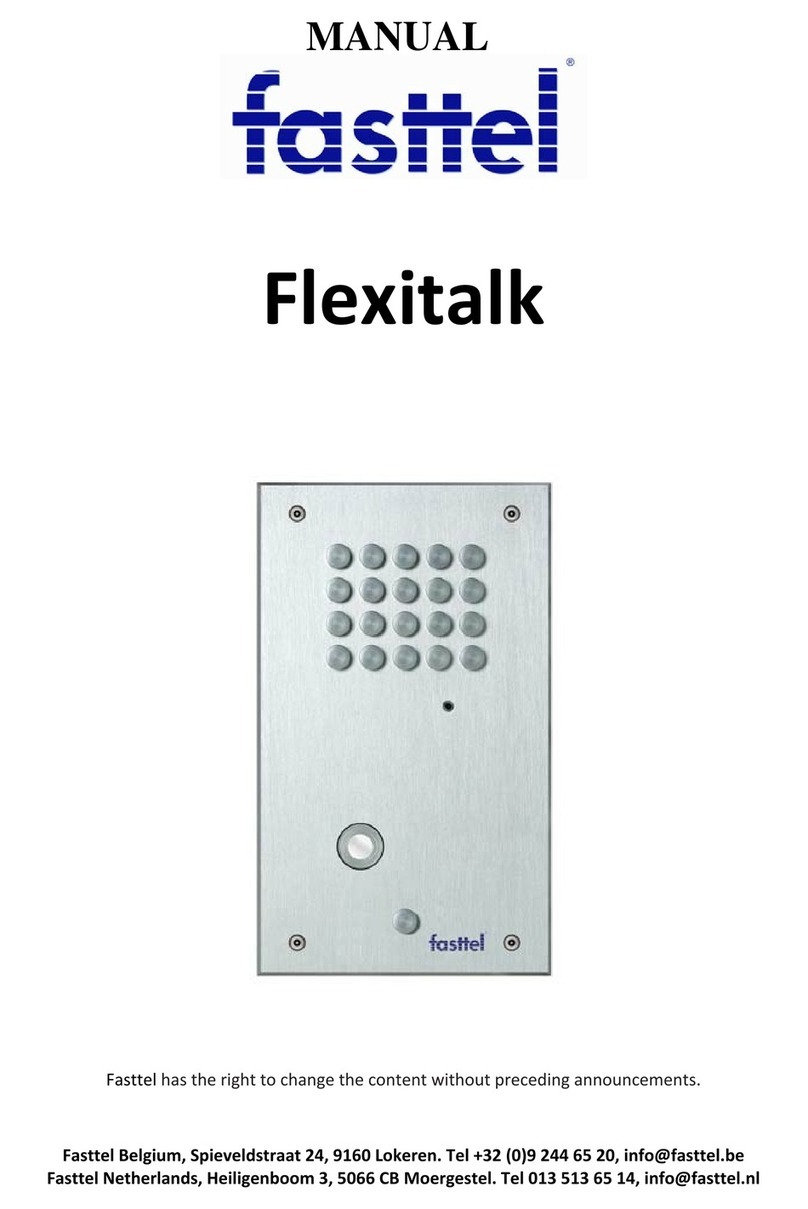
Fasttel FLEXITALK User manual

Fasttel

Fasttel FLEXITALK User manual

Fasttel WIZARD ELITE IP User manual

Fasttel

Fasttel WIZARD ELITE IP User manual

Fasttel Wizard Bronze User manual

Fasttel

Fasttel Wizard Bronze User manual

Fasttel WIZARD CLASSIC IP User manual

Fasttel

Fasttel WIZARD CLASSIC IP User manual

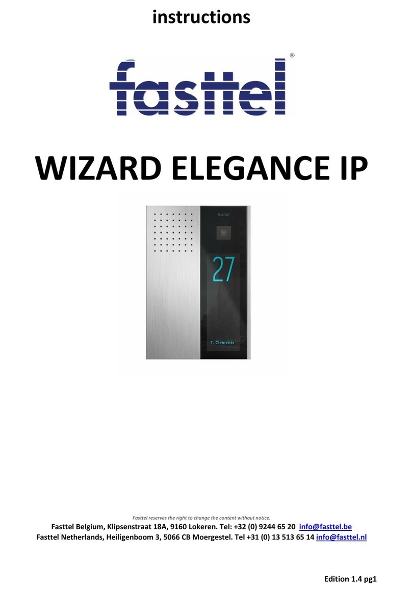
Fasttel WIZARD ELEGANCE IP User manual

Fasttel

Fasttel WIZARD ELEGANCE IP User manual

Fasttel FT600W User manual

Fasttel

Fasttel FT600W User manual

Fasttel FT600VKK User manual

Fasttel

Fasttel FT600VKK User manual

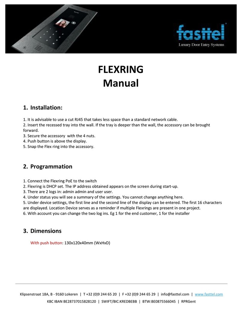
Fasttel FLEXRING User manual

Fasttel

Fasttel FLEXRING User manual

Fasttel FT600(K)SIP(VC) User manual

Fasttel

Fasttel FT600(K)SIP(VC) User manual

Fasttel WIZARD ELITE IP User manual

Fasttel

Fasttel WIZARD ELITE IP User manual

Fasttel FT600KSIP User manual

Fasttel

Fasttel FT600KSIP User manual

Popular Intercom System manuals by other brands

CyberData 011478 Installation quick reference

CyberData

CyberData 011478 Installation quick reference

Esse-ti Diamante user manual

Esse-ti

Esse-ti Diamante user manual

SSS Siedle BVI 750-01 Product information

SSS Siedle

SSS Siedle BVI 750-01 Product information

Aiphone IX System Operation manual

Aiphone

Aiphone IX System Operation manual

tema AA-560 Technical and installation manual

tema

tema AA-560 Technical and installation manual

Toa E-7000TB Specifications

Toa

Toa E-7000TB Specifications

Me PVD-4410 operating instructions

Me

Me PVD-4410 operating instructions

Me ADV-110.1 operating instructions

Me

Me ADV-110.1 operating instructions

Videx VX2300 Installation handbook

Videx

Videx VX2300 Installation handbook

Swann SWHOM-DP875C instruction manual

Swann

Swann SWHOM-DP875C instruction manual

Comelit 6304 user manual

Comelit

Comelit 6304 user manual

urmet domus sentry 1704 installation guide

urmet domus

urmet domus sentry 1704 installation guide

Algo 8036 Installation/configuration

Algo

Algo 8036 Installation/configuration

Extel WEPA 245 BIS User and installation instructions

Extel

Extel WEPA 245 BIS User and installation instructions

Vimar Elvox 875G/S Installer's guide

Vimar

Vimar Elvox 875G/S Installer's guide

HME DX121 EU instructions

HME

HME DX121 EU instructions

Bpt YC/300A Instructions for use and installation

Bpt

Bpt YC/300A Instructions for use and installation

Byron DIC-24112 instruction manual

Byron

Byron DIC-24112 instruction manual

manuals.online logo
manuals.online logoBrands
  • About & Mission
  • Contact us
  • Privacy Policy
  • Terms and Conditions

Copyright 2025 Manuals.Online. All Rights Reserved.