Fbt Audio Contractor Studio Pro 9 B User manual

SPEAKERSYSTEMS

Leinformazionicontenuteinquestomanualesonostatescrupolosamentecontrollate;tuttavianonsiassume
nessunaresponsabilitàpereventualiinesattezze.LaFBTElettronicaS.p.Asiriservaildirittodimodificarele
caratteristichetecnicheedestetichedeiprodottiinqualsiasimomentoesenzapreavviso.
Allinformationincludedinthisoperatingmanualhavebeenscrupulouslycontrolled;howeverFBTisnot
responsibleforeventualmistakes.FBTElettronicaS.p.A.hastherighttoamendproductsandspecifications
withoutnotice.
Lesinformationscontenuesdanscemanuelontétésoigneusementcontrôlées;toutefoisleconstructeurn’est
pasresponsabled’éventuellesinexactitudes.LaFBTElettronicaS.p.A.s’octroieledroitdemodifierlesdonnées
techniquesetl’aspectesthètiquedesesproduitssansavispréalable.
AlleinformationenindieserBedienungsanleitungwurdennachbestemWissenundGewissenzusammengestellt
undüberprüft.Daherkönnensiealszuverlässigangesehenwerden.FüreventuelleFehlerûbernimmtFBTaber
keineHaftung.FBTElettronicaS.p.A.BehältsichdasRechtaufAnderungderprodukteundSpezifikationenvor.
17787#26/09/05
mP

1
AVVERTENZE WARNING
INDICE INDEX
PRECAUZIONI
LAYOUT
PANNELLO CONNESSIONI
ACCESSORI
DIAGRAMMI
CAVI DI COLLEGAMENTO
ESEMPI DI COLLEGAMENTO
SPECIFICHE TECNICHE
BREVI CENNI DI ACUSTICA
1
3
4/5
6
7
8
9
10
11/13
PRECAUTIONS
LAYOUT
CONNECTION PANEL
ACCESSORIES
DIAGRAMS
CONNECTION CABLES
CONNECTION EXAMPLES
TECHNICAL SPECIFICATIONS
BRIEF NOTES ON ACOUSTICS
1
3
4/5
6
7
8
9
10
11/13
PRECAUZIONI PRECAUTIONS
!
|
|
|
<
CAUTION
RISK OF ELECTRIC SHOCK
DO NOT OPEN
TO REDUCE THE RISK OF ELECTRIC SHOCK
DO NOT REMOVE COVER (OR BACK)
NO USER SERVICEABLE PARTS INSIDE
REFER SERVICING TO QUALIFIED SERVICE PERSONNEL
TO REDUCE THE RISK OF FIRE OR ELECTRIC SHOCK
DO NOT EXPOSE THIS EQUIPMENT TO RAIN OR MOISTURE
PER EVITARE IL RISCHIO DI SHOCK ELETTRICO
NON APRIRE IL COPERCHIO
NON USARE UTENSILI MECCANICI ALL'INTERNO
CONTATTARE UN CENTRO DI ASSISTENZA QUALIFICATO
PER EVITARE IL RISCHIO DI INCENDIO O DI SHOCK ELETTRICO
NON ESPORRE L'APPARECCHIATURA ALLA PIOGGIA
O ALL'UMIDITA'
!
ATTENZIONE
RISCHIO DI SHOCK ELETTRICO
NON APRIRE
|
|
|
<
# Evitate di tenere le STUDIO esposte per lungo
tempo all’azione degli agenti atmosferici
(umidità, forti variazioni di temperatura,
eccesso di calore, ecc.);evitate l’accumulo di
polvere e, per quanto possibile, proteggetele
con il loro imballo originale per il trasporto.
# Evitate di toccare il cono degli altoparlanti
con qualsiasi oggetto e con le stesse mani: si
potrebbero arrecare danni irreparabili.
# Evitare di orientare i microfoni nella stessa
direzione degli altoparlanti: potrebbero
generare fastidiosi inneschi (effetto Larsen)
che danneggerebbero gli altoparlanti.
# Per la pulizia non usate solventi tipo acetone
o alcool, che danneggerebbero la finitura
esterna e le serigrafie dei pannelli.
#In caso di cattivo funzionamento di qualsiasi
dispositivo del sistema affidatevi al più vicino
centro di assistenza FBT o ad un centro
specializzato, evitando di provvedere
personalmente.
#Avoid leaving the STUDIO exposed for long
periods to adverse conditions (damp, wide
variations in temperature, excessive heat,
etc...); avoid dust building up and protect them
as far as possible with their original packing
during transport.
# Avoid touching the cones of the loudspeakers
with any object or with your hands, as this could
cause irreparable damage.
# Avoid pointing microphones in the direction
of the speakers, as this could result in annoying
feedback, which can damage speakers.
# When cleaning the STUDIO, don't use
solvents such as acetone or alcohol, which will
damage the units' outer finish and the printing
on the panels.
# In the event of faulty operation of any
component of the system, contact the nearest
FBT service centre or a specialized centre -
never try to solve problems personally.
2
INDEX INHALTSVERZEICHNIS
MESURES DE PRÉCAUTION
PLAN
TABLEAU DE CONNEXIONS
ACCESSOIRES
DIAGRAMME
FILS DE CONNEXION
EXEMPLES DE CONNEXIONS
CARACTERISTIQUES TECHN.
NOTIONS D’ACOUSTIQUE
2
3
4/5
6
7
8
9
10
12/14
VORSICHTSMASSNAHMEN
LAYOUT
ANSCHLUSSTAFEL
ZUBEHÖR
DIAGRAMME
VERBINDUNGSKABEL
ANSCHLUSSBEISPIELE
TECHNISCHE DATEN
KURZE HINWEISE ZUR AKUSTIK
2
3
4/5
6
7
8
9
10
12/14
AVERTISSEMENTS WARNUNG
!
|
|
|
<
VORSICHT
STROMSCHLAGGEFAHR
NICHT ÖFFNEN
STROMSCHLAGGEFAHR NICHT DEN DECKEL ÖFFNEN
WENDEN SIE SICH AN EINEN QUALIFIZIERTEN KUNDENDIENST
UM RISIKEN VON STROMSCHLAG
UND BRAND AUSZUSCHLIESSEN
SETZEN SIE DAS GERÄT KEINEM REGEN ODER FEUCHTIGKEIT AUS
POUR ÉVITER LE RISQUE DE CHOC ÉLECTRIQUE
NE PAS OUVRIR LE COUVERCLE
NE PAS UTILISER D’OUTILS MECANIQUES À L’INTÉRIEUR
CONTACTER UN CENTRE D’ASSISTANCE QUALIFIÉ
POUR ÉVITER LE RISQUE D’INCENDIE OU DE CHOC ÉLECTRIQUE
NE PAS EXPOSER L’APPAREILLAGE À LA PLUIE
OU À L’HUMIDITÉ
!
ATTENTION
RISQUE DE CHOC ÉLECTRIQUE
NE PAS OUVRIR
|
|
|
<
PRECAUTIONS VORSICHTSMAßNAHMEN
# Vermeiden Sie, die STUDIO für längere Zeit
den Witterungseinflüssen auszusetzen
(Feuchtigkeit,starke Temperaturschwankungen,
Übermaß an Hitze usw.); vermeiden Sie ebenso
starke Staubansammlungen und benutzen Sie,
so weit wie möglich, die Originalverpackung für
den Transport.
# Vermeiden Sie, die Kegel der Lautsprecher
derSTUDIO mit irgndeinem Gegenstand oder
mit den Händen zu berühren: es könnten nicht
reparierbare Schäden entstehen.
# Vermeiden Sie die Ausrichtung der
Mikrophone in Richtung der Lautsprecher: die
Mikrophone könnten lästige Schwingungen
erzeugen (Larseneffekt), die die Lautsprecher
beschädigen könnten.
#Zur Reinigung der STUDIO benutzen Sie bitte
keine Lösemittel wie Alkohol oder Azeton, da
diese der Außenschicht und dem Filmdruck auf
den Schalttafeln schaden würden.
# Im Falle eines fehlerhaften Ablaufs einer der
vorhandenen Einrichtungen des Systems,
wenden Sie sich bitte an den nächstliegenden
Kundendienst der FBT oder an ein
Fachgeschäft; vermeiden Sie Eigenreparaturen.
# Evitez de laisser exposer trop longtemps les
STUDIO à l'action des agents atmosphériques
(humidité, fortes variations de température,
excès de chaleur, etc.); évitez l'accumulation de
poussière et pour le transport, protégez-les, si
possible, avec leur emballage d'origine.
# Evitez de toucher les cônes des hauts-
parleurs des STUDIO avec l'un ou l'autre objet
ou avec les mains, car des dommages
irréparables pourraient se produire.
# Evitez d'orienter les microphones dans la
direction des hauts-parleurs, car ils pourraient
provoquer des amorces gênantes (effet Larsen)
qui endommageraient les hauts-parleurs.
# Pour le nettoyage des STUDIO, n'utilisez pas
de solvants du type acétone ou alcool, car ils
pourraient endommager les finitions
extérieures et les sérigraphies des panneaux.
# En cas de mauvais fonctionnement d'un des
dispositifs du système, adressez-vous au
centre d'assistance FBT le plus proche ou à un
centre spécialisé et évitez d'intervenir
personnellement.

3
Adattatore integrato per stativo
Built-in adapter for stand mounting
Adaptateur intégré pour statif
Integrierter adapter für stativ
Inserto filettato per stativo
Threaded insert for stand mounting
Insert fileté pour statif
Gewindeeinsatz für stativ
Maniglia integrata
Built-in handle
Poignée intégrée
Integrierter tragegriff
Pannello connessioni
Connection panel
Tableau de connexion
Anschlusstafel
Griglia metallica di protezione
Protective metal grille
Grillage métallique de protection
Metallschutzgitter
Logo orientabile
FBT logo orientable
Logo orientable
Orientierbares logo
Woofer
Tromba+driver
Horn+driver
Pavillon+driver
Adattatore per supporto a muro orientabile
Adapter for adjustable wall support
Adaptateur pour support à mur orientable
Adapter für orientierbare wandbefestigung
Adattatore per supporto a muro orizzontale
Adapter for horizontal wall support
Adaptateur pour support à mur horizontal
Adapter für waagerechte wandbefestigung
Adattatore per supporto a muro orizzontale
Adapter for horizontal wall support
Adaptateur pour support à mur horizontal
Adapter für waagerechte wandbefestigung
LAYOUT LAYOUT
O
CAUTION
RISK OF ELECTRIC SHOCK
DO NOT OPEN
|
|
|
<
80+20WPROCESSEDACTIVEMONITOR
STUDIO PRO9BA
19681 PRO 9BA
4
UK
I
FD
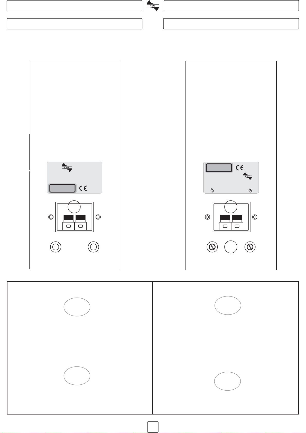
PANNELLO CONNESSIONI CONNECTION PANEL
PANNEAU CONNEXIONS BUCHSENFELD
STUDIO PRO 9 B/WSTUDIO PRO 9 B/W
Collegare alla morsettiera (A) la presa di uscita
dell’amplificatore di potenza o del mixer amplificato;
utilizzare la stessa morsettiera per il collegamento di
più sistemi (vedi esempi di collegamento).
Prima di effettuare i collegamenti regolare la tensione
di ingresso e la potenza di uscita tramire i due
selettori (B)
Connect the output socket of a power amplifier or
amplified mixer to the terminal board (A); use the same
terminals to connect several systems (refer to the
connection examples).
Before making the connections set up the input
voltage and output power by means of the two
selectors (B)
Brancher au bornier (A) la prise de sortie de
l’amplificateur de puissance ou du mixeur amplifié;
utiliser le même bornier pour le branchement de
plusieurs systèmes (voir les exemples d connexions).
Avant d’effectuer les connexions, régler la tension et la
puissance de sortie à l’aide des deux sélecteurs (B)
Bei Modell STUDIO PRO 9B/W an die Klemmensleiste
die Ausgangsbuchse des Leistungsverstärkers oder
des verstärkten Mixers anschließen; dieselbe
Klemmenleiste für den Anschluss mehrerer Systeme
verwenden (siehe Anschlussbeispiele).
Vor Ausführung der Anschlüsse die
Eingangsspannung und Ausgangsleistung über die
beiden Regler (B) einstellen
STUDIO PRO 9 BT/WTSTUDIO PRO 9 BT/WT
++
NOMINAL IMPEDANCE
RECOMMENDED AMPLIFIER (@16 OHM)
SHORT TERM POWER RATING (IEC268-5)
FREQUENCY RANGE (@ -10dB)
SENSITIVITY (@1W, 1m)
MAXIMUM SPL
MADE IN ITALY
8 OHM
120W rms
240W rms
80Hz - 20kHz
95.5dB
116.5 - 119.5dB
STUDIO PRO 9 BSTUDIO PRO 9 B
19678 PRO 9B
++
MADE IN ITALY
STUDIO PRO 9 BTSTUDIO PRO 9 BT
70V
5W/-12dB
20W/-6dB
100V
80W/0dB
45W/-3dB
MAIN OUTPUT
NOMINAL IMP. (const. 100V)
RECOMMENDED AMPLIFIER
FREQ. RANGE (@ -10dB)
SENSITIVITY (@ 1W / 1m)
MAXIMUM SPL (@ 1m)
NOMINAL IMP. (const. 100V)
RECOMMENDED AMPLIFIER
FREQ. RANGE (@ -10dB)
SENSITIVITY (@ 1W /1m)
MAXIMUM SPL (@ 1m)
2000-500-230-125 ohm2000-500-230-125 ohm
80Wrms80 Wrms
80Hz - 20kHz80Hz -20kHz
95.5 dB95.5 dB
115 - 118 dB115 -118 dB
19680 PRO 9BT
A A
B

5
# : Electronically balanced inputs and
outputs connectors. The XLR+Hack Combo “IN” input
connector allows connection of a low
impedance dynamic microphone or a
preamplified signal such as a mixer
output; the XLR “OUT” output connector is
connected in parallel (link) with the “IN”
input connector allowing the connection
of several speakers with the same signal.
# : Volume potentiometer to adjust
the general level of the signal. In normal
circumstances the best performance is
obtained with the volume knob set to
approximately the 3/4 position.
# : Switch to isolate the
chassis ground and the signal ground.
With the pushbutton pressed (on), the
input signal ground is electrically
disconnected from the chassis ground
circuit; in the presence of a hum problem
on the speaker press this pushbutton to
isolate “ground loops” which can often
give rise to this kind of disturbance. With
the pushbutton released the signal ground
is electrically connected to the chassis
ground. USE THE GROUND LIFT OPTION
ONLY FOR BALANCED SIGNALS.
# : Power ON led.
# : Includes the ON/OFF
switch, the socket for connection to mains
power and the power circuit fuse.
IN - link - OUT
VOL
GND LIFT
PWR
POWER SOCKET
# : Prese di ingresso ed uscita bilanciate
elettronicamente. La presa “IN” XRL+Jack-Combo-
consente il collegamento di un microfono
dinamico a bassa impedenza o un segnale
preamplificato come quello in uscita da un
mixer; l’uscita “OUT” XLR è connessa in
parallelo (link) con l’ingresso “IN”
permettendo il collegamento di più
diffusori con lo stesso segnale.
# : Potenziometro di volume che
regola il livello generale del segnale.
Normalmente le migliori prestazioni si
ottengono con la manopola posizionata a
circa 3/4 della sua corsa.
# : Interruttore per la
separazione elettrica tra il circuito di
massa e il circuito di terra. Con il pulsante
premuto (on) la massa dei segnali in
ingresso viene elettricamente scollegata
dal circuito di terra (identificato nello
chassis); nel caso si manifesti un ronzio sul
diffusore questa posizione provvede ad
aprire gli “anelli di massa”, spesso causa di
tali disturbi. Con il pulsante rilasciato la
massa dei segnali in ingresso viene
elettricamente collegata al circuito di terra
dell’apparecchio (identificato nello
chassis). UTILIZZARE IL GROUND LIFT
SOLO PER SEGNALI BILANCIATI.
# : Led che segnala l’accensione del
sistema.
# Comprende
l’interruttore di accensione del sistema, la
presa per il collegamento alla rete elettrica
e l’alloggiamento del fusibile di protezione
del circuito di alimentazione.
IN - link - OUT
VOL
GND LIFT
PWR
PRESA DI ALIMENTAZIONE
PANNELLO CONNESSIONI CONNECTION PANEL
PANNEAU CONNEXIONS BUCHSENFELD
80+20W PROCESSED ACTIVE MONITOR
STUDIO PRO 9BA
# : Elektronisch ausbalancierte Ein- und
Ausgangsbuchsen. Die "IN" XRL+Jack Combo Buchse
gestattet den Anschluss eines dynamischen Mikrophons
mit niedriger Impedanz bzw. eines vorverstärkten Signals,
wie zum Beispiel des Ausgangssignals eines Mischpults;
durch den parallel (link) mit dem "IN" Eingang geschalteten
"OUT" XLR Ausgang lassen sich mehrere Lautsprecher an
das gleiche Signal anschließen.
# : Potentiometer zur Regelung des allgemeinen
Lautstärke-Signalpegels. Normalerweise erhalten Sie die
beste Wiedergabe bei Lautstärkeregler auf ca. 3/4
Position.
# : Schalter zur elektrischen Trennung von
Masse- und Erdkreis. Bei gedrückter Taste (on) wird die
Masse der Eingangssignale elektrisch von dem (im
Chassis gekennzeichneten) Erdkreis getrennt; sollte der
Lautsprecher brummen, öffnen sich in dieser Position die
"Massekreise" die oft die Ursache dieser Störung sind. Bei
ausgerasteter Taste wird die Masse der Eingangssignale
elektrisch mit dem (im Chassis gekennzeichneten)
Erdkreis verbunden. VERWENDEN SIE GROUND LIFT NUR
FÜR AUSBALANCIERTE SIGNALE.
# : LED zur Anzeige der Systemeinschaltung.
#
Schließt den Einschalter des Systems, die
Anschlussbuchse an das Stromnetz, sowie die Aufnahme
für die Schutzsicherung des Stromkreises ein.
IN - link - OUT
VOL
GND LIFT
PWR
VERSORGUNGSANSCHLUSS
# : prises d'entrée et de sortie, équilibrées
électroniquement. La prise “IN” XRL+Jack-Combo-
permet la connexion d'un microphone dynamique à basse
impédance ou d'un signal pré-amplifié comme le signal de
sortie d'une console de mixage; la sortie «OUT» XLR est
branchée en parallèle (link) avec l'entrée «IN» permettant la
connexion de plusieurs haut-parleurs au même signal.
# : potentiomètre du volume réglant le niveau général
du signal. Normalement, les meilleures performances
s'obtiennent lorsque le bouton se trouve à environ 3/4 de sa
course.
# : commutateur de séparation électrique des
circuits de masse et de terre. Lorsque le bouton (on) est
pressé, la masse des signaux d'entrée est déconnectée
électriquement du circuit de terre (indiqué dans le
châssis); dans cette position, en cas de bourdonnement de
l'enceinte, les “anneaux de masse”, qui sont souvent la
cause de ces perturbations, sont ouverts. Lorsque le
bouton est relâché, la masse des signaux d'entrée est
reliée électriquement au circuit de terre de l'appareil
(indiqué dans le châssis). UTILISER "GROUND LIFT"
UNIQUEMENT POUR LES SIGNAUX ÉQUILIBRÉS.
P : témoin LED signalant que le système est sous
tension.
Elle consiste de l'interrupteur marche/arrêt du système, de
la prise secteur et du logement du fusible de protection du
circuit d'alimentation.
IN - link - OUT
VOL
GND LIFT
WR
PRISE D'ALIMENTATION
#
#
O
T 630 mA 250V
45VA
230V 50Hz
CAUTION
RISK OF ELECTRIC SHOCK
DO NOT OPEN
|
|
|
<
MADE IN ITALY
Volume
Out
In
Link
Gnd Lift
Pwr
JACK 1
3
2
X
L
R
XLR
1-Gnd
2-Hot
3-Cold
BUILT IN AMP. :
FREQ. RANGE (@-10dB) :
MAX. SPL (@ 1m) :
SENSITIVITY (@1W, 1m) :
80+20W
70Hz - 20kHz
114dB
95 dB
+12dB line
0dB line
19681 PRO 9BA
STUDIO PRO 9 BASTUDIO PRO 9 BA

6
UK
D
F
I
UK
I
F
D
ACCESSORI ACCESSORIES
ACCESSOIRES ZUBEHÖR
SJ9UB (nero/black)
SJ9UW (grigio/grey RAL 7035)
SJ9B (nero/black)
SJ9W (grigio/grey RAL 7035) ST 20B
Mod. SJ 9U
1. Selezionare con cura l’area dove installare i
diffusori; assicurarsi che la struttura sia adeguata a
sopportare il peso del box; fissare la base della staffa
al muro utilizzando appropriate viti su tutti i fori di
fissaggio della staffa.
2. Posizionare il diffusore tra i due bracci della staffa e
fissarlo tramite i due inserti filettati
1. Take care when selecting the place of speaker
installation; ensure the structure is adequate to
withstand the weight of the box; fix the base of the
bracket to the wall using suitable screws in all bracket
fixing holes.
2. Position the speaker between the two bracket arms
and secure by means of the two threaded inserts
1. Den Installationsort der Lautsprecher sorgfältig
wählen; sicherstellen, dass die Struktur für das
Gewicht der Lautsprecherboxen geeignet ist;
passende Schrauben in alle Bohrungen des Bügels
einsetzen und die Basis des Haltebügels an der Wand
befestigen.
2. Den Lautsprecher zwischen den beiden Armen des
Haltebügels anbringen und mit den beiden
Gewindebuchsen befestigen.
1. Sélectionner attentivement l'endroit où les
enceintes seront installées ; s'assurer que la structure
soit en mesure de supporter le poids du caisson ; fixer
au mur la base de la bride à l'aide de vis adéquates sur
les trous de fixation de la bride.
2. Placer l'enceinte entre les deux bras de la bride et la
fixer entre les deux pièces intercalaires filetées
>Accertarsi che lo stativo supporti il peso
della cassa
>Non superare l’altezza consigliata (160cm)
>Posizionare lo stativo su una superficie non
sdrucciolevole e piana
>Per rendere stabile lo stativo allargare al
massimo i piedini
>Make sure the stand can support the weight of the box
>Do not exceed the recommended height (160cm)
>Position the stand on a flat, non-skid surface
>To make the stand more stable open the feet as wide as
possible
>Assurez-vous que le statif supporte le poids de l’enceinte
>Evitez de dépasser la hauteur conseillée (160cm)
>Positionnez le statif sur une surface non glissante et plate
>Pour assurer la stabilité du statif écartez les pieds aux
maximum
>Stellen Sie sicher, dass das Stativ dem Gewight der Box
angemessen ist
>Die empfohlene Höhe nicht überschreiten (160cm)
>Das Stativ auf einer rutschfesten und ebenen Oberfläche
aufstellen
>Sorgen Sie dafür, dass die Füße des Stativs so weit wie
möglich auseinander gestellt sind, um optimale Stabilität zu
gewährleisten

7
DIAGRAMMI DIAGRAMS
DIAGRAMME

8
CAVI DI COLLEGAMENTO CONNECTION CABLES
FILS DE CONNEXION VERBINDUNGSKABEL
CAVI DI COLLEGAMENTO CONNECTION CABLES
12 21
33
Lato saldatureLato contatti
1. Massa 2. Fase + 3. Fase -Schermo (Shield) Caldo (Hot) Freddo (Cold)
XLR
*SPEAKON è un marchio registrato NEUTRIK *SPEAKON is a registred trademark of NEUTRIK
1+ Positivo/Positive
1- Negativo/Negative
Speakon*
1+
2+
2- 1-
XLR-F (micro)
1= SHIELD
2= HOT
3= COLD
LINE
X
L
R
JACK
12
3
NEUTRIK XLR/JACK - COMBO
Jack stereo / bilanciato/balanced
TIP=Positive (+ or hot)
SLEEVE=Shield or ground
RING=Negative (- or cold)
TIP
TIP
RING RING
SLEEVE SLEEVE
Côté soudures
Geschlossene seite
Côté contacts
Kontaktseite
*SPEAKON est une marque déposée NEUTRIK *SPEAKON ist ein eingetragenes Warenzeichen von NEUTRIK
TIP
RING
SLEEVE
TIP
RING
SLEEVE
1
2
3
1
2
3
XLR-F XLR-M
XLR-M
TIP
RING
SLEEVE
1
2
3
BILANCIATI / BALANCED/SYMÉTRIQUES/AUSBALANCIERT
SBILANCIATI / UNBALANCED/ASYMÉTRIQUES/NICHT AUSBALANCIERT
XLR-M
TIP
SLEEVE
1
2
3
XLR-M
TIP
SLEEVE
1
2
3
XLR-F
1
3
CENTRE
SCREEN
2
TIP
SLEEVE
TIP
SLEEVE
TIP
RING
SLEEVE
TIP
RING
SLEEVE
TIP
SLEEVE
TIP
SLEEVE
1
2
3
CENTRE
SCREEN
XLR-F XLR-M
1
2
3
1
2
3
INSERT CORD
TIP
RING
SLEEVE
TIP (send)
SLEEVE
TIP (return)
SLEEVE
XLR-M
XLR-F
TIP
RING
SLEEVE
1
2 (send)
3
1
2 (return)
3
TIP
RING
SLEEVE
CENTRE (send)
SCREEN
CENTRE (return)
SCREEN
FILS DE CONNEXION VERBINDUNGSKABEL
2+
2-
SPEAKER INPUT[
[
LINK
9
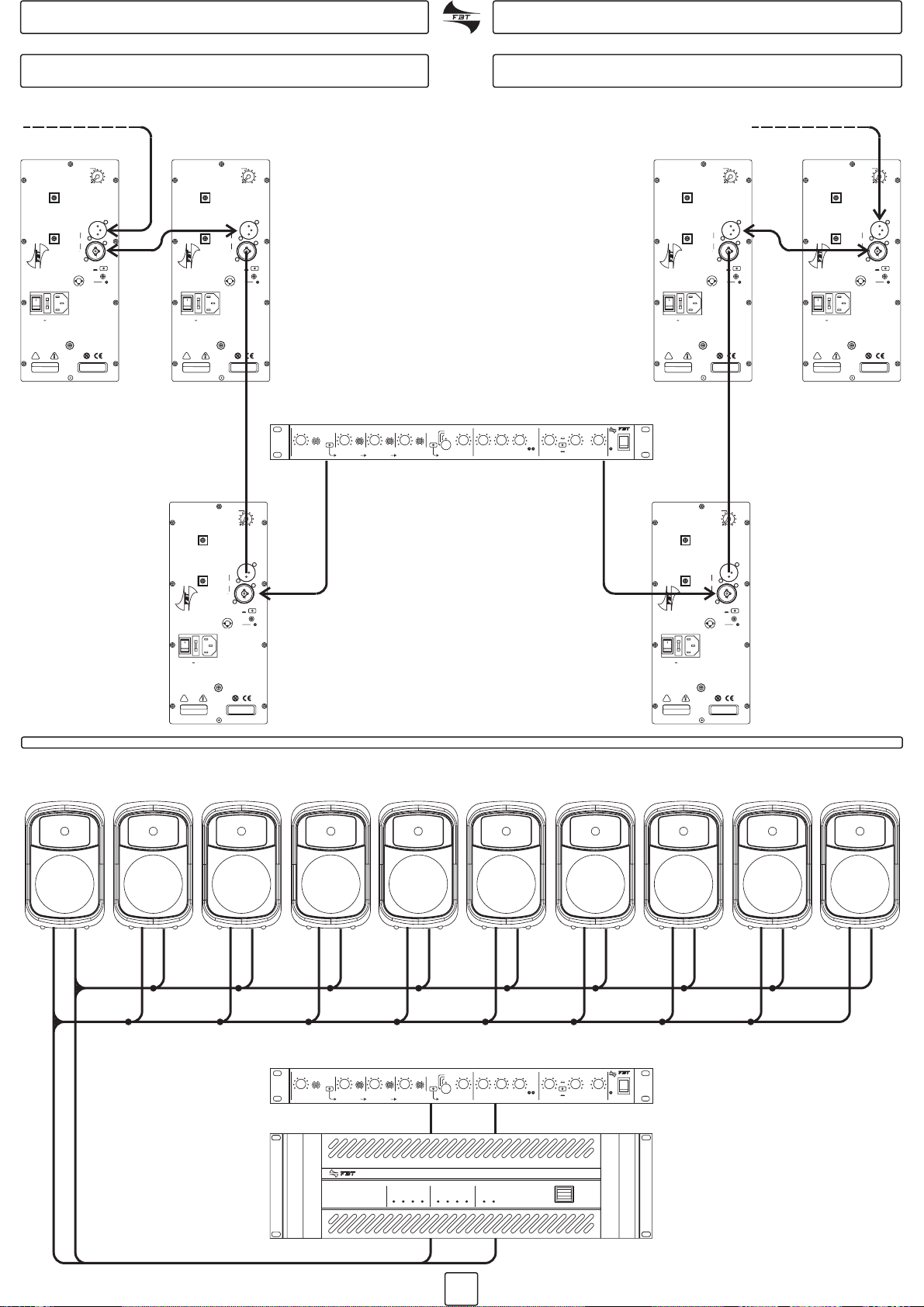
ESEMPI DI COLLEGAMENTO CONNECTION EXAMPLES
EXEMPLES DE CONNEXION ANSCHLUSSBEISPIELE
IN IN
IN IN
IN
OUT OUT
IN
OUT
OUT
STUDIO PRO 9 BT/WT
O
I
MULTICHANNEL POWER AMPLIFIER - MCA 2240A
CH 1 CH 2
SIGNAL CLIP PRT FAILURE SIGNAL CLIP PRT FAILURE EMERG. PWR
0
5
10
0
5
10 0
5
10 0
5
10
0 0 0 0
0
5
10 0
5
10 -15
0
+15 -15
0
+15 0
5
10 0
5
10 0
5
10
PWR
PH
STEREO
MAIN OUT
LR
STEREO
L
PEAK
R
VOLUME BASS HIGH
VOLUMESOURCES
ALL CH
PRIORITY
CH 1
PRIORITY
CHANNEL 1 CHANNEL 2 CHANNEL 3 CHANNEL 4
VOICE VOICE VOICE VOICE
MASTER
M12 X-4
INPUT
MONO
CD
TAPE
TUNER
AUX
MIXER M12 X4
UNITÀ DI POTENZA
POWER AMPLIFIER
AMPLIFICATEUR EXTERNE
ÄUBERER VERSTÄRKER
0
5
10
0
5
10 0
5
10 0
5
10
0 0 0 0
0
5
10 0
5
10 -15
0
+15 -15
0
+15 0
5
10 0
5
10 0
5
10
PWR
PH
STEREO
MAIN OUT
LR
STEREO
L
PEAK
R
VOLUME BASS HIGH
VOLUMESOURCES
ALL CH
PRIORITY
CH 1
PRIORITY
CHANNEL 1 CHANNEL 2 CHANNEL 3 CHANNEL 4
VOICE VOICE VOICE VOICE
MASTER
M12 X-4
INPUT
MONO
CD
TAPE
TUNER
AUX
80+20WPROCESSEDACTIVEMONITOR
80 +20W PROCESSED ACTIVE MONITOR
STUDIO PRO 9BA
O
T 630 mA 250VT630 mA 250V
45VA
230V 50Hz
230V 50Hz
CAUTION
RISK OF ELECTRIC SHOCK
DO NOT OPEN
RISK OF ELECTRIC SHOCK
DO NOT OPEN
|
|
|
<
MADE IN ITALYMADE IN ITALY
Volum e
Out
In
Link
Gnd LiftGnd Lift
Pwr
JACK
1
3
2
X
L
R
X
L
R
XLR
1-Gnd
2-Hot
3-Cold
BUILT IN AMP. :
FREQ. RANGE (@-10dB) :
MAX. SPL (@ 1m) :
SENSITIVITY (@1W, 1m) :
BUILT IN AMP. :
FREQ. RANGE (@-10dB) :
MAX. SPL (@ 1m) :
SENSITIVITY (@1W, 1m) :
80+20W
70Hz - 20kHz
114dB
95 dB
80+20W
70Hz - 20kHz
114dB
95 dB
+12dB line+12dB line
0dB line0dB line
STUDIO PRO 9BA
1968119681 PRO 9BAPRO 9BA
80+20WPROCESSEDACTIVEMONITOR
80 +20W PROCESSED ACTIVE MONITOR
STUDIO PRO 9BA
O
T 630 mA 250VT630 mA 250V
45VA
230V 50Hz
230V 50Hz
CAUTION
RISK OF ELECTRIC SHOCK
DO NOT OPEN
RISK OF ELECTRIC SHOCK
DO NOT OPEN
|
|
|
<
MADE IN ITALYMADE IN ITALY
Volum e
Out
In
Link
Gnd LiftGnd Lift
Pwr
JACKJACK
1
3
2
X
L
R
X
L
R
XLR
1-Gnd
1-Gnd
2-Hot
3-Cold
BUILT IN AMP. :
FREQ. RANGE (@-10dB) :
MAX. SPL (@ 1m) :
SENSITIVITY (@1W, 1m) :
BUILT IN AMP. :
FREQ. RANGE (@-10dB) :
MAX. SPL (@ 1m) :
SENSITIVITY (@1W, 1m) :
80+20W
70Hz - 20kHz
114dB
95 dB
80+20W
70Hz - 20kHz
114dB
95 dB
+12dB line+12dB line
0dB line0dB line
STUDIO PRO 9BA
1968119681 PRO 9BAPRO 9BA
80+20WPROCESSEDACTIVEMONITOR
80 +20W PROCESSED ACTIVE MONITOR
STUDIO PRO 9BA
O
T 630 mA 250VT630 mA 250V
45VA
230V 50Hz
230V 50Hz
CAUTION
RISK OF ELECTRIC SHOCK
DO NOT OPEN
RISK OF ELECTRIC SHOCK
DO NOT OPEN
|
|
|
<
MADE IN ITALYMADE IN ITALY
Volum eVolu me
Out
In
In
Link
Gnd LiftGnd Lift
Pwr
JACKJACK
1
3
2
X
L
R
X
L
R
XLR
1-Gnd
2-Hot
3-Cold
BUILT IN AMP. :
FREQ. RANGE (@-10dB) :
MAX. SPL (@ 1m) :
SENSITIVITY (@1W, 1m) :
BUILT IN AMP. :
FREQ. RANGE (@-10dB) :
MAX. SPL (@ 1m) :
SENSITIVITY (@1W, 1m) :
80+20W
70Hz - 20kHz
114dB
95 dB
80+20W
70Hz - 20kHz
114dB
95 dB
+12dB line+12dB line
0dB line0dB line
STUDIO PRO 9BA
19681 PRO 9BA
PRO 9BA
80+20WPROCESSEDACTIVEMONITOR
80 +20W PROCESSED ACTIVE MONITOR
STUDIO PRO 9BA
O
T 630 mA 250VT630 mA 250V
45VA
230V 50Hz
230V 50Hz
CAUTION
RISK OF ELECTRIC SHOCK
DO NOT OPEN
RISK OF ELECTRIC SHOCK
DO NOT OPEN
|
|
|
<
MADE IN ITALYMADE IN ITALY
Volum e
Out
In
Link
Gnd LiftGnd Lift
PwrPwr
JACK
1
3
2
X
L
R
X
L
R
XLR
1-Gnd
2-Hot
3-Cold
3-Cold
BUILT IN AMP. :
FREQ. RANGE (@-10dB) :
MAX. SPL (@ 1m) :
SENSITIVITY (@1W, 1m) :
BUILT IN AMP. :
FREQ. RANGE (@-10dB) :
MAX. SPL (@ 1m) :
SENSITIVITY (@1W, 1m) :
80+20W
70Hz - 20kHz
114dB
95 dB
80+20W
70Hz - 20kHz
114dB
95 dB
+12dB line+12dB line
0dB line0dB line
STUDIO PRO 9BA
19681 PRO 9BA
PRO 9BA

10
SPECIFICHE TECNICHE TECHNICAL SPECIFICATIONS
CARACTÉRISTIQUES TECHNIQUES TECHNISCHE DATEN
STUDIO
PRO 9 B/W
STUDIO
PRO 9 B/W
STUDIO
PRO 9 BT/WT
STUDIO
PRO 9 BT/WT
STUDIO
PRO 9 BA
STUDIO
PRO 9 BA
Configurazione
Configurations
Konfiguration
Configuration vie
way
voies
wege
222
Amplificatore consigliato
Amplificateur recommandé
Recommended amplifier
Empfohlene Endstufe
W rms 120 80 ---
Potenza lungo termine
Long term power
Potenza breve termine
Short term power
Impedenza nominale
Impédance nominale
Nominal impedance
Nennimpedanz
Trasformatore di linea
Line transformer
Risposta in frequenza
Réponse en fréquence
Frequency response
Frequenzgang
Unità basse frequenze
Unité basses fréquences
Low frequency woofer
Tieftoneinheit
Unità alte frequenze
Unité hautes fréquences
High frequency driver
Hochtoneinheit
Sensibilità
Sensibilité
Sensitivity
Empfindlichkeit
SPL massimo
SPL max
Max SPL
Max schalldruck
Dispersione
Dispersion
Dispersion
Abstrahlwinkel
Connettori di ingresso
Connecteurs d’entrée
Input connectors
Eingangsanschlüsse
Peso
Poids
Weight
Gewicht
Dimensioni
Dimensions
Dimensions
Abmessungen
W
W
ohm
V
@-6dB
mm
mm
@1W, 1m dB
dB
HxV
kg
mm
60 --- ---
240 --- ---
8--- ---
70/100 ---
---
80Hz - 20kHz 80Hz - 20kHz 70Hz - 20kHz
1 x 200 1 x 200 1 x 200
1 x tweeter
+
tromba
1 x tweeter
+
tromba
95,5 95,5 95
116,5 114,5 115
90° x 60° 90° x 60° 90° x 60°
terminal block terminal block combo/XLR
4,8 4,8 5,4
255 x 415 x 245
Amplificatore interno
Amplificateur intégré
Built-in amplifier
Endstufe intern
W rms --- --- 80+20
255 x 415 x 245
1 x tweeter
+
tromba
255 x 415 x 245

11
La diffusione del suono in un ambiente ha per scopo
una soddisfacente audizione da parte di un certo
numero di persone ed è legata a diversi fattori
dipendenti dall’ambiente stesso ( forma, volume,
ecc.), dal numero e dalla posizione degli ascoltatori,
dalla natura della sorgente sonora (esecuzioni
musicali e parlato dal vivo o riprodotti da
registrazione), dal livello di rumore presente
nell’ambiente.
I sistemi di diffusori più usati:
a) quello che potremmo chiamare classico, costituito
da due diffusori separati
b) che è dotato di un terzo diffusore a larga banda che
riproduce, a livello più ridotto degli altri due, entrambi i
canali
c) analogo al precedente ma con la differenza che il
diffusore centrale riproduce solo le frequenze basse
(subwoofer e satelliti)
d) quello dei diffusori che non irradiano direttamente
ma per riflessione contro la parete delle stanze
La qualità sonora e il volume di un diffusore dipendono
da tre fattori: la sua efficienza, le sue dimensioni e il
suo utilizzo in combinazione con altri diffusori.
L’efficienza, cioè la qualità di energia prodotta
dall’amplificatore trasformata in suono, determina il
volume che si può ottenere da un amplificatore di una
data potenza. I diffusori molto efficienti possono far si
che un amplificatore da 50 watt dia maggior volume di
uno da 100 watt usato con diffusori meno efficienti.
Una delle caratteristiche elettriche di un diffusore è
l’impedenza (la resistenza offerta alla corrente
alternata). Sia la resistenza che l’impedenza si
misurano in ohm; l’impedenza varia al variare della
frequenza quindi ne consegue che le diverse
frequenze possono essere rese con una potenza
diversa.
In base a questi esempi di accoppiamento si può
affermare che le impedenze uguali sono chiaramente
abbinabili fra loro, mentre un finale che ad esempio ha
una uscita di 8 ohm può essere collegato ad una cassa
che abbia l’entrata a 16 ohm. Questo vale su ogni
canale di uscita del finale.
FINALE
8 OHM
16 OHM
8 OHM
4 OHM
CASSA
8 OHM
16 OHM
16 OHM
8 OHM
BREVI CENNI DI ACUSTICA BRIEF NOTES ON ACOUSTICS
Sound diffusion throughout a room serves to
distribute sound signals to a given audience and the
results are dependent on several ambient factors
(room shape, volume, etc.), the number of people
present and their precise location, the type of sound
source (live or recorded music or speech), and the
level of background ambient noise.
Common types of speaker systems:
a) the "classic" system composed of two separately
sited speakers
b) equipped with a full-frequency speaker that
reproduces both channels at a lower level than the left
and right channels
c) similar system but with the difference that the
central speaker only reproduces low frequencies
(subwoofer and satellites)
d) system in which the sound from speakers is
reflected off a wall of the room rather than being
transmitted directly to the audience
The sound quality and volume of a speaker depend on
three factors: its efficiency, its dimensions and its use
in combination with other speakers. Efficiency, or the
quantity of energy produced by the amplifier
transformed into sound, determines the volume that
can be obtained from an amplifier of given power
rating. Very efficient speakers can result in a 50-watt
amplifier producing a louder volume than a 100-watt
amplifier used with less efficient speakers.
One of the electrical characteristics of a speaker is its
impedance (resistance to the passage of alternating
current). Both resistance and impedance are
measured in ohms; impedance varies at different
frequencies so it follows that different frequencies can
be delivered with different power levels.
In some cases confusion may arise when combining
impedance values of power amplifiers with those of
loudspeakers:
In accordance with these example matches it can be
stated that identical impedances are clearly
compatible, while a power amplifier with an 8 ohm
output can be connected to a loudspeaker with a 16
ohm input. This applies to all the power amplifier
output channels.
POWER AMP.
8 OHM
16 OHM
8 OHM
4 OHM
BOX
8 OHM
16 OHM
16 OHM
8 OHM

12
NOTIONS D’ACOUSTIQUE KURZE HINWEISE ZUR AKUSTIK
La diffusion du son dans un milieu fermé a pour but de
garantir une audition satisfaisante de la part d'un
certain nombre de personnes et est fonction de
différents facteurs dépendant du milieu proprement
dit (forme, volume, etc.), du nombre et de la position de
l'audience, de la nature de la source sonore
(exécutions musicales et parlées en directe ou
produites par enregistrement), du niveau de bruit
présent dans le milieu.
Les systèmes de haut-parleurs les plus communément
utilisés sont :
a) le système classique, comportant deux haut-
parleurs séparés
b) le système équipé d'un troisième haut-parleur à
large bande, reproduisant les deux canaux à un niveau
plus réduit que les deux autres
c) le système analogue au précédent mais avec un
haut-parleur central qui ne reproduit que les basses
fréquences (subwoofer et satellites)
d) le système de haut-parleurs avec diffusion par
réflexion contre les parois des pièces contrairement à
la diffusion directe
La qualité et le volume sonores d'un haut-parleur
dépendent de trois facteurs : son efficacité, ses
dimensions et son emploi conjointement à d'autres
haut-parleurs. L'efficacité, c'est à dire la qualité
d'énergie produite par l'amplificateur et transformée
en son, détermine le volume sonore possible fourni
par un amplificateur de puissance donnée. Les haut-
parleurs très efficaces peuvent faire en sorte qu'un
amplificateur de 50 watts offre plus de volume qu'un
100 watts utilisé avec des haut-parleurs moins
efficaces.
Une des caractéristiques électriques d'un haut-parleur
est l'impédance (la résistance opposée au courant
alternatif). Aussi bien la résistance que l'impédance se
mesurent en ohm ; l'impédance varie en fonction de la
fréquence, ce qui signifie que les différentes
fréquences peuvent être rendues à une puissance
différente.
Dans certains cas, il est possible de faire confusion
sur les accouplements d'impédances entre les
amplificateurs finaux et les enceintes :
Sur la base de ces exemples d'accouplements, il est
possible d'affirmer que des impédances identiques
peuvent clairement être accouplées entre elles, tandis
qu'un ampli final qui a une impédance de sortie de 8
ohms, par exemple, ne peut pas être connecté à une
enceinte dont l'impédance d'entrée est de 16 ohms.
Cette règle s'applique à chaque canal de sortie de
l'ampli final.
FINALE DE PUISSANCE
8 OHM
16 OHM
8 OHM
4 OHM
BOX
8 OHM
16 OHM
16 OHM
8 OHM
Die Verbreitung des Klangs in einer Umgebung hat den
Zweck, von einer gewissen Anzahl von Personen auf
zufriedenstellende Weise gehört zu werden und hängt
von verschiedenen Faktoren der Umgebung selbst ab
(Form, Lautstärke usw.), von der Anzahl und der
Raumverteilung der Zuhörer, von der Art der
Klangquelle (musikalische Darbietungen und
Sprachübertragung, live oder durch Wiedergabe von
Aufnahmen), vom Geräuschpegel in der Umgebung.
Die meistverwendeten Lautsprechersysteme:
a) Die sogenannten "Klassiker" bestehen aus zwei
separaten Lautsprechern
b) Systeme mit einem dritten Breitbandlautsprecher,
der beide Kanäle in reduzierter Form reproduziert
c) Analog zu vorherigem Typ mit dem Unterschied,
dass der zentrale Lautsprecher nur tiefe Frequenzen
wiedergibt (Subwoofer oder Satellit)
d) Reflexlautsprecher, die nicht direkt, sondern über
den von der Zimmerwand zurückgeworfenen Ton
ausstrahlen
Die Klangqualität und die Lautstärke eines
Lautsprechers hängen von drei Faktoren ab: seiner
Leistungsfähigkeit, seinen Abmessungen und seinem
Gebrauch in Verbindung mit anderen Lautsprechern.
Die Leistungsfähigkeit, also die Qualität der erzeugten
und vom Verstärker in Ton umgewandelten Energie,
bestimmt die Lautstärke, die man von einem Verstärker
mit einer gegebenen Leistung erreichen kann.
Besonders leistungsstarke Lautsprecher können mit
einem 50 Watt-Verstärker mehr Lautstärke
hervorbringen, als ein 100 Watt-Verstärker mit weniger
leistungsstarken Lautsprechern.
Eines der elektrischen Merkmale eines Lautsprechers
ist die Impedanz (der gebotene Widerstand gegen den
Wechselstrom). Sowohl der Widerstand als auch die
Impedanz werden in Ohm gemessen; die Impedanz
ändert sich frequenzabhängig, d.h. verschiedene
Frequenzen können mit verschiedener Leistung
wiedergegeben werden.
In einigen Fällen kann es zu Schwierigkeiten bei der
Kombination der Impedanzen zwischen Endstufen und
Boxen kommen:
Auf der Grundlage dieser Beispiele kann man
feststellen, dass die Kombination gleicher
Impedanzen eindeutig möglich ist, während
beispielsweise eine Endstufe mit einem Ausgang von 8
Ohm an eine Box angeschlossen werden kann, die
über einen 16 Ohm Eingang verfügt. Das gilt für jeden
Ausgangskanal der Endstufe.
LEISTUNGSVERSTÄRKER
8 OHM
16 OHM
8 OHM
4 OHM
BOX
8 OHM
16 OHM
16 OHM
8 OHM

13
Adattare l’impedenza di uscita del finale di potenza a
quella degli speakers significa fare in modo che tutta
l’energia emessa dal finale venga trasferita alle casse
senza perdita di segnale e quindi far funzionare il
sistema al meglio delle sue possibilità (ed evitare
danni); una cassa con impedenza superiore a quella
del finale può essere utilizzata a scapito della potenza,
mentre è bene evitare collegamenti con casse che
hanno impedenza minore a quella del finale di potenza.
Usando sistemi più complessi (ad esempio più
speaker collegati allo stesso finale) bisogna fare in
modo che il valore totale dell’impedenza degli
altoparlanti sia corrispondente a quella presente sul
finale.
Possiamo avere due tipi di collegamento: in serie o in
parallelo.
Collegare in serie due altoparlanti significa unire un
terminale positivo ed uno negativo dei due e collegare
all’amplificatore i rimanenti due terminali rimasti
scollegati. I loro valori si sommano: per esempio, due
altoparlanti da 8 ohm in serie danno 16 ohm.
Quando gli altoparlanti sono collegati in parallelo, i
terminali dello stesso segno sono uniti tra loro. Per
ottenere il valore totale bisogna utilizzare una formula,
indicando con R1 ed R2 i valori di due altoparlanti, ed
eseguire. (R1 x R2 ) / ( R1 + R2 ). Con due altoparlanti
da 8 ohm, per esempio, avremo:
(8x8) / (8+8) = 64/16 = 4 ohm. In pratica collegando
due altoparlanti uguali in parallelo il valore si dimezza.
Un diffusore può essere utilizzato sia in impianti di
sonorizzazione a tensione costante sia in impianti ad
impedenza costante.
IMPIANTI A TENSIONE COSTANTE
(1) La tensione di ingresso selezionata sul diffusore
deve corrispondere con la tensione selezionata
sull’uscita dell’amplificatore
(2) La somma delle potenze nominali di tutti i diffusori
collegati non deve superare quella dell’amplificatore
IMPIANTI AD IMPEDENZA COSTANTE
(1) L’impedenza di carico complessiva di tutti i diffusori
collegati non deve essere inferiore all’impedenza
selezionata sull’uscita dell’amplificatore, per non
rischiare di danneggiare seriamente quest’ultimo
(2) La somma delle potenze nominali di tutti i diffusori
collegati non deve essere inferiore a quella
dell’amplificatore
(3) La lunghezza dei cavi di collegamento deve essere
ridotta al minimo
BREVI CENNI DI ACUSTICA BRIEF NOTES ON ACOUSTICS
Adapting the output impedance of the power amplifier
to the loudspeaker input impedance means that all the
energy from the amplifier will be transferred to the
speakers with no signal losses, so that the system
functions in optimum conditions (and the risk of
damage is minimised); a loudspeaker of higher
impedance than the power amplifier can be used
although this will result in a power reduction;
loudspeakers of lower impedance than the power
amplifier output impedance should not be connected.
If more complex systems (e.g. several speakers
connected to the same power amplifier) are adopted, it
must be ensured that the overall speaker impedance
value corresponds to the power amplifier output
impedance.
There are two possible connection systems: series or
parallel.
Connecting two speakers in series means connecting
the positive terminal of one speaker to the negative
terminal of the other and then connecting the two
remaining unconnected terminals to the amplifier. In
this case the impedance values are summed: e.g. two 8
ohm speakers connected in parallel present a 16 ohm
load.
To connect two speakers in parallel simply
interconnect the two sign speaker terminals. To obtain
the total value in this case a calculation is required
wherein R1 and R2 are the loudspeaker values and the
following formula is resolved: (R1 x R2 ) / ( R1 + R2 ).
For example, with two 8-ohm speakers, we would have:
(8x8) / (8+8) = 64/16 = 4 ohm. In practice, when two
identical speakers are connected in parallel the
impedance value is halved.
A speaker can be used both in constant voltage sound
systems and constant impedance systems.
CONSTANT VOLTAGE SYSTEMS
(1) The input voltage selected on the speaker must
correspond to the voltage selected on the amplifier
output
(2) The sum of the nominal power values of all the
connected speakers must not exceed that of the
amplifier
CONSTANT IMPEDANCE SYSTEMS
(1) The total load impedance of all the connected
speakers must be no less than the impedance selected
on the amplifier output to avoid the risk of serious
damage to the amplifier
(2) The sum of nominal power values of all connected
speakers must be no less than that of the amplifier
(3) Connection cable lengths must be kept to the
indispensable minimum

14
NOTIONS D’ACOUSTIQUE KURZE HINWEISE ZUR AKUSTIK
Adapter l'impédance de sortie de l'ampli final de
puissance à celle des haut-parleurs signifie faire en
sorte que toute l'énergie émise par l'ampli final soit
transférée aux enceintes sans perte de signal et donc
tirer le meilleur parti du système (tout en évitant des
dommages conséquents à un mauvais accouplement)
; il est possible d'utiliser un haut-parleur avec une
impédance supérieure à celle de l'ampli final, cela au
détriment de la puissance ; par contre il convient
d'éviter les connexions avec haut-parleurs ayant une
impédance inférieure à celle de l'ampli final de
puissance.
Dans les systèmes plus complexes (par exemple
plusieurs haut-parleurs connectés au même ampli
final), il est nécessaire de faire en sorte que la valeur
totale de l'impédance des haut-parleurs corresponde à
celle sur la sortie de l'ampli final.
Deux types de connexion sont possibles : en série ou
en parallèle.
Connecter en série deux haut-parleurs signifie unir une
borne positive de l'un à la négative de l'autre et
connecter à l'amplificateur les deux bornes restantes.
Leurs valeurs s'ajoutent : par exemple, deux haut-
parleurs de 8 ohms en série auront au total une
impédance de16 ohms.
Quand les haut-parleurs sont connectés en parallèle,
les bornes du même signe sont unies entre elles.
Pour obtenir la valeur totale de l'impédance, il faut
utiliser la formule, (R1 x R2 ) / ( R1 + R2 ), R1 et R2 étant
les valeurs d'impédance des deux haut-parleurs, et la
calculer. Par exemple, avec deux haut-parleurs de 8
ohms, nous aurons :
(8x8) / (8+8) = 64/16 = 4 ohms. En pratique, en
connectant deux haut-parleurs identiques en parallèle,
la valeur est réduite de moitié.
Un haut-parleur peut être utilisé aussi bien dans des
installations de sonorisation à tension constante que
dans des installations à impédance constante.
INSTALLATIONS À TENSION CONSTANTE
(1) La tension d'entrée sélectionnée sur le haut-parleur
doit correspondre à la tension sélectionnée à la sortie
de l'amplificateur.
(2) La somme des puissances nominales de tous les
haut-parleurs ne doit pas dépasser celle de
l'amplificateur.
INSTALLATIONS À IMPÉDANCE CONSTANTE
(1) L'impédance de charge totale de tous les haut-
parleurs branchés ne doit pas être inférieure à
l'impédance sélectionnée à la sortie de l'amplificateur,
pour ne pas risquer d'endommager sérieusement ce
dernier.
(2) La somme des puissances nominales de tous les
haut-parleurs branchés ne doit pas dépasser celle de
l'amplificateur.
(3) La longueur des câbles de connexion doit être
réduite au minimum.
Durch Anpassung von der Ausgangsimpedanz der
Endstufe an die der Lautsprecher wird dafür gesorgt,
dass die gesamte von der Endstufe ausgegebene
Energie ohne Signalverlust an die Boxen übertragen
wird. Dadurch wird das Potenzial des Systems optimal
genutzt und Schäden vorgebeugt; eine Box mit
höherer Impedanz als die Endstufe kann verwendet
werden, führt jedoch zu Einbußen bei der Leistung,
während der Anschluss von Boxen mit geringerer
Impedanz als die Leistungsendstufe vermieden
werden sollte.
Bei der Anwendung komplexerer Systeme (z. B.
mehrere Lautsprecher, die an dieselbe Endstufe
angeschlossen sind) muss dafür gesorgt werden, dass
der Gesamtwert der Impedanz der Lautsprecher dem
der Endstufe entspricht.
Es gibt zwei Anschlussarten: Parallel- und
Serienschaltung.
Die Serienschaltung bei zwei Lautsprechern besteht
darin, jeweils eine positive und eine negative
Anschlussklemme der beiden miteinander zu
verbinden, während die beiden verbleibenden
Anschlussklemmen an den Verstärker angeschlossen
werden. Die Werte der beiden addieren sich: z. B. zwei
Lautsprecher mit 8 Ohm ergeben in Serienschaltung
eine Leistung von 16 Ohm.
Bei der Parallelschaltung werden jeweils die
Anschlussklemmen der beiden Lautsprecher mit
demselben Vorzeichen untereinander verbunden. Um
den Gesamtwert zu erhalten, muss eine Formel
verwendet werden, die mit R1 und R2 die Werte zweier
Lautsprecher angibt. (R1 x R2 ) / ( R1 + R2 ). Mit zwei 8
Ohm Lautsprechern erhalten wir beispielsweise:
(8x8) / (8+8) = 64/16 = 4 Ohm. Praktisch halbiert sich
also der Wert bei der Parallelschaltung zweier
Lautsprecher.
Ein Lautsprecher kann sowohl in Audioanlagen mit
konstanter Spannung als auch in Anlagen mit
konstanter Impedanz benutzt werden.
ANLAGEN MIT KONSTANTER SPANNUNG
(1) Die am Lautsprecher gewählte Eingangsspannung
muss der am Ausgang des Verstärkers gewählten
Spannung entsprechen
(2) Die Summe der Nennleistungen aller
angeschlossenen Lautsprecher darf die des
Verstärkers nicht übersteigen
ANLAGEN MIT KONSTANTER IMPEDANZ
(1) Die Gesamtimpedanz der Last aller
angeschlossenen Lautsprecher darf nicht unterhalb
der am Ausgang des Verstärkers gewählten Impedanz
liegen, um schwere Schäden am Verstärker zu
vermeiden
(2) Die Summe der Nennleistungen aller
angeschlossenen Lautsprecher darf nicht niedriger
sein als die des Verstärkers
(3) Die Verbindungskabel müssen so kurz wie möglich
sein
This manual suits for next models
4
Table of contents
Other Fbt Speakers manuals

Fbt
Fbt STUDIO 2 BT User manual

Fbt
Fbt rhox CS4100/EN Series User manual

Fbt
Fbt X PRO 112 MA User manual

Fbt
Fbt SHADOW 105T User manual

Fbt
Fbt Muse 210LND User manual

Fbt
Fbt COLUMN VERTUS CLA 403T User manual

Fbt
Fbt SHADOW 108CT User manual

Fbt
Fbt CS 3000 Series User manual

Fbt
Fbt PSR 212 User manual

Fbt
Fbt PSR 212m User manual


Popular Speakers manuals by other brands


JVC
JVC XS-N5320PBA manual

American Audio
American Audio ELS PA10 User guide and reference manual

Furrion
Furrion LIT FBS012NVP-BL Quick start guide & user manual

Philips
Philips HTB5150K quick start guide

ARCHITETTURA SONORA
ARCHITETTURA SONORA ICARUS quick start guide

Goodis
Goodis Pink Xplosion instruction manual


