Fbt CLA 118SA User manual

PROCESSED ACTIVE SUBWOOFER


1
3
5
6
7
8
9
10
12 / 13
14
CONFIGURAZIONI CARDIOIDI 11
CARDIOID CONFIGURATIONS
CONFIGURATIONS CARDIOÏDES
KARDIOIDE KONFIGURATIONEN
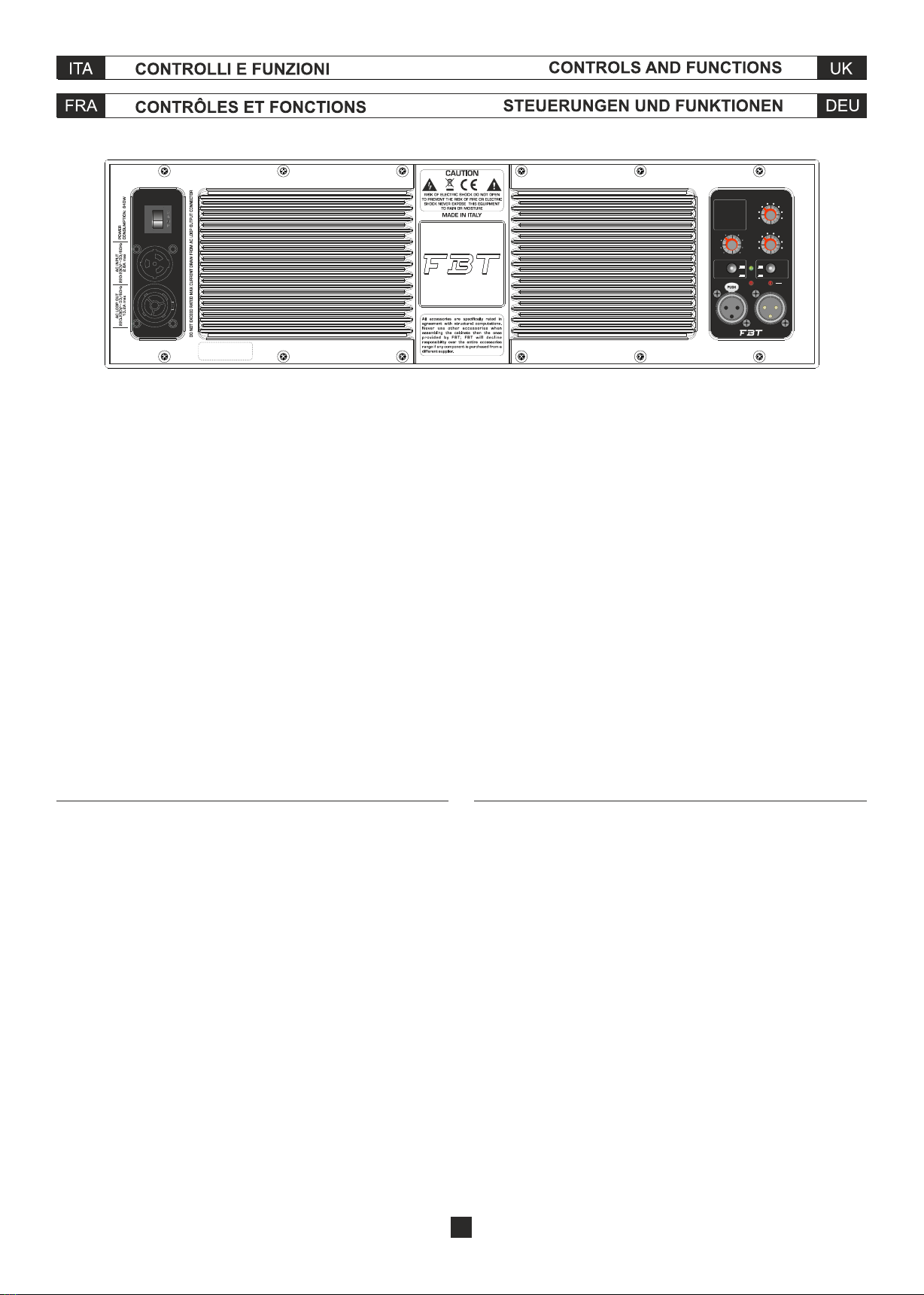
SEZIONE AMPLIFICAZIONE E CONTROLLO
AMPLIFICATION AND CONTROL SECTION
SECTION D’AMPLIFICATION ET DE CONTRÔLE
VERSTÄRKER-UND STEUERSEKTION
4
1
3
5
6
7
8
9
10
12 / 13
14
11
4
2
3
5
6
7
8
9
10
12 / 13
14
11
4
2
3
5
6
7
8
9
10
12 / 13
14
11
4
1

2

CLA 118SA è un subwoofer in multistrati di betulla con woofer B&C
da 460mm in bass reflex dotato di ampia porta di accordo a flusso
d'aria laminare per ridurre al minimo fenomeni di turbolenza.
Anche per questo modello il modulo di amplificazione è in
pressofusione in alluminio a convezione naturale da 1200W in
Classe D con alimentatore switching; dispone di un processore
DSP con la funzione di filtraggio, equalizzazione e protezione.
Pensato per estendere le performance del CLA 406.2A soprattutto
in applicazioni live, dove funge da supporto e base per la colonna
CLA 406.2A.
The CLA 118SA is a subwoofer in birch plywood with a 18" woofer
from B&C in a bass reflex port with an extensive laminar airflow,
minimizing turbulence and power compression. The Class D
switchin power amplifier module is constructed in die-cast
aluminum with natural convection and is rated at 1200W. Onboard
DSP also offers functions such as filtering, equalization and
protection.
When you need to extend the performance of the CLA 406.2A,
especially in live applications, the CLA 118SA acts as a support and
base for the CLA 406.2A column that can be applied, via optional
hardware, with M20 points positioned on the top of the sub.
3
CLA 118SA est un subwoofer en multicouches de bouleau avec
woofer B&C de 460mm en bass-reflex, équipé d'un grand évent
d'accord avec écoulement de l'air lamellaire afin de réduire plus que
possible les phénomènes de turbulence.
Pour ce modèle aussi le module amplificateur est sous pression en
aluminium à convection naturelle de 1200W en Classe D avec
alimentateur de type « switching » ; il présente aussi un processeur
DSP avec la fonction de filtrage, égalisation et protection.
Il a été conçu pour élargir les performances du CLA 406.2A, surtout
en cas de performances « live », où il sert de support et de base
pour la colonne CLA 406.2A.
CLA 118SA ist ein Subwoofer aus Birkenschichtholz mit 460mm-
B&C- Woofer im Bassreflex Design ausgestattet mit einem weiten
gestimmten Tiefenport mit laminarer Luftströmung zur
Reduzierung auf ein Minimum von Turbulenzphänomenen.
Auch bei diesem Modell ist das Verstärkermodul aus Aluminium-
Druckguss mit 1200W-Eigenkonvektion in der D-Klasse mit
Switching -Netzgerät; es verfügt über einen DSP Prozessor mit
Filter-, Equalize- und Schutzfunktion.
Konzipiert zur Erweiterung der Performance von CLA 406.2A vor
allem bei Live-Anwendungen, wo er als Stütze und Sockel für die
CLA 406.2A-Säule dient.
ON
GND
LIFT PHASE
180˚
0˚
+6dB
0
0
0
0
0.5
11.5 22.5
3
3.5
PRESETLEVEL
DELAY
mt.
1
2
3
45
6
7
8
IN LINK
PEAK
OFF
ON
LMT
PRT
VERTUS CLA 118SA
2-Deep
3-Punch
4-DJ
CARDIOID REAR:
5-Original
6-Deep
7-Punch
8-DJ
1-Original
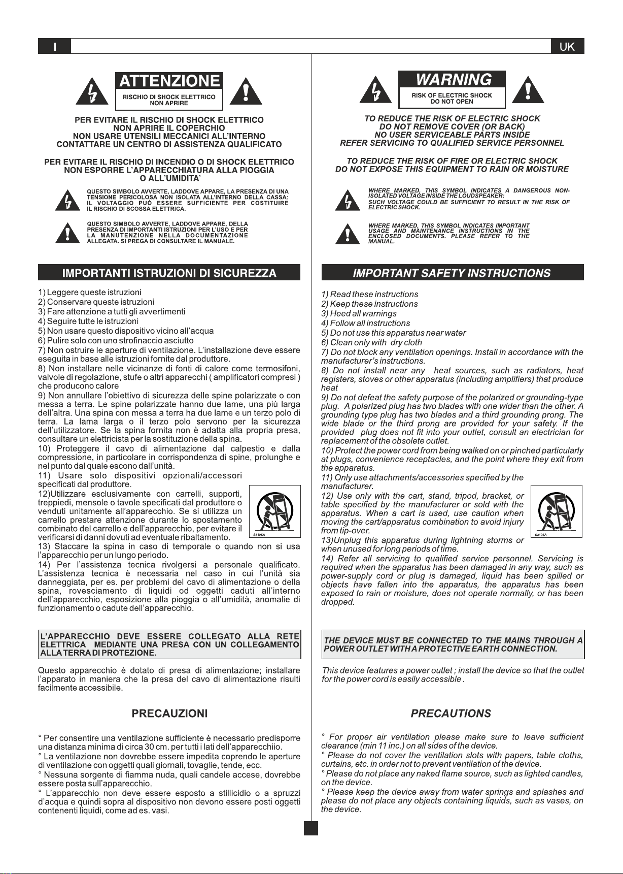
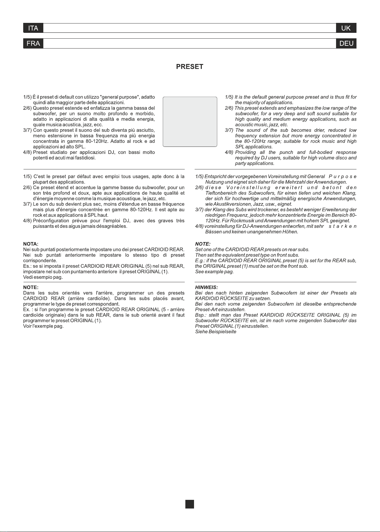
• Proteggere il modulo dall'umidità
• Non tentare in alcun modo di aprire l'amplificatore
• In caso di malfunzionamento interrompere
immediatamente l ' a l i m e n t a z i o n e ,
scollegando il modulo dalla rete e contattare un
riparatore autorizzato
• Protect the module from humidity
• Never try to open the amplifier
• In case of malfunction immediately cut off the power
supply by disconnecting the module from the mains,
then contact an authorised repairman
• Protéger le module de l'humidité
• Ne tenter en aucune façon d'ouvrir l'amplificateur
• En cas de dysfonctionnement couper immédiatement
l'alimentation, en débranchant le module du réseau, et
contacter un réparateur agréé
• Das Modul muss vor Feuchtigkeit geschützt werden
• Es darf keinesfalls versucht werden, den Verstärker zu
öffnen
• Bei Funktionsstörungen sofort die Stromversorgung
unterbrechen, indem der Netzstecker des Moduls
abgezogen wird. Dann Kontakt mit einer autorisierten
Reparaturwerkstatt aufnehmen
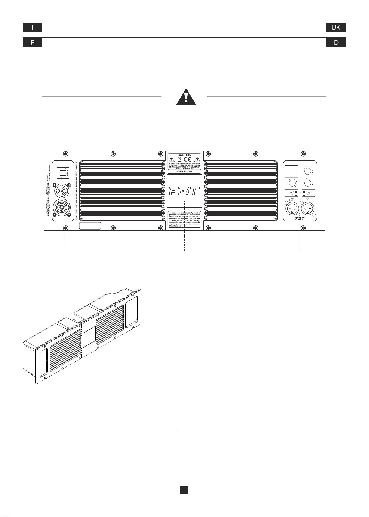
Il diffusore dispone di un modulo amplificatore in Classe D ad alta efficienza
con alimentatore switching inserito in un guscio in pressofusione di
alluminio. Questo permette di proteggere l'elettronica da polvere, evitare
qualsiasi perdita d'aria dai componenti meccanici che causerebbe
fastidiosi rumori, massimizzare la dissipazione di calore sfruttando anche
la ventilazione del woofer evitando l'uso di ventole di raffreddamento.
The system display a high-efficiency Class D power amplifier module with
switching power supply enclosed in a die-cast aluminium chassis. This
permits to protect the electronics against dust, avoid any air loss through
the controls which would cause annoying noises, maximize healt loss by
using the woofer ventilation instead of a cooling fan.
Le diffuseur présentent un module amplificateur en Classe D à haute
efficacité avec alimentateur de type switching mis en boîte dans une
enveloppe sous pression en aluminium. Cette enveloppe permet de
protéger la partie électronique de la poussière, d'éviter toute perte d'air des
contrôles qui causerait des bruits ennuyeux, de maximiser la dissipation de
la chaleur en exploitant même la ventilation du woofer et en évitant l'emploi
de ventilateursn de refroidissement.
Die Systeme verfügen über ein Verstärker Modul in Klasse D mit
eingekapseltem Switching-Netzgerät aus Aluminiumdruckgussgehäuse.
Dies schützt die Elektronik vor Staub, vermeidet Luftverlust an den
Regelungen, der lästigen Lärm produzieren würde, und maximiert den
Wärmeverlust, indem auch die Wooferlüftung genutzt wird und zusätzliche
Abkühlräder vermieden werden.
SEZIONE AMPLIFICAZIONE E CONTROLLO AMPLIFICATION AND CONTROL SECTION
SECTION D'AMPLIFICATION ET DE CONTRÔLE VERSTÄRKER - UND STEUERSEKTION
SEZIONE DI INPUT E DI CONTROLLO
INPUT AND CONTROL SECTION
SECTION D'INPUT ET DE CONTRÔLE
EINGANGS- UND STEUERSEKTION
AMPLIFICATORE
AMPLIFIER
AMPLIFICATEUR
VERSTÄRKER
SEZIONE ALIMENTAZIONE
POWER SUPPLY SECTION
SECTION D'ALIMENTATION
NETZEIL
4
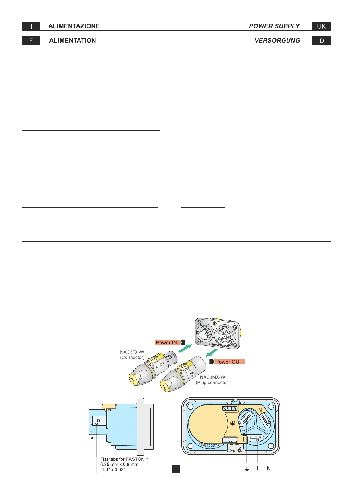
ALIMENTAZIONE 230V:
Per l'alimentazione elettrica il modello VERTUS CLA è fornito di una presa
Neutrik PowerCon cable duplex con ingresso ed uscita.
ATTENZIONE: non sostituire la spina in dotazione del cavo di alimentazione
con un'altra spina, in quanto il cavo di alimentazione è in grado di supportare
una corrente massima di 16A
ALIMENTAZIONE 120V:
Se la richiesta complessiva di corrente è inferiore a 15A utilizzare il cavo di
alimentazione in dotazione. Se la richiesta complessiva di corrente è
superiore a 15A ed inferiore a 20A utilizzare un cavo di alimentazione
AWG12 SJT VW1 con una spina di corrente nominale superiore o uguale a
30A.
IL CAVO E LA SPINA DEVONO ESSERE CERTIFICATI "UL" O "CSA"
POWER SUPPLY 230V:
For power supply VERTUS CLA model features a Neutrik PowerCon cable
duplex with input and output.
CAUTION: never replace the plug of the power cord supplied since the
power cord can only support a maximum current of 16A.
POWER SUPPLY 120V:
If the total current demand does not exceed 15A use the power cable
supplied. If the total current demand is between 15A and 20A user the power
cable AWG12 SJT VW1 with plug rated current equal or greater than 30A.
THE CABLE AND THE PLUG MUST HOLD THE "UL" OR "CSA"
CERTIFICATION.
ALIMENTATION 230V:
Pour l'alimentation électrique la série VERTUS CLA est équipée de prise
Neutrik PowerCon cable duplex avec entrée et sortie.
ATTENTION: ne pas remplacer la fiche fournie du câble d'alimentation par
une autre fiche, puisque le câble d'alimentation est en mesure de soutenir
un courant maximum de 16A.
ALIMENTATION 120V:
Si la demande totale de courant ne dépasse pas 15A utiliser le câble
d'alimentation fourni. Si la demande totale de courant dépasse 15A mais
elle est inférieure à 20A utiliser un câble d'alimentation AWG12 SJT VW1
avec une fiche au courant nominal supérieur ou égal à 30A.
LE CÂBLE ET LA FICHE DOIVENT ÊTRE CERTIFIÉS "UL" O "CSA"
STROMVERSORGUNG 230V:
Für die Stromversorgun sind die Modelle VERTUS CLA mit einem Stecker
Neutrik PowerCon cable duplex mit Ein-und Ausgang geliefert.
ACHTUNG: das mitgelieferte Kabel darf nur dann benutzt werden, wenn die
gesamte Stromaufnahme unter 16A liegt.
STROMVERSORGUNG 120V:
Ist die gesamte Stromanfrage unter 15A bitte das mitgelieferte
Versorgungskabel verwenden. Ist die gesamteStromanfrage über 15A aber
unter 20A ein Versorgungskabel AWG12 SJT VW1 mit einem Stecker für
Nennstrom über oder gleich 30A verwenden.
DAS KABEL UND DER STECKER MÜSSEN "UL" ODER "CSA"
ZERTIFIZIERT SEIN.
OPERATING AND ASSEMBLY INSTRUCTION NAC3PX POWERCONUSO E ISTRUZIONI DI MONTAGGIO POWERCON NAC3PX
INSTALLATIONS-UND HINWEISE NAC3PX POWERCONUTILISATION ET INSTALLATION POWERCON NAC3PX
The "PowerCon True 1" system is certified as connector with breaking
capacity according IEC 60320, VDE 0625. It is intended for use as appliance
couplers and interconnection couplers. It serves to supply power to an
appliance and from an appliance to another equipment. To be installed by
qualified person only.
Il sistema "PowerCon True 1" è certificato come connettore con capacità di
interruzione in conformità alla norma IEC 60320, VDE 0625. È adatto per
collegamento di dispositivi e interconnessioni. Serve ad alimentare un
dispositivo, oppure a fornire alimentazione da un dispositivo ad un'altra
apparecchiatura. Dovrà essere installato esclusivamente da personale
qualificato.
Das System "PowerCon True 1" ist als Schaltnetzteil mit Schaltleistung in
Übereinstimmung mit IEC 60320, VDE 0625 zertifiziert. Es ist für die
Verwendung als Gerätestecker und als Netzweiterverbindung gedacht. Es
dient dazu, ein Gerät mit Strom zu versorgen und auch der
Stromversorgung von einem Gerät zu einer anderen Ausstattung. Es darf
nur von qualifiziertem Personal installiert werden.
Le système « PowerCon True 1 » est certifié comme connecteur avec
pouvoir de coupure selon les normes CEI 60320, VDE 0625. Il a été conçu
pour l'emploi en tant que connecteur d'appareils et connecteur
d'interconnexion. Il sert à alimenter un appareil en courant ou bien il permet
à un appareil d'alimenter un autre équipement. Il ne peut être installé que
par du personnel qualifié.
5

6
18
4
ORDINE DI ASSEMBLAGGIO
ASSEMBLY ORDER
ORDRE D'ASSEMBLAGE
MONTAGE BESTELLUNG
NC FXX
bushing chuck insert housing
NC MXX
ASSEMBLY INSTRUCTION
ISTRUZIONI DI ASSEMBLAGGIO INSTRUCTIONS D'ASSEMBLAGE
MONTAGEANLEITUNG

555mm / 21.85"
572mm / 22.51"
555mm / 21.85"
660mm / 25.98"
7
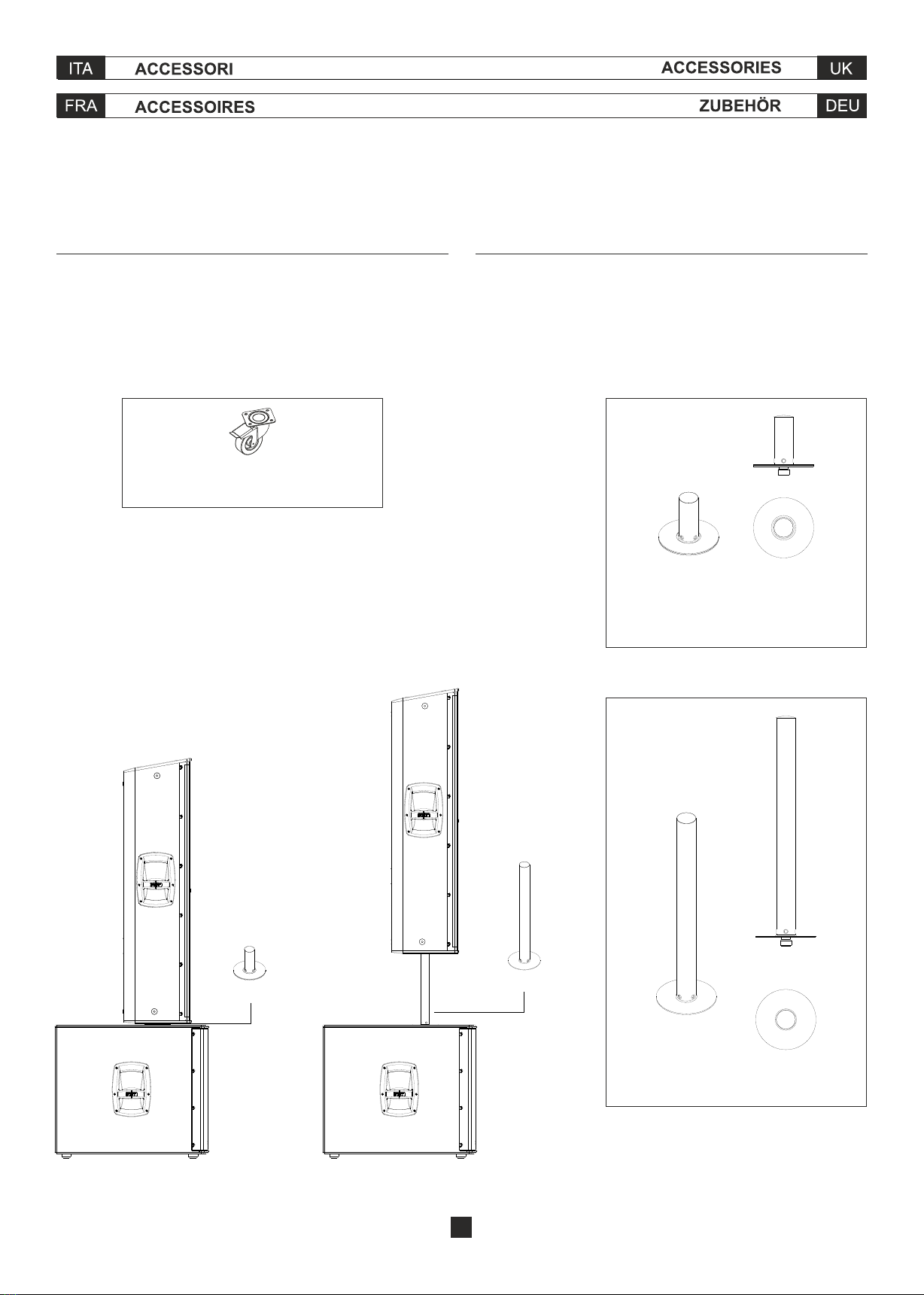
SOLO PER CONFIGURAZIONI A TERRA
ONLY FOR GROUND STACK CONFIGURATION
POUR LA CONFIGURATION AU SOL UNIQUEMENT
NUR FÜR BODENKONFIGURATION
Selezionare con cura l’area dove installare i diffusori e assicurarsi che la
struttura sia adeguata a supportare il peso del box. Posizionare il sistema
su una superficie piana e non sdrucciolevole.
La FBT Elettronica SpA non è responsabile di eventuali danni a persone o
cose in caso di mancato rispetto delle presenti indicazioni o mancata
verifica del fattore di sicurezza.
Carefully select the area where to install the speakers and make sure that
the structure is adequate to support the weight of boxes. When the
subwoofer is installed on the ground, position the system on a flat and non-
slip surface.
FBT will not be held responsible for any damage to persons or property in
case of failure to comply with these instructions or failure to check the safety
factor of all components involved in the installation system.
Choisir soigneusement l’endroit où installer les haut-parleurs et s’assurer
que la structure est suffisante pour supporter le poids des boîtes. Placer le
système sur une surface plane et non glissante.
FBT n’est pas responsable des dommages éventuels aux personnes ou
choses en cas de manque de respect des présentes indications ou non
vérification du facteur de sécurité sur tous les éléments su systàme.
Den Bereich, wo die Lautsprecher zu installieren sind, sorgfältig auswählen
um und sicherstellen, dass die Struktur geeignet ist, um das Gewicht der
Box zu stützen. Im falle der Installation mit Subwoofer auf dem Boden, das
System auf einer flachen und nicht rutschbaren Oberfläche positionieren.
FBT ist nicht verantwortlich für Schäden an Personen oder Sachen im Falle
der Nichtbeachtung dieser Anweisungen oder der nicht erfolgten Prüfung
des Sicherheitsfactors aller an der Aufhängung des Systems beteiligten
Bestandteile.
VT-S 0 406
Speaker stand h 0
VT-S 30 406
Speaker stand h 30cm
KBW-1004S
4 Wheels Kit with brake 100 mm ø
8
VT-S 30 406
VT-S 0 406
Subwoofer Subwoofer
ON
GND
LIFT PHASE
180˚
0˚
+6dB
0
0
0
0
0.5
11.5 22.5
3
3.5
PRESETLEVEL
DELAY
mt.
1
2
3
45
6
7
8
IN LINK
PEAK
OFF
ON
LMT
PRT
VERTUS CLA 118SA
2-Deep
3-Punch
4-DJ
CARDIOID REAR:
5-Original
6-Deep
7-Punch
8-DJ
1-Original
DELAY: controllo di una linea di ritardo digitale che agisce sul segnale di
ingresso; in questo modo è possibile compensare il disallineamento sul
piano verticale di sub e satellite. Il delay è espresso in metri e va da 0.5 a 3.5
metri a passo di 50cm.
LEVEL: regola il livello generale del segnale.
PRESET: seleziona 8 preset ad ognuno dei quali corrisponde una
configurazione di diffusori, in base alle preferenze personali e all'acustica
dell'ambiente di ascolto.
GND LIFT: interruttore per la separazione elettrica tra il circuito di massa e il
circuito di terra, onde evitare possibili "loop" di massa, causa di fastidiosi
ronzii.
ON: indica l'attivazione del sistema.
PHASE: il controllo "fase" consente di ottimizzare l'allineamento di fase,
cioè di ottenere una risposta in frequenza uniforme nella zona di incrocio tra
sub e satellite. Nella posizione "0°" l'emissione sonora del sub è in fase con il
segnale di ingresso; nella posizione "180°" l'emissione sonora è in contro-
fase con il segnale di ingresso; questo controllo consente di ottenere
ulteriore flessibilità nella messa a punto del subwoofer ottimizzandone le
prestazioni.
PEAK: l'accensione del led indica che il livello del segnale è prossimo alla
saturazione.
LMT/PRT: l'accensione del led indica il malfunzionamento del sistema
dovuto ad un guasto dell'amplificatore interno o all'intervento dei circuiti di
limitazione per evitare sovraccarico termico.
IN-LINK: prese di ingresso/uscita bilanciate; "IN" consente il collegamento
di un segnale preamplificato come, ad esempio, quello in uscita da un mixer;
"LINK" permette il collegamento di più diffusori con lo stesso segnale.
DELAY: Control of a digital delay line acting on the input signal; in this way it
is possible to make up for the vertical misalignment of sub and satellite. The
Delay is expressed in metres and goes from 0.5 to 3.5 m with 50cm steps.
LEVEL: It adjusts the signal general level.
PRESET: Selects 8 presets, each of whom corresponds to a specific
speaker configuration according to users' personal preferences and to the
acoustics of the listening area
GND LIFT: A switch for the electric separation between the ground and earth
circuits; this can be useful in order to remove the irritating noises caused by
ground loops.
ON: Indicates that the system is on.
PHASE: The Phase control allows to optimize phase alignment, i.e. to
obtain a uniform frequency response in the crossover area between the sub
and the satellite. When it is set at 0°, the sound emission is in phase with the
input signal; when it is set at 180° the sound emission is in counterphase
with the input signal; thanks to this control, subwoofer adjustment will be
even more flexible with a consequent performance optimization.
PEAK: When this LED lights up, it indicates that the signal is reaching
saturation.
LMT/PRT: If this LED lights up, there is a system malfunction due to an
internal amplifier failure or to the intervention of current limiting circuits
against thermal overload.
IN-LINK: Balanced input/output sockets; “IN” allows to connect a pre-
amplified signal such as that coming, for instance, from mixer output. “LINK”
allows to connect multiple speakers to the same signal.
DELAY: Contrôle d'une ligne de retard numérique qui agit sur le signal
d'entrée ; de cette façon on peut compenser le désalignement sur le plan
vertical du sub et du satellite. Le délai est indiqué en mètres et va de 0,5 à
3,5 mètres à pas de 50cm.
LEVEL: : Il règle le niveau général du signal.
PRESET: Il sélectionne 8 presets, dont chacun correspond à une
configuration de diffuseurs spécifique, selon les préférences personnelles
et l'acoustique de l'environnement d'écoute
GND LIFT: : Interrupteur pour la coupure électrique entre le circuit de masse
et le circuit de terre afin d'éviter de possibles « boucles » de masse, qui
causent des bourdonnements ennuyeux.
ON: : Il indique l'activation du système.
PHASE: Le contrôle Phase permet d'optimiser l'alignement de phase, c'est-
à-dire d'obtenir une réponse en fréquence uniforme dans la zone de
croisement entre sub et satellite. Dans la position 0° l'émission sonore du
sub est en phase avec le signal d'entrée ; dans la position 180° l'émission
sonore est en opposition de phase avec le signal d'entrée ; ce contrôle
permet d'obtenir plus de flexibilité dans la mise au point du subwoofer en
optimisant ses performances.
PEAK: : L'allumage de cette del indique que le niveau du signal est proche
de la saturation.
LMT/PRT: L'allumage de la del indique le mauvais fonctionnement du
système à cause d'une panne de l'amplificateur interne ou de l'intervention
des circuits de limitations pour éviter une surcharge thermique.
IN-LINK: Prises d'entrée/sortie équilibrées ; « IN » permet la connexion d'un
signal pré-amplifié comme par exemple le signal de sortie d'un mélangeur ;
« LINK » permet la connexion de plusieurs diffuseurs avec le même signal.
DELAY: Für die Kontrolle einer digitalen Verzögerungsleitung, die auf das
Eingangssignal wirkt; auf diese Weise ist es möglich, die Sub-Satellite-
Abweichung in der vertikalen Ebene zu kompensieren. Das Delay ist in
Metern angegeben und reicht von 0.5 bis 3.5 Metern in 50 cm-Schritten.
LEVEL: Regelt den allgemeinen Pegel des Signals.
PRESET: : Zur Auswahl der 8 Voreinstellungen, die jeweils einer
Lautsprecherkonfiguration entsprechen, bezüglich der individuellen
Vorlieben und der Akustik des Hörbereichs
GND LIFT: Schalter zur elektrischen Trennung von Masse- und Erdkreis zur
Vermeidung möglicher Masse-LOOPS mit störendem Brummen.
ON: Zeigt die Einschaltung des Systems an.
PHASE: Die Phasenkontrolle erlaubt, die Phasensteuerung zu optimieren,
d.h., eine einheitliche Frequenzantwort im Kreuzungsbereich zwischen Sub
und Satellit zu erhalten. Auf 0°-Stellung findet die Schallemission des
Subwoofers gleichphasig zum Eingangssignal statt; auf 180° findet die
Schallemission gegenphasig zum Eingangssignal statt. Diese Regelung
ermöglicht noch mehr Flexibilität beim Einregulieren des Subwoofers und
somit optimierte Leistungen.
PEAK: Das Aufleuchten dieser Led zeigt an, dass sich der Signalpegel der
Sättigung nähert.
LMT/PRT: Das Aufleuchten dieser Led zeigt eine Fehlfunktion des Systems
an, auf Grund eines Ausfalls des internen Verstärkers oder wegen der
Sicherung, um thermische Überladung zu vermeiden.
IN-LINK: Symmetrierte Ein-/Ausgangsbuchsen; „IN“ ermöglicht den
Anschluss eines vorverstärkten Signals, wie das aus einem Mixer; „LINK“
ermöglicht den Anschluss mehrerer Lautsprecher mit demselben Signal.
9
2-Deep
3-Punch
4-DJ
CARDIOID REAR:
5-Original
6-Deep
7-Punch
8-DJ
1-Original
10
11
11
11
11

con 2 sub;
FRONT
REAR
FRONT
REAR
FRONT FRONT REAR FRONT
11
Preset
CARDIOID REAR
ORIGINAL (5)
Preset
ORIGINAL (1)
CONFIGURAZIONI CARDIOIDI CARDIOID CONFIGURATIONS
CONFIGURATIONS CARDIOÏDES KARDIOIDE KONFIGURATIONEN
LINK
IN
12
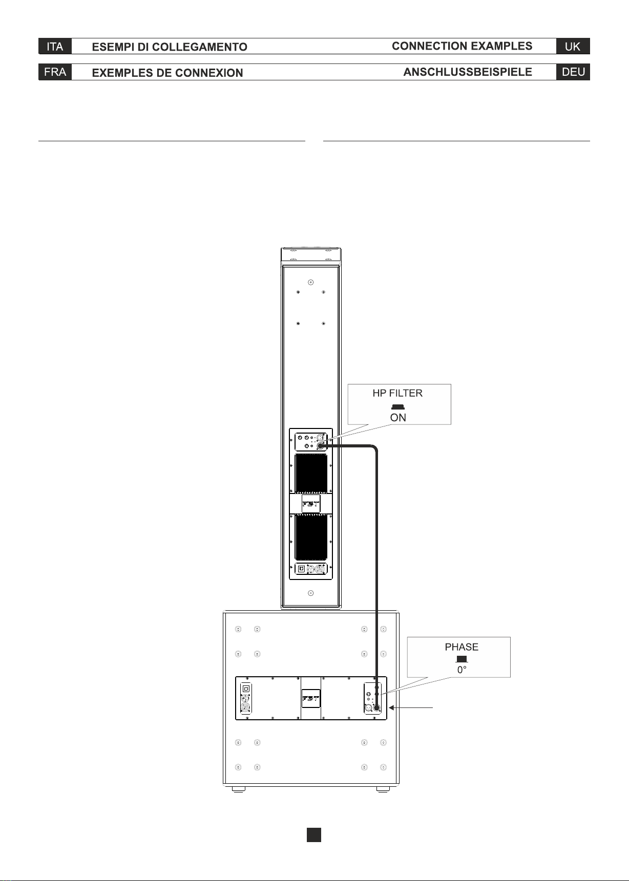
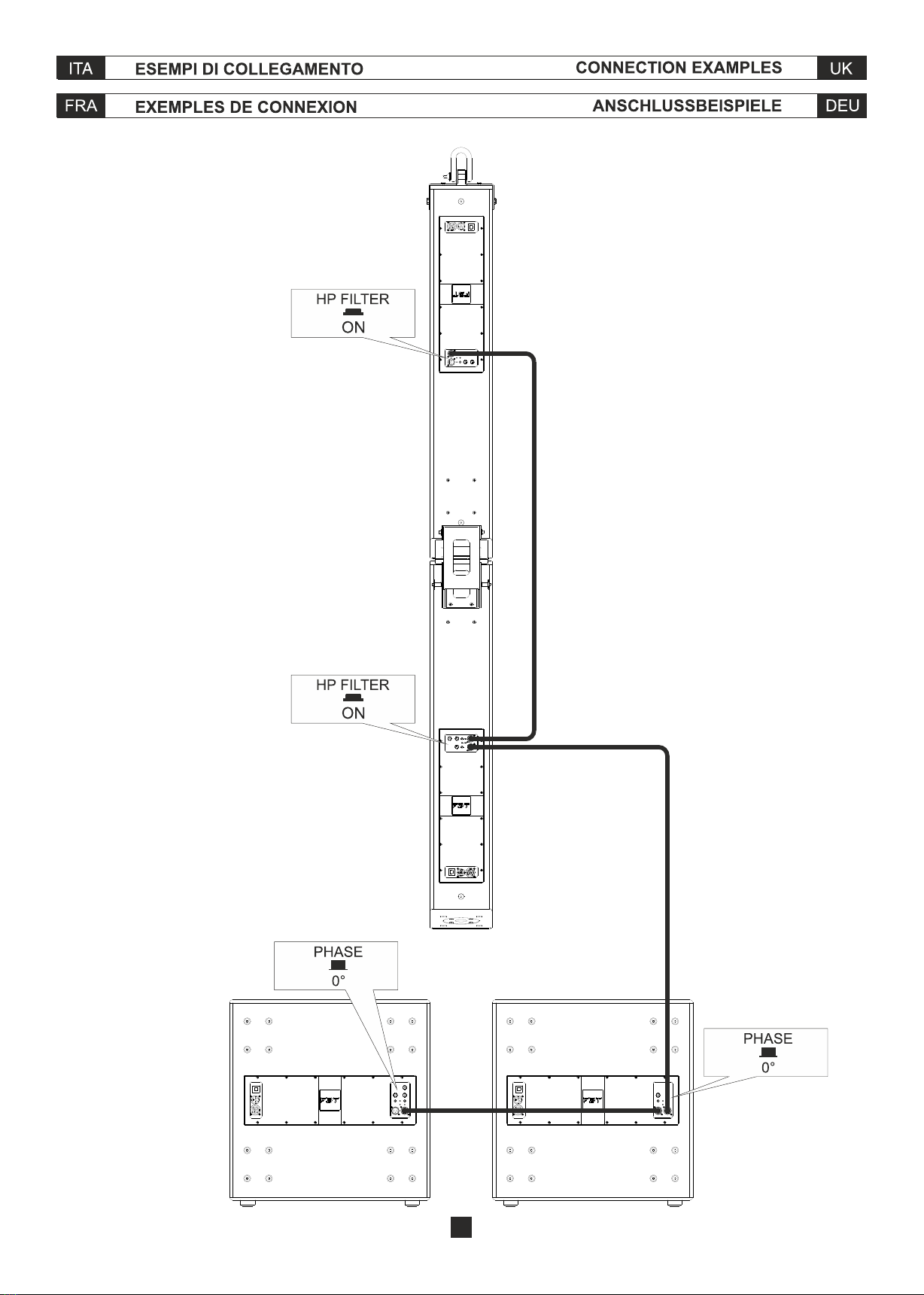
Nella configurazione sub-satellite posizionare il pulsante "PHASE" del sub
nella posizione "0°" e il pulsante "HP FILTER" del satellite nella posizione
"ON".
For sub-satellite configuration set sub "PHASE" switch to "0°" and satellite
"HP FILTER" switch to "ON".
Dans le configuration sub-satellite placer l'interrupteur "PHASE" du sub en
modalité "0°" et l'interrupteur "HP FILTER" du satellite en position "ON".
Bei der Sub-Satellite Konfiguration den Shalter "PHASE" des Subs auf "0°"
und den Shalter "HP FILTER" des Satellits auf "ON" stellen.
CLA 406.2A
CLA 118SA
LINK
IN
IN
LINK
INLINK
13
2 x CLA 406.2A
CLA 118SA CLA 118SA

1200
2400
33Hz - 120Hz
1 reflex
400mm - (18")
bobina/coil/bobine/Spule 75mm (3")
134 / 138
omnidirectional
22
dipendente dal preset
preset dependant
dépend de la preset
von der voreinstellung abhängig
640
XLR con loop
XLR with loop
XLR avec loop
XLR mit loop
5
16,40
555 x 572 x 660
21,85 x 22,51 x 25,98
800 x 755 x 700
31,49 x 29,72 x 27,55
41,5
91,49
51,5
113,53
14


CODE 42144#07.2018
Other Fbt Subwoofer manuals

Fbt
Fbt MODUS SUB Owner's manual

Fbt
Fbt MITUS 118FSA User manual

Fbt
Fbt SUBline 112sa User manual

Fbt
Fbt PSR 118s User manual

Fbt
Fbt HORIZON VHA118SA User manual

Fbt
Fbt MaxX10Sa User manual

Fbt
Fbt SubLine 12SA User manual

Fbt
Fbt PROJECT 1020 SA User manual

Fbt
Fbt Xsub 18 SA User manual

Fbt
Fbt MUSE 118FSND User manual


Popular Subwoofer manuals by other brands


Blaupunkt
Blaupunkt GTr 130 A Operating and installation instructions

Bravox
Bravox UXP10D Installation & operation manual

Monitor Audio
Monitor Audio WS-10 owner's manual

M&K Sound
M&K Sound Professional Powered Subwoofer Operation manual

Sony
Sony XS-L1536 - Subwoofer Parameter guide

Morel
Morel Ultimo Titanium Series installation guide

 owner's manual")


