Fbt PROJECT 1020 SA User manual

ISTRUZIONI PER L’USO
INSTRUCTIONS FOR USE
A C T I V E S U B W O O F E R

Leggere attentamente il presente foglio istruzioni.
FBT Elettronica S.p.A. declina ogni responsabilità per danni a
persone e/o cose derivanti dalla non corretta installazione e dall’uso
improprio del prodotto.
La messa in opera del diffusore deve essere effettuata da
personale addestrato: un’errata installazione potrebbe
comportare il rischio di scossa elettrica.
Please read this instruction sheet carefully.
FBT Elettronica S.p.A. will accept no liability for
personal injury and/or damage to property resulting from
incorrect installation or improper use of the product.
The speaker unit must be set up by trained personnel.
Incorrect installation could result in the risk of electric
shocks.
Avvertenze per lo smaltimento del prodotto ai sensi
della Direttiva Europea 2002/96/EC Alla f ne della sua
vita utile il prodotto non deve essere smaltito insieme
ai rif uti urbani, ma deve essere consegnato presso gli
appositi centri di raccolta differenziata predisposti dalle
amministrazioni comunali, oppure presso i rivenditori
che forniscono questo servizio. Smaltire separatamente un rif uto
elettrico e/o elettronico (RAEE) consente di evitare possibili
conseguenze negative per l’ambiente e per la salute derivanti da
un suo smaltimento inadeguato e permette di recuperare i materiali
di cui è composto al fi ne di ottenere un importante risparmio di
energia e di risorse. Su ciascun prodotto è riportato a questo scopo
il marchio del contenitore di spazzatura barrato.
Important information for correct disposal of the
product in accordance with EC Directive 2002/96/EC
This product must not be disposed of as urban waste at
the end of its working life. It must be taken to a special
waste collection centre licensed by the local authorities
or to a dealer providing this service. Separate disposal
of electric and/or electronic equipment (WEEE) will avoid possible
negative consequences for the environment and for health resulting
from inappropriate disposal, and will enable the constituent materials
to be recovered, with signif cant savings in energy and resources.
As a reminder of the need to dispose of this equipment separately,
the product is marked with a crossed-out wheeled dustbin.
PRECAUTIONS
PRECAUZIONI
ITA EN
PER EVITARE IL RISCHIO DI SHOCK ELETTRICO NON APRIRE IL COPERCHIO
NON USARE UTENSILI MECCANICI ALL’INTERNO CONTATTARE UN CENTRO DI
ASSISTENZA QUALIFICATO. PER EVITARE IL RISCHIO DI INCENDIO O DI SHOCK
ELETTRICO NON ESPORRE L’APPARECCHIATURA ALLA PIOGGIA O ALL’UMIDITA’.
IL DISPOSITIVO DEVE ESSERE COLLEGATO ALLA RETE ELETTRICA PRINCIPALE
ATTRAVERSO UNA PRESA DI ALIMENTAZIONE CON UN COLLEGAMENTO DI MESSA
A TERRA PROTETTIVO.
TO REDUCE THE RISK OF ELECTRIC SHOCKDO NOT REMOVE COVER (OR BACK)
NO USER SERVICEABLE PARTS INSIDEREFER SERVICING TO QUALIFIED SERVICE
PERSONNEL.TO REDUCE THE RISK OF FIRE OR ELECTRIC SHOCKDO NOT EXPOSE
THIS EQUIPMENT TO RAIN OR MOISTURE.
THE DEVICE MUST BE CONNECTED TO THE MAINS THROUGH A POWER OUTLET WITH
A PROTECTIVE EARTH CONNECTION
WARNING
RISK OF ELECTRIC SHOCK
DO NOT OPEN
• This device features a power outlet; install the device so that the outlet for
the power cord is easily accessible.
• For proper air ventilation please make sure to leave sufficient clearance
(min. 11 inch) on all sides of the device.
• Please do not cover the ventilation slots with papers, table cloths, curtains,
etc., in order not to prevent ventilation of the device.
• Please do not place any naked flame source, such as lighted candles, on
the device.
• Please keep the device away from water springs and splashes and please
do not place any objects containing liquids, such as vases, on the device.
• Do not install near any heat sources, such as radiators, heat registers,
stoves or other apparatus (including power amplifiers) that produce heat.
• Do not defeat the safety purpose of the polarized or grounding-type plug.
A polarized plug has two blades with one wider than the other; a grounding
type plug has two blades and a third grounding prong; the wide blade or the
third prong are provided for your safety. If the provided plug does not fit into
your outlet, consult an electrician for replacement of the obsolete outlet.
• Protect the power cord from being walked on or pinched particularly at plugs,
convenience receptacles, and the point where they exit from the apparatus.
• Use only attachments accessories specified by the manufacturer.
• Unplug the apparatus during lightning storms or when unused for long
periods of time.
• For technical assistance, contact qualified personnel.
• Questo dispositivo è dotato di una presa di corrente; installare il dispositivo
in modo che la presa per il cavo di alimentazione sia facilmente accessibile.
• Per una corretta ventilazione, assicurarsi di lasciare uno spazio sufficiente
(min. 11 pollici) su tutti i lati del dispositivo.
• Non coprire le fessure di ventilazione con carta, tovaglie, tende, ecc., in
modo da non impedire la ventilazione del dispositivo.
• Non posizionare sul dispositivo fonti di fiamme libere, come candele accese.
• Tenere il dispositivo lontano da sorgenti d’acqua e schizzi e non posizionare
oggetti contenenti liquidi, come ad esempio vasi, sul dispositivo.
• Non installare vicino a fonti di calore, come radiatori, termoregolatori, stufe
o altri apparecchi (inclusi amplificatori di potenza) che producono calore.
• Non annullare l’obiettivo di sicurezza della spina polarizzata o con messa a
terra. Una spina polarizzata ha due lame, una più larga dell’altra; una spina
con messa a terra ha due lame e un terzo polo di messa a terra; la lama
larga o il terzo polo sono forniti per garantire la propria sicurezza. Se la spina
fornita non si adatta alla presa, consultare un elettricista per la sostituzione
della presa obsoleta.
• Proteggere il cavo di alimentazione in modo da non essere calpestato o
pizzicato in particolare su spine, prese di corrente e il punto in cui escono
dall’apparecchio.
• Utilizzare solo gli accessori specificati dal produttore.
• Scollegare l’apparecchio durante i temporali o se non viene utilizzato per
lunghi periodi di tempo.
• Per assistenza tecnica, contattare il personale qualificato.
ATTENZIONE
RISCHIO DI SHOCK ELETTRICO
NON APRIRE
1
POWER SUPPLY
ALIMENTAZIONE
ITA EN
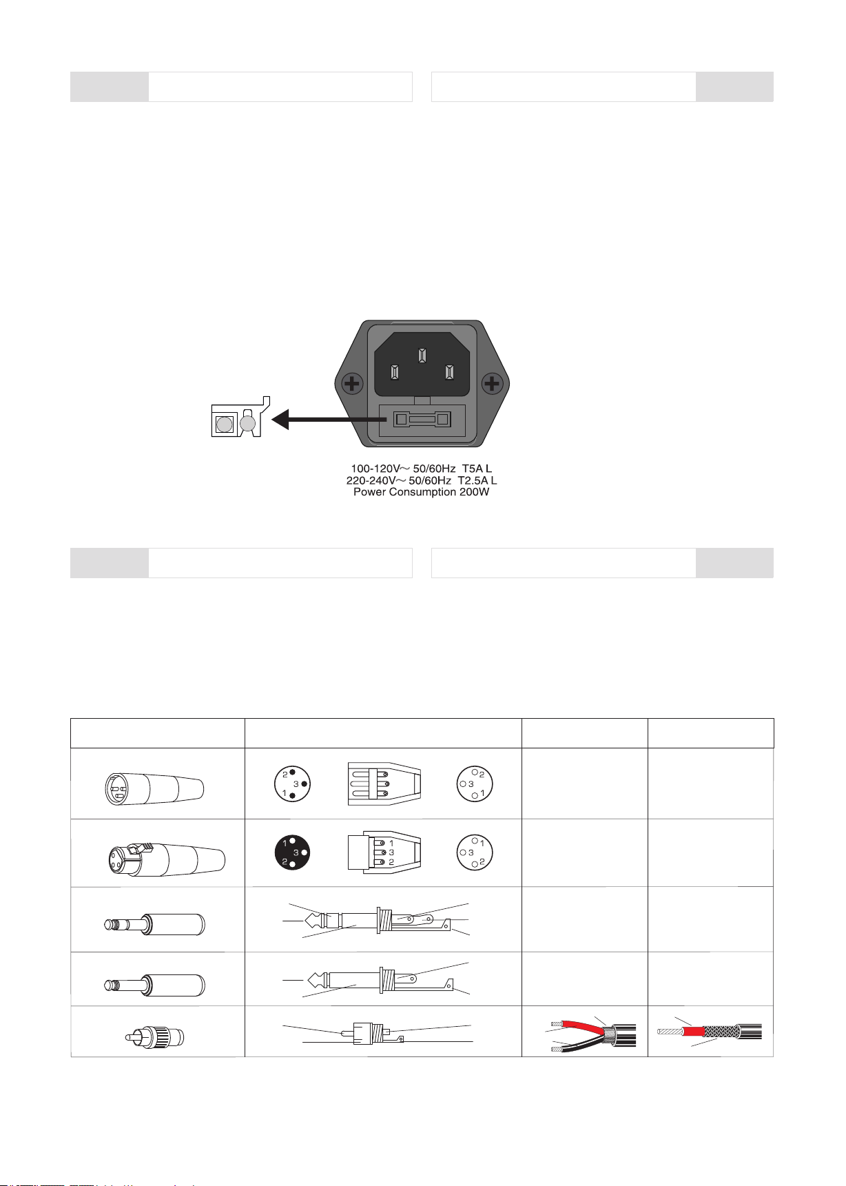
• La presa di alimentazione comprende anche il vano portafusibile.
• Prima di collegare l'apparecchio alla rete elettrica accertarsi che la
tensione di alimentazione corrisponda con quella indicata nel retro
dell'unità.
• I fusibili difettosi devono essere assolutamente sostituiti con altri che
abbiano valore e caratteristiche elettriche uguali.
• Prima di sostituire il fusibile scollegare l'apparecchiatura dalla presa di
alimentazione.
• L'utilizzo di altri tipi di fusibili, soprattutto se di portata maggiore,
potrebbe danneggiare il vostro apparato.
Il diffusore è stato progettato e realizzato per operare con tensione di
rete universale 100-240Vac / 50-60Hz.
• Before connecting the apparatus to the mains make sure the supply
voltage matches the one indicated on the back of the apparatus.
• The power socket also included a fuse box.
• Faulty fuses shall be replaced only with fuses having the same
electrical features and value.
• Before replacing the fuse disconnect the device from the power
socket.
• Different fuses, mainly if featuring higher capacity, could damage the
device.
The speaker has been designed and manufactured to work with 100-
240Vac / 50-60Hz universal mains voltage.
CONNECTION CABLES
CAVI DI COLLEGAMENTO
ITA EN
The system offers numerous, highly flexible possibilities for balanced or
unbalanced connection of professional audio equipment. To avoid
interfering noise, switch off the device or set the output controls to
minimum prior to connecting and disconnecting equipment. Be sure to
use only high-grade cables. The illustrations below show the wiring of
these cables.
Le illustrazioni seguenti mostrano il cablaggio di questi cavi.
Il sistema offre numerose possibilità altamente flessibili per il
collegamento bilanciato o sbilanciato di apparecchiature audio
professionali. Per evitare interferenze spegnere il dispositivo o
impostare i controlli di uscita al minimo prima di collegare e scollegare
l'apparecchiatura. Assicurarsi di utilizzare solo cavi di alta qualità. L
CONNETTORE / CONNECTOR
XLR maschio/male
2 = hot
3 = cold
1 = shield
XLR femmina/female
Jack stereo 6,3mm
Cinch RCA
STRUTTURA / STRUCTURE COLLEGAMENTO BILAN. COLLEGAMENTO SBILAN.
BALANCED CONNECTION UNBALANCED CONNECTION
Jack mono 6,3mm
spina
spina
cavo
cavo
plug
plug
cable
cable
ring
tip
sleeve
tip
ring
sleeve
tip
sleeve
tip
sleeve
tip
sleeve
tip
sleeve
2 = hot
3 = cold
1 = shield
2 = hot
1+3 = shield
2 = hot
1+3 = shield
red = tip
black = ring
shield = sleeve
red = tip
shield = sleeve + ring
red = tip
black = ring
shield = n.c.
red = tip
shield = sleeve
shield
red
black
red
shield
2
FUSE
FUSE
TECHNICAL SPECIFICATIONS
CARATTERISTICHE TECNICHE
ITA EN
Max peak SPL
HF crossover point
LF crossover point
Power output
Type
Inputs
Frequency response
Input impedance
Driver
Impedance
Cabinet
Outputs
Volume
Phase
Features
AC power input
Net weight
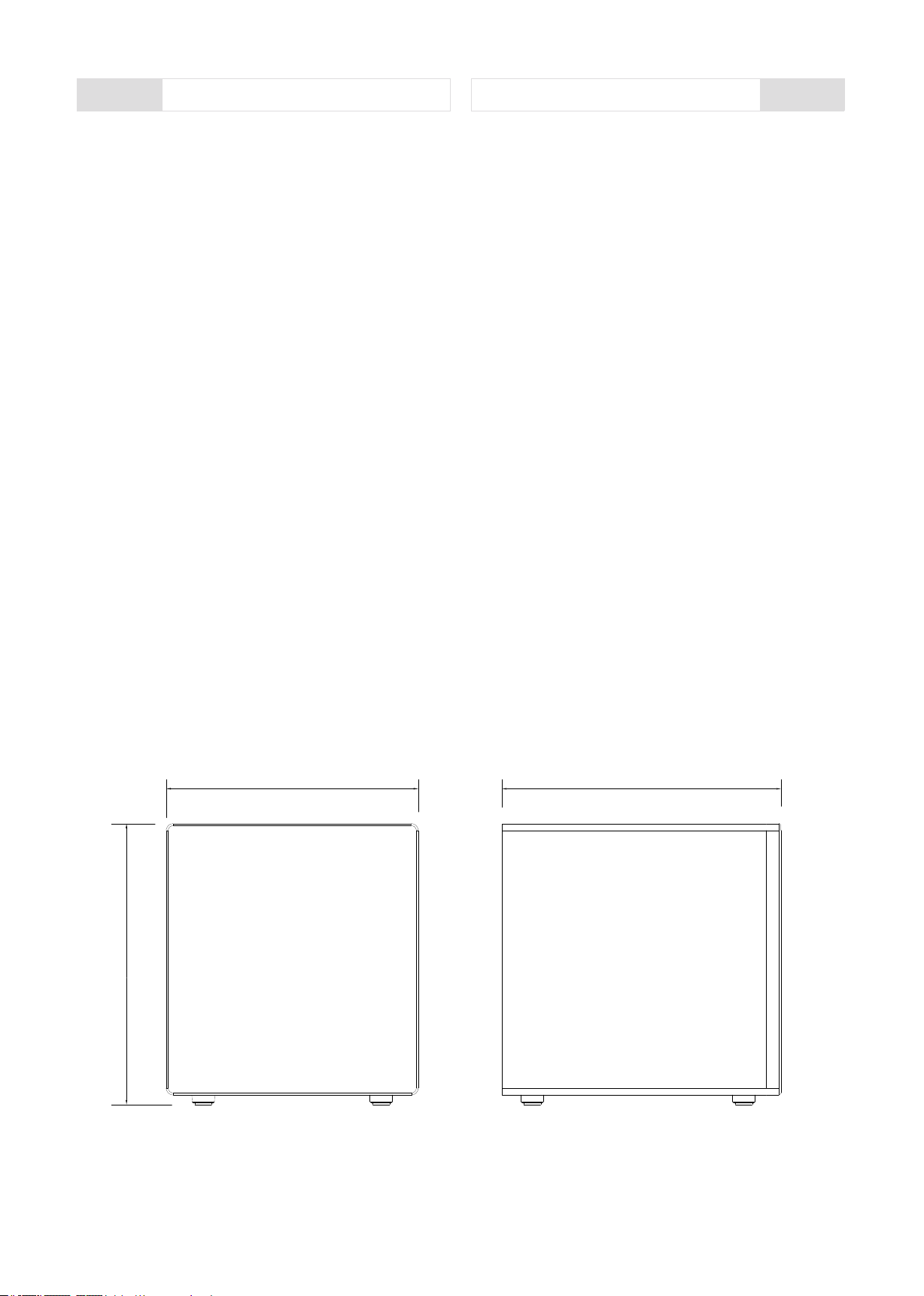
Dimension ( W x H x D )
40 - 150 Hz
4 Ohm
10" active studio monitor subwoofer
110 dB
80 - 150 Hz adjustable
10" subwoofer / pp cone / big-roll edge
Stereo XLR / TRS balanced
Stereo XLR balanced
Class AB design
12,99 x 14,46 x 14,37 in
Normal / Rev switchable
MDF with vinyl finish
Stereo RCA unbalanced
10 kOhm balanced / 20 k unbalanced
Low cut selectable for output
Main volume control
12 dB / oct X-over
Auto-standby
150 W RMS
80 - 120 Hz adjustable
115 V / 230 V~ 50/60 Hz switchable
35,27 lb
Risposta in frequenza
Impedenza
Woofer
Configurazione
Ingressi
Max SPL (peak)
Costruzione
Volume
Impedenza di ingresso
Potenza
HF punto di crossover
Uscite
LF punto di crossover
Caratteristiche
Fase
Dimensioni ( L x A x P )
Alimentazione rete
Peso netto
Auto-standby
Controllo volume generale
12 dB / oct X-over
330 x 367,5 x 365 mm
Design Classe AB
Low cut selezionabile per uscita
Normale / Inversa regolabile
16 kg
80 - 150 Hz regolabile
115 V / 230 V~ 50/60 Hz regolabile
Subwoofer attivo
4 Ohm
40 - 150 Hz
110 dB
10" subwoofer
80 - 120 Hz regolabile
Stereo XLR / TRS bilanciato
MDF con finitura in vinile
Stereo XLR bilanciato
Stereo RCA sbilanciato
150 W RMS
10 kOhm bilanciato / 20 k sbilanciato
3
365mm/14,37"330mm/12,99"
367,5mm/14,46"
FRONT SIDE

CONTROLS AND FUNCTIONS
CONTROLLI E FUNZIONI
ITA EN
4
INPUTS ---------------------------------------------------------------------------------
Ingressi stereo XLR utilizzati per collegare sorgenti audio bilanciate a
livello di linea.
Lo switch PHASE che permette di rovesciare di 180° la fase del segnale
in ingresso; utile per correggere un non perfetto allineamento del sub
rispetto ai satelliti collegati.
AUTO STANDBY attiva la modalità basso consumo in assenza di
segnale in ingresso, dopo un periodo di tempo di inattività di circa 7 min
e il led PWR diventa rosso.
OUTPUTS -----------------------------------------------------------------------------
La sezione MASTER comprende il led PWR di segnalazione di
accensione del sistema.
Il controllo di VOLUME che regola il livello del subwoofer.
La funzione di CROSSOVER che permette di selezionare la frequenza
del filtro Low-pass con un taglio da 80 a 150Hz.
Uscite stereo XLR bilanciate predisposte al collegamento di altri
subwoofer o satelliti adottati dal sistema; solo nel caso di satelliti che
necessitano di filtro hi-pass posizionare lo switch LOW CUT in
posizione ON. Il relativo potenziometro permette di regolare la
frequenza del filtro da 80 a 120Hz.
MASTER -------------------------------------------------------------------------------
LINE: ingressi RCA sbilanciati utilizzati per collegare sorgenti audio
sbilanciate a livello di linea.
In questo modo si eviteranno danni al diffusore stesso ma soprattutto
alle persone che potrebbero trovarsi davanti; si eviteranno anche quei
fastidiosi "bump" causati dall'accensione delle apparecchiature audio a
monte dei diffusori. È buona regola che i diffusori amplificati e gli
amplificatori in genere siano sempre le ultime apparecchiature ad
essere accese e le prime ad essere spente.
Prima di collegare il sistema all'alimentazione di rete e prima di
connettere il segnale, assicurarsi di selezionare la tensione di
alimentazione corrispondente a quella del paese di utilizzo del
dispositivo e che tutti i controlli di volume, sia del subwoofer che delle
sorgenti collegate, siano al minimo; accendere prima la sorgente
sonora e poi il diffusore a lei collegata.
Before connecting the system to the mains power supply and before
connecting the signal, be sure to select the supply voltage
corresponding to that of the country in which the device is used and that
all the volume controls, both of the subwoofer and of the connected
sources, are to a minimum.
Turn on the sound source first and then the speaker connected to it.
In this way you will avoid damage to the speaker itself but above all the
people who might be in front of it; you will also avoid those annoying
"bumps" caused by switching on the audio equipment upstream of the
speakers. It is a good rule that powered speakers and amplifiers in
general are always the last devices to be turned on and the first to be
turned off.
AUTO STANDBY activates the low consumption mode in the absence
of an input signal, after a period of inactivity of about 7 min and the PWR
LED turns red.
The PHASE switch that allows you to reverse the phase of the input
signal by 180 °; useful for correcting an imperfect alignment of the sub
with respect to the connected satellites.
XLR stereo inputs used to connect balanced line level audio sources.
The CROSSOVER function that allows you to select the frequency of
the Low-pass filter with a cut from 80 to 150Hz.
OUTPUTS -----------------------------------------------------------------------------
LINE: Unbalanced RCA inputs used to connect line level unbalanced
audio sources.
The MASTER section includes the PWR led to signal system power on.
MASTER -------------------------------------------------------------------------------
Balanced XLR stereo outputs designed for connection to other
subwoofers or satellites adopted by the system; only in the case of
satellites that require a hi-pass filter, place the LOW CUT switch in the
ON position. The relative potentiometer allows you to adjust the filter
frequency from 80 to 120Hz.
The VOLUME control that adjusts the subwoofer level.
INPUTS ---------------------------------------------------------------------------------

CONNECTION EXAMPLES
ESEMPI DI CONFIGURAZIONI
ITA EN
5
PROJECT SERIES
SIGNAL
CLIP
CLIP
SIGNAL
SUM (60W)
STEREO
THERMAL
EMERG.
CH 1 CH 2 CH 3 CH 4
SIGNAL
CLIP
CLIP
SIGNAL
SUM (60W)
STEREO
THERMAL
EMERG.
CH 1 CH 2 CH 3 CH 4
POWER UNIT
PROJECT SERIES
L
R
POWER UNIT

CONNECTION EXAMPLES
ESEMPI DI CONFIGURAZIONI
ITA EN
6
+
+
+
+
+
+
+
+
+
+
+
+
+
+
+
+
+
+
+
+
+
+
+
+
+
+
+
+
+
+
+
+
+
MIXER
ACTIVE FBT SPEAKERS

Le informazioni contenute in questo manuale sono state scrupolosamente controllate;
tuttavia la FBT non si assume nessuna responsabilità per eventuali inesattezze. La FBT
Elettronica SpA si riserva il diritto di modificare le caratteristiche tecniche ed estetiche dei
prodotti in qualsiasi momento e senza preavviso.
All informations included in this operating manual have been scrupolously controlled;
however FBT is not responsible for eventual mistakes. FBT Elettronica SpA has the right to
amend products and specifications without notice.
CODE: 44281 - 04032021
Table of contents
Other Fbt Subwoofer manuals

Fbt
Fbt XSUB 118 SA User manual

Fbt
Fbt MYRA 218S User manual

Fbt
Fbt MaxX 9Sa User manual

Fbt
Fbt HORIZON VHA 112SND User manual

Fbt
Fbt CLA 118SA User manual

Fbt
Fbt MITUS 118FSA User manual

Fbt
Fbt Xsub 18 SA User manual

Fbt
Fbt MaxX10Sa User manual

Fbt
Fbt SUBline 112sa User manual

Fbt
Fbt JOLLY SUB 10 A User manual


