Vatech Smart Plus PHT-35LHS User manual

Installation manual
Model : PHT-35LHS
Version : 1.29
English


Important Notes
iSmart Plus (PHT-35LHS) Installation Manual
Notice
This manual covers the installation procedures for the Smart Plus (PHT-35LHS)
digital X-ray imaging system. The Installation Manual and the User Manual are
shipped with each hardware unit.
Brand name: Smart Plus (PHT-35LHS)
Manufactured by: VATECH Co., Ltd.
In this manual, “equipment” refers to Smart Plus.
In abbreviated forms, CBCT, CEPH, and PANO denote Cone Beam Computed
Tomography, Cephalo, and Panorama, respectively. They are interchangeably used.
The “Optional” in this manual means that the function or features are left to the
customer’s or user’s choice.
A thorough review of this manual is recommended before installation to ensure the
proper installation of this equipment. The Smart Plus is in steady improvement. The
information contained in this manual may be subject to change without notice,
justification, or notification of the persons concerned.
VATECH Co., Ltd. (manufacturer) reserves intellectual property rights (IPR) for this
manual and the equipment described herein. This IPR is protected by related laws and
reproduction of this manual, in part or in full, is prohibited without the prior written
consent of the Manufacturer.
Windows 10, NVIDIA, etc. are 3rd parties’ prominent or registered trademarks
protected by related laws and these trademarks are used in this manual just only for
explanation.
For further information not covered in this manual or the accompanying
documentation, please contact us:
Telephone: (+82) 1588-9510
E-mail: gcs@vatech.co.kr
Website: http://www.vatech.com
Address: 13, Samsung 1-ro 2-gil, Hwaseong-si, Gyeonggi-do, Korea
Manual Name: Smart Plus (PHT-35LHS) Installation Manual
Version: 1.29
Publication Date: 2021-06

Important Notes
ii Smart Plus (PHT-35LHS) Installation Manual
Important Notes
Moisture could be built upon the equipment from a sudden temperature
change inside and outside the installation room. Allow at least an hour
before turning ON the equipment to avoid condensation.
To avoid improperly balanced equipment, install the device on a flat
surface to maintain stability.
If the equipment is not stable, property damage and personal injury may
occur.
DO NOT push or pull the equipment.
Equipment should only be installed by an authorized technician,
complying with proper installation procedures
Failure to read and understand the information provided in this manual
may result in physical injury, damage to the equipment, or equipment
failure. Please read each CHAPTER in its entirety and understand the
information therein before attempting any of the installation procedures.

Table of Contents
iii Smart Plus (PHT-35LHS) Installation Manual
Table of Contents
Notice ..............................................................................................................................i
Important Notes.............................................................................................................ii
Table of Contents ......................................................................................................... iii
1. Introduction....................................................................................................1
1.1 Manufacturer's Liability ........................................................................1
1.2 Customer’s Responsibility.................................................................... 1
1.3 Conventions in this Manual ..................................................................2
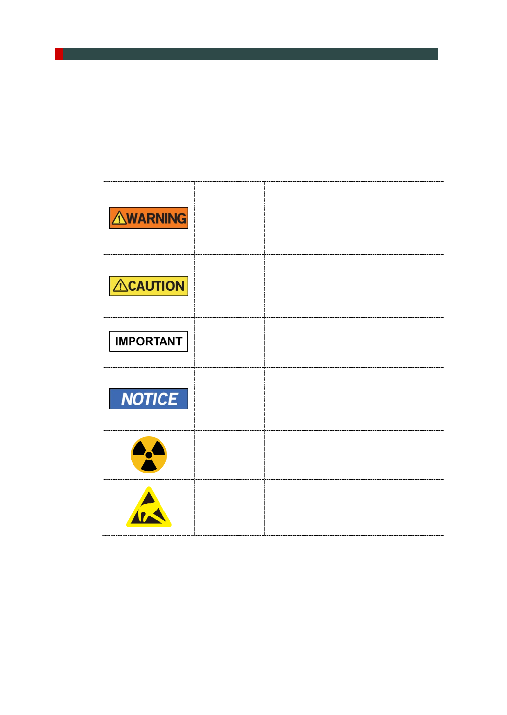
1.4 Marks and Symbols .............................................................................8
1.5 Standards and Regulations................................................................ 10
2. Choosing an Installation Site...................................................................... 11
2.1 Room Requirements .......................................................................... 11
2.2 Specifications for Electrical Installation............................................... 15
2.3 Electrical Requirement....................................................................... 15
2.4Environmental Specifications ............................................................. 17
2.5 Exposure Switch Installation Options ................................................. 18
2.6 Installation Versions ........................................................................... 20
2.7 Installing the Warning Lamp and Door Interlock Switch ...................... 21
2.8 Installing the Emergency Stop Switch ................................................ 21
3. Before Installing the System....................................................................... 22
3.1 Required Tools ................................................................................... 22
3.2 Checking the ShockWatch and TiltWatch Indicators........................... 24
3.3 Unpacking Boxes............................................................................... 25
3.4 Checking the Parts............................................................................. 33
4. Installing the Equipment: Base Stand (Optional)....................................... 40
4.1 Assembling the Base and Main Units................................................. 40
4.2 Installing the CEPH Unit (Optional) .................................................... 44
4.3 Installing the Wall and Column Brackets ............................................ 48
4.4 Fixing the Base (Optional).................................................................. 54
4.5 Connecting the Cables to the Equipment. .......................................... 57
4.6 Removing the Transportation Safety Bolts ......................................... 59
4.7 Leveling the Equipment...................................................................... 61
4.8 Tightening the Bolts ........................................................................... 63
5. Installing the Equipment: Wall Mount......................................................... 64
5.1 Installing the Equipmet....................................................................... 64
5.2 Installing the CEPH Unit (Optional) .................................................... 69
5.3 Installing the Wall and Column Brackets ............................................ 69
5.4 Removing the Transportation Safety Bolts ......................................... 75

Table of Contents
iv Smart Plus (PHT-35LHS) Installation Manual
5.5 Connecting the Cables to the Equipment ...........................................75
5.6 Leveling the Equipment......................................................................76
5.7 Tightening the Bolts............................................................................78
6. Completing Miscellaneous Works ..............................................................79
6.1 Assembling Various Covers................................................................79
6.2 Assembling the Temple Supports and the Chinrest.............................81
6.3 Installing the Switch Holders ..............................................................82
7. Setting up PC ...............................................................................................83
7.1 Direct Connection Diagram ................................................................83
7.2 The Recommended PC Requirements ...............................................84
7.3 Installing the Internal Peripherals .......................................................87
7.4 Connecting the Cables to PC .............................................................89
8. Setting up PC’s Environment Variables......................................................91
8.1 Before Beginning................................................................................91
8.2 Turning the Firewall Off ......................................................................92
8.3 Setting up the Power Mangement Options .........................................93
8.4 Turning off the User Account Control ..................................................95
8.5 Setting Folder Exclusions with Anti-virus Software .............................96
9. Installing Software .......................................................................................97
9.1 Before Beginning................................................................................97
9.2 Software Installation Flow ..................................................................98
9.3 Installing Image Viewer Program........................................................98
9.4 Installing the InstallShield...................................................................99
9.5 Setting up the User-specific Information ........................................... 114
10. Technical Specifications............................................................................137
10.1 Mechanical Specifications. ...............................................................137
10.2 Electrical Specifications....................................................................139
10.3 Environmental Specifications ...........................................................140
Appendix A.................................................................................................................A-1
A. Installing the Warning Lamp and Door Interlock Switch .................... A-1
B. Installing the Emergency Stop Switch............................................... A-4
C. Limiting the Column Height .............................................................. A-5
D. Connecting the 3rd party Exposure Switch (Optional)........................ A-8
E. Checking PC BIOS Settings ............................................................. A-9
F. Installation Checklist ...................................................................... A-10

1. Introduction
Smart Plus (PHT-35LHS) Installation Manual 1
English
1. Introduction
1.1 Manufacturer's Liability
As the manufacturer, VATECH assumes liability for the safe and reliable installation
and operation ofthis equipment only when:
Equipment installation, including software installation, was conducted by an
authorized agent by this installation manual.
The electrical installation was conducted by the appropriate requirements
specified in IEC-60363.
Genuine original or approved replacement parts are used.
Maintenance/repair service has been performed by a qualified technician(s) from
one of our authorized agents.
The equipment has been used under a normal condition by the user's manual.
PC Software has been properly used by the manufacturer’s installation
instructions and user manuals.
1.2 Customer’s Responsibility
Site planning and preparation are the responsibility of the customer. The following
points should be considered fundamentally important to all customers of this product:
Install all required materials before the delivery of the system.
Complete the floor, ceiling, and walls of the room before installing the equipment.
Install proper sized junction boxes, with covers, at the necessary locations.
Install a mains power with the proper voltage output and an adequate kVA rating.
Install the circuit breaker specified by this manual.
Provide the installer(s) with the current dimensions of the room including the
hallway and entry door sizes.
The customer must have an electrician install more than two power outlets in the
room.

1. Introduction
2Smart Plus (PHT-35LHS) Installation Manual
1.3 Conventions in this Manual
The following symbols are used throughout this manual to emphasize information or
indicate potential risks to the equipment or user. Make sure that you fully understand
each symbol and follow the accompanying instructions.
To prevent physical injury and damage to the equipment, please observe all warnings
and safety information included in this document.
WARNING
Indicates that a specific hazard is known to
exist which through inappropriate
conditions or actions may cause:
Severe personal injury (to the
operator and patient)
Substantial property damage.
CAUTION
Indicates that a potential hazard may exist
which through inappropriate conditions or
actions will or can cause:
Minor injury
Property damage.
IMPORTANT
Indicates that a potential problem may
exist which through inappropriate
conditions or actions can cause:
Property damage.
NOTE
Indicates precautions or recommendations
that should be used in the operation of the
system, specifically:
Using this Manual
Notes to emphasize or clarify a point.
RADIATION Indicates a possible danger from radiation
exposure.
ESD
susceptibility
Indicates that an item is susceptible to
damage from electrostatic discharges.

1. Introduction
Smart Plus (PHT-35LHS) Installation Manual 3
English
Never touch or hold the sensor or tube head areas while
moving, installing, or operating the equipment.

1. Introduction
4Smart Plus (PHT-35LHS) Installation Manual
DO NOT step on the base unit while installing or operating
the equipment.
DO NOT use the electric drill for tightening / untightening
screws. Use it only for drilling a hole on the wall.
Grab the recommended holding areas only to transport
the equipment. (See below)
Four installers are required to install the equipment safely.

1. Introduction
Smart Plus (PHT-35LHS) Installation Manual 5
English
Locations of the Emergency Stop Switch and the Main
Power Switch
Make sure to read and fully understand the installation
instructions before installation. The installer must
confirm that the system is installed according to the
instructions provided by this manual and perform the
appropriate procedures therein.
If the equipment has been stored at temperatures of
below 10℃(50℉) for more than a couple of hours,
allow the equipment to reach room temperature before
applying mains voltage.
Installation and related work must only be performed by
people authorized by VATECH.
DO NOT connect any items or equipment to this
system that are not part of the system: IEC60601-1-1
(3rd edition: 2005).
Any equipment not approved by VATECH must comply
with the applicable standards: IEC 60950-1 (2nd
edition: 2005) for IT equipment (Ex: PC) and IEC
60601-1 (3rd edition: 2005) for medical electrical
equipment.
All operators of this equipment are responsible for
ensuring that the requirements outlined in IEC 60601-1-
1 (3rd edition: 2005): Safety Requirements for Medical
Electrical Equipment are fully met to ensure the safety
of patients, operators, and the environment.
Never touch-sensitive areas such as sensors during
installation. These areas are indicated at the
appropriate stages during the installation procedures.
The use of wireless phones may interfere with the
operation of this equipment.
Use an ESD (electrostatic sensitive device) wristband
during installation and connect it to a ground wire.
Touch a ground point to discharge static electricity
before handling PCB boards.
Emergency Stop Switch
Main Power Switch

1. Introduction
6Smart Plus (PHT-35LHS) Installation Manual
Installation Site
The PC Monitor, Emergency Cut Off Switch, and X-ray
Exposure Switch should be installed near the operator
so that he or she can manage them simultaneously in
an emergency.
Proper shielding of the room is essential. The installers
are responsible for verifying that all applicable radiation
safety requirements are met since the requirement
varies depending on the country. Since the requirement
varies depending on the country. It is the installer’s
responsibility to verify that all applicable radiation safety
requirements are met.
DO NOT install the equipment near other devices.
DO NOT install the equipment in an area that is
exposed to strong electromagnetic fields.
DO NOT install the equipment in an area where there is
the risk of an explosion.
The electrical installation of this system shall comply
with all local code requirements for electro-medical
systems: IEC 60364-7-710:2002.
It is strongly recommended that a UPS be installed at
the same time as the equipment.
The equipment, PC, and all peripheral devices must be
well-grounded.
Warnings Regarding X-ray Radiation
Failure to install this equipment in an approved location
may be dangerous to the patient and operator.
Stationary radiation shielding must be installed to
protect the operator from radiation.
The X-ray system may cause injury to the patient if
improperly used. Obey all federal and municipal
standards regarding radiation safety.
When exposing the patient to the X-ray, the operator
must be behind a protective wall or take other
protective actions. The operator should remain at least
2 m (7 feet) away from the X-ray when pressing the
Exposure Switch and observe the patient and capture-
progression.
Operators must provide protective clothing to the
patient before X-ray capturing. Pregnant women must
consult with a doctor before being exposed to an X-ray.

1. Introduction
Smart Plus (PHT-35LHS) Installation Manual 7
English
This equipment complies with the following
standards:
IEC60601-1-1:2005 Standard Safety Requirements for
Medical Electrical Equipment
IEC 60601-1-2:2005 Electromagnetic Interference
IEC 60601-1-3:2005 Radiation Protection
IEC 60601-1:2005 Standards for Medical Electrical
Equipment
IEC 60950-1: 2nd edition:2005 Standards for Information
Technology Equipment
IEC60601-2-7 and IEC60601-2-28: X-ray Tube Heads
IEC60364-7-710: 2002 Local Code Requirements for
Electro-Medical System Installation
IEC 60601-1-1:2005 regulation shall be met to their full
extent for the safety of the patients, operators, and the
environment—when any person assembles or modify a
medical electrical system by combing it with other
equipment.
Any equipment not provided by VATECH can be
connected when the following standards have complied
with IEC 60950-1 and IEC 60601-1
The electrical installation shall comply with local code
requirements for electro-medical systems: IEC 60364-7-
710: 2002.

1. Introduction
8Smart Plus (PHT-35LHS) Installation Manual
1.4 Marks and Symbols
Symbols Description Location
Dangerous voltage
Powerboard/
Inverter
board/Mono
block
Protective earth (Ground) Column
Off (power: disconnected to the
Main Power Switch)
Main Power
Switch
On (power: connected to the Main
Power Switch)
Main Power
Switch
Alternate current Label
Type B Applied Equipment
(IEC 60601-1: Degree of protection
against leakage current and electric
shock: Class 1 equipment)
Label
Radiation hazard Label
Indicates the authorized
representative in the European
Community.
Label
The CE symbol indicates that this
product complies with the
European Directive for Medical
Devices 93/42/EEC as amended by
2007/47/EC as a class IIb device.
Label
UL mark No. E476672 Label
Caution: Federal law restricts this
device to sale by or about a
licensed healthcare practitioner.
Label
Addresses where the equipment
was manufactured. Label

1. Introduction
Smart Plus (PHT-35LHS) Installation Manual 9
English
Symbols Description Location
Indicates that electrical and
electronic equipment must not be
disposed of as unsorted municipal
waste and must be collected
separately.
Label
Warns ESD hazard.
MCU
board/Board
package
Indicates that this equipment is
classified as a CLASS 1 LASER
PRODUCT by IEC 60825-1 ED.2
regulations.
Label
Indicates that the user needs to
refer to the Instruction Manual. Label
Indicates the date when the
equipment was manufactured. Label
Indicates the manufacturer's serial
number so that specific equipment
can be identified.
Label

1. Introduction
10 Smart Plus (PHT-35LHS) Installation Manual
1.5 Standards and Regulations
Standards
Smart Plus is designed and developed to comply with the following international
standards and regulations:
MEDICAL - APPLIED ELECTROMAGNETIC RADIATION EQUIPMENT
AS TO ELECTRICAL SHOCK, FIRE AND MECHANICAL HAZARDS ONLY IN
ACCORDANCE WITH
ANSI/AAMI ES60601-1 (2005) + AMD 1 (2012),
CAN/CSA-C22.2 No. 60601-1 (2014), IEC 60601-1-3 (2008), IEC 60601-2-63
(2012)
21 CFR 1020.30, 31, 33
NEMA Standard publication PS 3.1-3.18
This is Class IIb equipment and obtained CE marking in
April 2007 for regulations compliance in accordance with
the revised European Union’s MDD (Medical Devices
Directive) 93/42 EEC.
This equipment received the UL certification mark in
accordance with ANSI/AAMI, CAN/CSA-C22.2 No.
60601-1 regulations.
Classifications (IEC 60601-1 6.1)
The degree of protection against water ingress: Ordinary Equipment: IPX0
The degree of protection against electric shock: Class 1 equipment, Type B
Applied Parts: Temple Supports, Chinrests, and Bites.

2. Choosing an Installation Site
Smart Plus (PHT-35LHS) Installation Manual 11
English
2. Choosing an Installation Site
2.1 Room Requirements
The location of this equipment should allow for the high
visibility of the patient by the operator, and the operator
should be as about the patient as possible.
This equipment should not be installed on thick carpets
for stability reasons.
Anti-static floor materials should be used around the
equipment.
The PC monitor, emergency cut-off switch, and X-ray
Exposure Switch should be installed near the operator
so that he or she can manage them simultaneously in
case of an emergency.
<Without CEPH Unit (optional): 2,044.3 mm (L) x 2,457.5 mm (W) or wider >

2. Choosing an Installation Site
12 Smart Plus (PHT-35LHS) Installation Manual
<With CEPH Unit (optional): 2805.9 mm (L) x 2,457.5 mm (W) or wider >

2. Choosing an Installation Site
Smart Plus (PHT-35LHS) Installation Manual 13
English
<Ceiling Height: 2,437.5 mm (H) or higher >

2. Choosing an Installation Site
14 Smart Plus (PHT-35LHS) Installation Manual
Minimum Space Required
Without CEPH unit 2,044.3 mm (L) x 2,457.5 mm (W) x 2,437.5 mm (H)
With CEPH unit 2,805.9 mm (L) x 2,457.5 mm (W) x 2,437.5 mm (H)
If the ceiling height is less than 2402 mm (without Base) /
2437.5 mm (with Base) (= max. height of the column + 100
mm), refer to Appendix C. Limiting the Column Height to
lower the max. The height of the column.
Lead Thickness
≥1 mm
The width of the Entrance
The door of the X-ray room should have a clearance of more than 800 mm (31.5”) wide.
Floor Area
The floor of the X-ray room must be stable and level for system balance.
The floor must be able to support a minimum weight of 500 kg/m2(110 lbs. / feet2)
Protection against Radiation
To protect against radiation hazards, follow all federal and municipal requirements.
During exposure, the operator should follow applicable radiation shielding
requirements and remain at least 2m (7’) from the source of the radiation.
Maintain visible contact with the patient and a clear view of indicators such as the
warning lamp and imaging status on the PC.
Other manuals for Smart Plus PHT-35LHS
1
Table of contents
Other Vatech Diagnostic Equipment manuals
Popular Diagnostic Equipment manuals by other brands

Hella Gutmann
Hella Gutmann mega macs PC Bike quick start guide

YIC Technologies
YIC Technologies EMScannerR Setup guide

X-tra Seal
X-tra Seal Smart Sensor ELITE quick start guide

Renishaw
Renishaw Equator installation guide

Diagnostic Associates
Diagnostic Associates DA-ST512 user manual

Dinan
Dinan Dinantronics X user manual