6
Installation and Maintenance Instructions
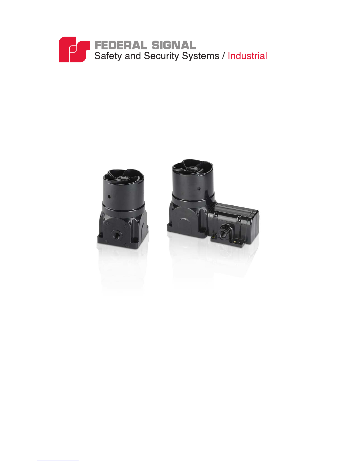
Model G-SND Global Series Sounder
• Establish a procedure to routinely check the sounder system for proper
activation and operation.
• This equipment is suitable for use in Class I, Division 2, Groups A, B,
C, D; Class II, Division 2, Groups F and G; Class III or non-hazardous
locations only.
• WARNING: EXPLOSION HAZARD — Do not disconnect the
equipment unless power has been switched off or unless the area is
known to be non-hazardous.
• WARNING: EXPLOSION HAZARD — Do not remove or replace the
fuse when energized.
Failure to follow all safety precautions and instructions may result in
property damage, serious injury, or death.
With respect to the potential electrostatic charging hazard as mentioned
in the certicate “Specic Conditions of Use”, under normal conditions
of use, these devices are for xed installations and not generally
in contact with people. The risk of ignition is low. In addition,
maintenance, cleaning, and extreme environmental factors (ex. high
velocity dust laden atmospheres or high pressure steam) should be taken
into account by the end user, using local Explosive Atmosphere (Ex)
Electrical installations design, selection, inspection, and maintenance
Codes and Standards. Cleaning of the devices should only be done with
a damp cloth.
Certication
Certicate Nos.: ATEX Cert No.: Baseefa15ATEX0155X
IECEx Cert No.: IECEx BAS 15.0104X
ATEX coding: II 2 G D
Protection: Ex db IIB T5 Gb or Ex db e IIB T5 Gb
Ex tb IIIC T100°C Db IP66 (Tamb= -55°C to + 49°C)
Ex db IIC T4 Gb or Ex db e IIC T4 Gb
Ex tb IIIC T135°C Db IP66 (Tamb= -55°C to + 70°C)
Standards: EN60079-0: 2012 +A11:2013, EN60079-1: 2014,
EN60079-7: 2007, EN60079-31: 2014, IEC60079-0: 6th Ed.,
IEC 60079-1:7th Ed., IEC 60079-7: 4th Ed.,
IEC 60079-31:2nd Ed.