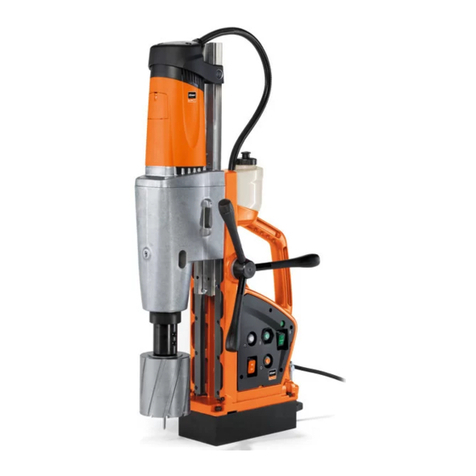
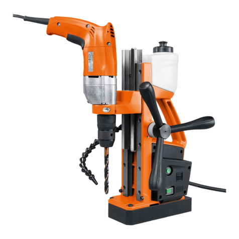
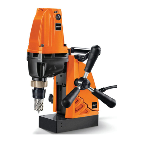
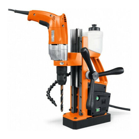
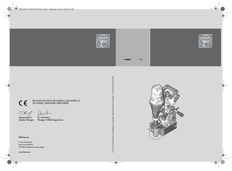
Fein KBM 50 Q User manual

MVK 03 / 07
Alle Rechte bei FEIN, insbesondere für den Fall der Schutzrechtsanmeldung.
Jede Verfügungsbefugnis wie Kopieren und Weitergaberecht liegt bei FEIN.
Fein Repair Tool
Table of Contents
1. Technical Data
2. Maintenance
3. Electrical Functional Testing
4. Disassembly of the Core Drill Unit
5. Assembly of the Core Drill Unit
6. Tools

MVK 03 / 07
Alle Rechte bei FEIN, insbesondere für den Fall der Schutzrechtsanmeldung.
Jede Verfügungsbefugnis wie Kopieren und Weitergaberecht liegt bei FEIN.
Fein Repair Tool
0. Productinformation
Based on some breakdowns on gear housings in the past, stripped thread on the
clamping lever , we mounting a Helicoil –insert in the gear box serially since
Mai 2010. ( siehe picture )

MVK 03 / 07
Alle Rechte bei FEIN, insbesondere für den Fall der Schutzrechtsanmeldung.
Jede Verfügungsbefugnis wie Kopieren und Weitergaberecht liegt bei FEIN.
Fein Repair Tool
1. Technical Data
Order Reference 7 270 30 00 23 4
Type KBM 50 Q
Input Watts 1200
Output Watts 680
Speed, full load R.P.M. 260/520/min
Current type 1~
Protection class l
Cable length with plug m 4
Net weight kg 12
Capacity in steel max. Ø, core drill mm 12-50
Capacity in steel max. Ø, spiral drill (with drill chuck) mm 16
Threaded drill M 16
Tool holder on drill shaft Quick IN
Magnetic holding power N 11000
Drilling depth max. with core drill mm 50
Height (drill jigs) mm 368
Stroke (adjustable) mm 135-310
Magnetic foot dimension mm 180 90

MVK 03 / 07
Alle Rechte bei FEIN, insbesondere für den Fall der Schutzrechtsanmeldung.
Jede Verfügungsbefugnis wie Kopieren und Weitergaberecht liegt bei FEIN.
Fein Repair Tool
2. Maintenance
Please make sure that electric tools are repaired, serviced and tested by
specialists only as repairs carried out in an inexpert manner may cause
considerable hazards for the user (BGV A2).
Repeated tests are to be performed in accordance with DIN VDE 0702-1.
The regulations in accordance with DIN VDE 0701 Part 1 are to be observed after
any repairs.
Withstand voltage at 1000 V (Protection class 1)
Use original FEIN spare parts only!
During commissioning, while working and during maintenance of the core drilling
unit, applicable national accident prevention requirements of the professional
organization must be observed.
The law governing technical working equipment (Device Safety Law) applies in
terms of proper use.

MVK 03 / 07
Alle Rechte bei FEIN, insbesondere für den Fall der Schutzrechtsanmeldung.
Jede Verfügungsbefugnis wie Kopieren und Weitergaberecht liegt bei FEIN.
Fein Repair Tool
2.1. General Maintenance Tasks
Check the power cord (900) for areas of damage.
Blow out the motor with dry compressed air.
Check the carbon brushes (2.2.).
Small functional test (3.1.).
2.1.1. Maintenance intervals:
Depending on the nature and duration of use, no later than after 6 months:
- Clean the drill motor.
- Brush or blow out the brush holder and insulating parts.
2.2. Replacing the carbon brushes:
The drill motor is equipped with carbon brushes that shut off automatically.After the
minimum length of the carbon brushes has been reached, the power supply is
interrupted. If this happens, the carbon brushes must be replaced by an electrical
specialist. If you are using new carbon brushes, make certain to check that they move
easily inside the brush holder.Allow new carbon brushes to run for 15 minutes without
load. Use only
original FEIN carbon brushes!
MVK 03 / 07
Alle Rechte bei FEIN, insbesondere für den Fall der Schutzrechtsanmeldung.
Jede Verfügungsbefugnis wie Kopieren und Weitergaberecht liegt bei FEIN.
Fein Repair Tool
3. Electrical / Functional Tests
3.1. Minor functional test
3.2. Major functional test
3.3. Test data
3.4. Test devices and auxiliary materials
3.5. Wiring diagram
3.6. Safety test
3.7. Functional test

MVK 03 / 07
Alle Rechte bei FEIN, insbesondere für den Fall der Schutzrechtsanmeldung.
Jede Verfügungsbefugnis wie Kopieren und Weitergaberecht liegt bei FEIN.
Fein Repair Tool
3.1. Minor functional test
3.1.1. Self-start lock and magnetic foot
Turn on the master switch and the motor switch. Then connect the core drilling
machine to the electrical power.
The motor must not start up.
The magnetic foot is energized.
Check the power consumption (0.4 A, see 3.3. Test data).
Motor switch off.
Magnetic foot remains energized.
Power consumption must be reduced to one half (0.2 A, see 3.3. Test data).
3.1.2. Motor
Motor switch on.
Motor starts up.
3.1.3. Characteristic curve of the motor
Place the motor under load.
Speed is regulated.
From about 1600 Watts on the speed drops off more sharply.
3.1.4. Overload switch off
Place the motor under heavy load.
The motor switches off after 10 seconds.
The motor must be run at idle for about 60 seconds before the test.

MVK 03 / 07
Alle Rechte bei FEIN, insbesondere für den Fall der Schutzrechtsanmeldung.
Jede Verfügungsbefugnis wie Kopieren und Weitergaberecht liegt bei FEIN.
Fein Repair Tool
Possible causes Test possibilities
Magnetic foot does not
energize:
Check with
magnetisable part
power cable disconnected,
switch off,
connector not plugged in
LED on board must light up
briefly while switching on.
check power voltage on
X1, X2 continuity
magnetic foot defective
LED on board is flashing
measure resistance (504Ω±5%)
elektronics defective
LED on board is flashing
measure voltage on X7.1 and
X7.2 .
Magnetic holding force
too weak: do not turn on while testing
motor switch
measure the voltage on X7.1
and X7.2
measure the magnetic foot defective
measure resistance (504Ω±5%)
removal force
required standing surface uneven
visual inspection
elektronics defective
measure the voltage on X7.1
and X7.2
3.2.1. Major functional test
Note: If the magnetic foot is defective, no further tests are possible.
Because of magnetic foot monitoring, the motor cannot be turned on.
Connect the spare magnetic foot.

MVK 03 / 07
Alle Rechte bei FEIN, insbesondere für den Fall der Schutzrechtsanmeldung.
Jede Verfügungsbefugnis wie Kopieren und Weitergaberecht liegt bei FEIN.
Fein Repair Tool
3.2.2. Major functional test
Possible causes Test possibilities
Motor does not start up:
Switching sequence not
maintained
Turn master switch on first, then
motor switch
Power cord disconnected,
switch off, connector not
plugged in
LED on board must light up
briefly while turning on.
Test mains voltage on X1, X2
Test continuity
Magnetic foot defective
LED on board flashes
Measure resistance (504 Ω
±5%)
Error in motor power supply
line
Test continuity
Motor switch defective
Test
Carbon brushes worn out
Visual inspection
Motor defective
Test motor without electronics
(at max 145 V AC, see 3.3)
Measure idle speed
The reasons listed here
all cause the automatic
startup disable to
engage
Electronics defective
If motor is defective, connect
replacement motor to X5, X6
and connect cable from speed
recorder to X8. Measure idle
speed or voltage

MVK 03 / 07
Alle Rechte bei FEIN, insbesondere für den Fall der Schutzrechtsanmeldung.
Jede Verfügungsbefugnis wie Kopieren und Weitergaberecht liegt bei FEIN.
Fein Repair Tool
3.2.3. Major functional test
Possible causes Test possibilities
Motor only starts up briefly
(1s): Speed cable defective,
intermittent contact
Check continuity, connection
contact
Assembled ring magnet
Visual inspection (loop tracks)
Assembled speed recorder,
speed recorder defective
Connect replacement speed
recorder
Motor switches off for no
apparent reason: Intermittent contact on the
power cord, switch, plug
connections
LED on board must light up
briefly while turning on.
Check continuity on X1, X2
Magnetic foot
LED on board flashes
Measure resistance (504 Ω
±5%)
Electronics
LED on board flashes
Measure voltage on X7.1 and
X7.2.
The reasons listed here all result in the automatic startup
disable being activated

MVK 03 / 07
Alle Rechte bei FEIN, insbesondere für den Fall der Schutzrechtsanmeldung.
Jede Verfügungsbefugnis wie Kopieren und Weitergaberecht liegt bei FEIN.
Fein Repair Tool
3.2.4. Major functional test
Possible causes Test possibilities
No discernable control
behavior:
Check idle speed
Electronics defective
Characteristic curve of motor
Place motor under load.
Speed is regulated.
From about 1600 Watts on the
speed drops off more sharply.
Speed too high or too low;
speed fluctuates: Motor defective
Test motor without electronics
(at max 145 V AC, see 3.3)
Measure the idle speed
Check idle speed Ring magnet defective
Visual inspection (loop tracks)
Electronics defective
If motor is defective, connect
replacement motor to X5,X6
and connect cable from speed
recorder to X8. Measure idle
speed or voltage.
Additional mechanical load
(gears, bearing, vibrations,
etc.)
Test
Measure idle current
Commutator or carbon
brushes defective
Visual inspection for brush
sparking

MVK 03 / 07
Alle Rechte bei FEIN, insbesondere für den Fall der Schutzrechtsanmeldung.
Jede Verfügungsbefugnis wie Kopieren und Weitergaberecht liegt bei FEIN.
Fein Repair Tool
3.2.5. Major functional test
Possible causes Test possibilities
Overload switch-off too
early, too late or no switch-
off
Electronics defective
Measure time
Activate overload switch-off.
Heavier load will switch motor
off after 10 seconds.
Motor starts up even though:
- motor switch was activated
before master switch Electronics defective
Check again after replacing
electronics
- power supply line was
plugged in while switches
were closed
Electronics defective
Check again after replacing
electronics
- magnet is defective or not
connected to the electronics Electronics + magnetic foot
defective
Check again after replacing
electronics / check magnetic
foot
- power cord was plugged in
with damaged master switch
and motor switch
Electronics defective
Check again after replacing
electronics

MVK 03 / 07
Alle Rechte bei FEIN, insbesondere für den Fall der Schutzrechtsanmeldung.
Jede Verfügungsbefugnis wie Kopieren und Weitergaberecht liegt bei FEIN.
Fein Repair Tool
Rated voltage 220 –240 V
Test voltage / "10% 230 V
Idle current / "10% 1)
(2.25-2.88 A) 2.5 A
Idle speed / "3% (504-536/min) 520/min
Main switch on
Voltage on: X7.1, X7.2 "10% 3) 100 V DC
Motor switch on, master switch on, self-start lock active
Voltage an: X7.1, X7.2 "10 % 3)
200 V DC
Min. removal force: magnet new / used 4500N/4050 N
Master switch on
Current consumption of magnetic foot "10% 4)
at 25°C
0.2 A
Motor switch on, master switch on, self-start lock active
Current consumption of magnetic foot 4)
10%
"at 25°C 0.4 A
Resistance of magnetic foot "5% at 25°C 504 Ohm
Test voltage of motor without electronics 145 VAC
3.3. Test data
1) Motor current + magnetic flux current. Idle may be significantly less for machines that are well worked in.
2) Measurement on ground steel plate (St37/500 250 25 mm). Activate motor switch first, then master switch.
The drill shaft of the drill motor is pressed against the dynamometer by means of a slewing ring.
3) Nominal voltage, DC.
4) Measured on the power supply line and KBM 50 Q standing on a ground steel plate (St37/500 250 25 mm).

MVK 03 / 07
Alle Rechte bei FEIN, insbesondere für den Fall der Schutzrechtsanmeldung.
Jede Verfügungsbefugnis wie Kopieren und Weitergaberecht liegt bei FEIN.
Fein Repair Tool
3.4. Test devices and auxiliary materials
Multimeter for effective value measurement (voltage, current, resistance).
Speed measuring device
Dynamometer for measuring pressing forces up to about 5000 N.
Ground steel plate, for example ST 37
(dimensions in mm: ca.. 500x250x25)
Isolating transformer, adjustable
(for testing the motor without electronics at 145 V AC)

MVK 03 / 07
Alle Rechte bei FEIN, insbesondere für den Fall der Schutzrechtsanmeldung.
Jede Verfügungsbefugnis wie Kopieren und Weitergaberecht liegt bei FEIN.
Fein Repair Tool
3.6. Safety test (immediately after about 15 min. runup)
Test steps Test type
1. Removal force 1. Place KBM on ground steel plate (St 37) .
2. Plug the power cord into the power socket.
3. Turn the motor switch on; only after that turn the master switch on
4. Measure the removal force, min 4500N (new) or min 4050N (used)
with dynamometer
2 Restart disable 1. Connect the KBM 50Q to 230 V/50 Hz
2. Master switch and motor switch “ON“
3. If the machine starts up, disconnect the power cord
4. Connect the power plug to the electrical power again
= machine must not start up
3. Protective ground
line test 1. Disconnect
Measurement points: gear head against PE on plug
Idle voltage on the measurement device: 4 V-24 V, AC or DC
Measurement current: min. 0.2 A
Test time: 3 sec
PE resistance: max 0.3 Ohm with power cord 4m long
4. Isolation test 1. Disconnect
2. Connect L1 and N
3. Master switch and motor switch “ON“
Measurement points: gear head and screws (270) against L1/N
Test time: 3 sec
Test voltage: 500 V DC
Isolation resistance: min. 2.0M Ohm
5. High-voltage test 1. Disconnect
2. Connect L1 and N
3. Master switch and motor switch “ON“
Measurement points: gear head and screws (270) against L1/N
Test time: 3 sec
Test voltage: 1000 V AC
Triggering current: 5 mA
Please
note!
The require-
ments of DIN
VDE 0701 Part
1 (Appendix
“E” for electr.
tools), current
version, are
definitive for
the safety
test.

MVK 03 / 07
Alle Rechte bei FEIN, insbesondere für den Fall der Schutzrechtsanmeldung.
Jede Verfügungsbefugnis wie Kopieren und Weitergaberecht liegt bei FEIN.
Fein Repair Tool
3.7. Functional test
1. Set both switches to the “0” position.
2. Connect KBM 50 Q to the power supply (230 V/50 Hz).
Turn on the master switch and motor switch.
3. Idle current test: min. 2.25 A
max. 2.88 A
4. Idle test measured on the drill shaft:
Run up time: min. 10 sec
Test time: min. 3 sec
Speed: min. 504 rpm - gear level 2
max. 536 rpm - gear level 2

MVK 03 / 07
Alle Rechte bei FEIN, insbesondere für den Fall der Schutzrechtsanmeldung.
Jede Verfügungsbefugnis wie Kopieren und Weitergaberecht liegt bei FEIN.
Fein Repair Tool
4. Disassembly of the Core Drill Unit
4.1. Preparation
4.2. Drill motor - loosen the drill rig
4.3. Drill motor - gear
4.4. Motor housing
4.5. Drill rig

MVK 03 / 07
Alle Rechte bei FEIN, insbesondere für den Fall der Schutzrechtsanmeldung.
Jede Verfügungsbefugnis wie Kopieren und Weitergaberecht liegt bei FEIN.
Fein Repair Tool
4.0. Preparation
1. Disconnect >>> pull the plug <<<
2. Set switch to “OFF” position
3. Remove accessory clamped in place.
3.
2.
1.
Other manuals for KBM 50 Q
3
This manual suits for next models
1
Table of contents
Other Fein Drill manuals

Fein
Fein DS 648 User manual

Fein
Fein KBM 65 U User manual

Fein
Fein Slugger JMU 404 M User manual

Fein
Fein KBE30 User manual

Fein
Fein DSc 636 User manual

Fein
Fein HandyMaster ABS 9V User manual

Fein
Fein DSk 672 User manual

Fein
Fein KBM 50 Q User manual

Fein
Fein ASzx 736 User manual

Fein
Fein WBP10 Series Setup guide