manuals.online logo
Brands
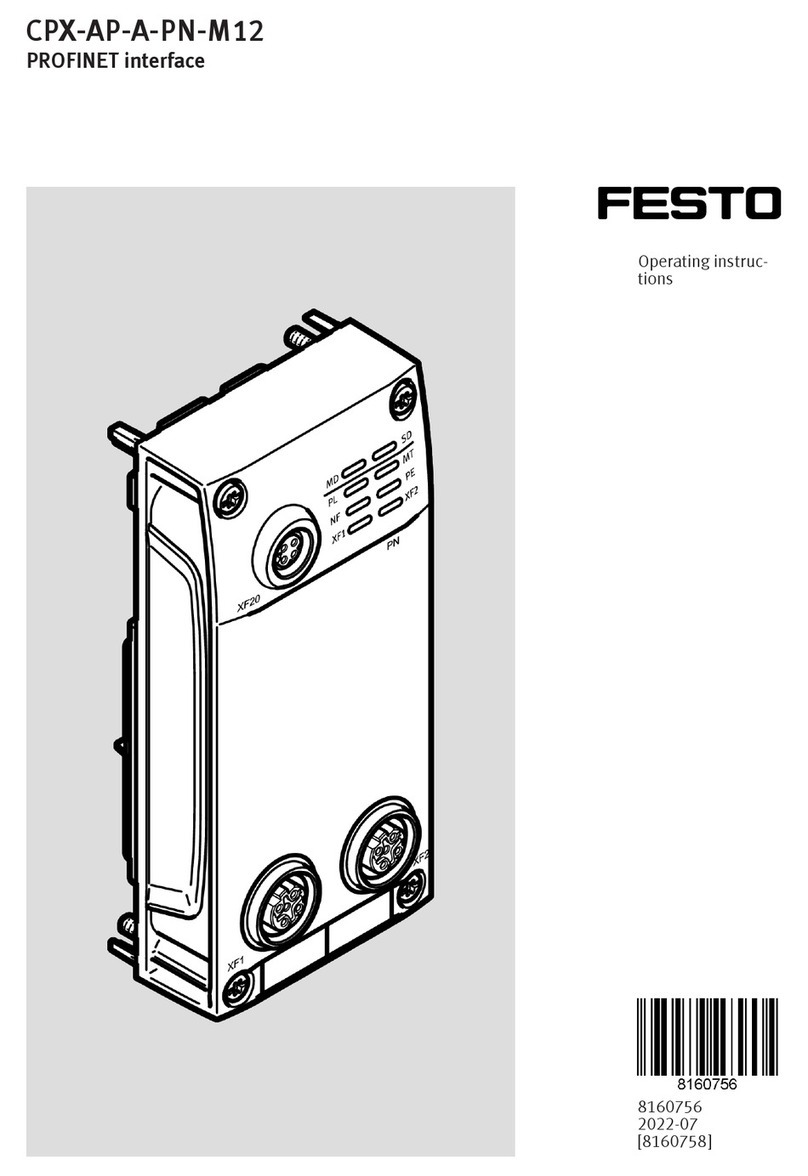
  1. Home
  2. •
  3. Brands
  4. •
  5. Festo
  6. •
  7. Recording Equipment
  8. •
  9. Festo CPX-AP-A-EP-M12 User manual

Festo CPX-AP-A-EP-M12 User manual

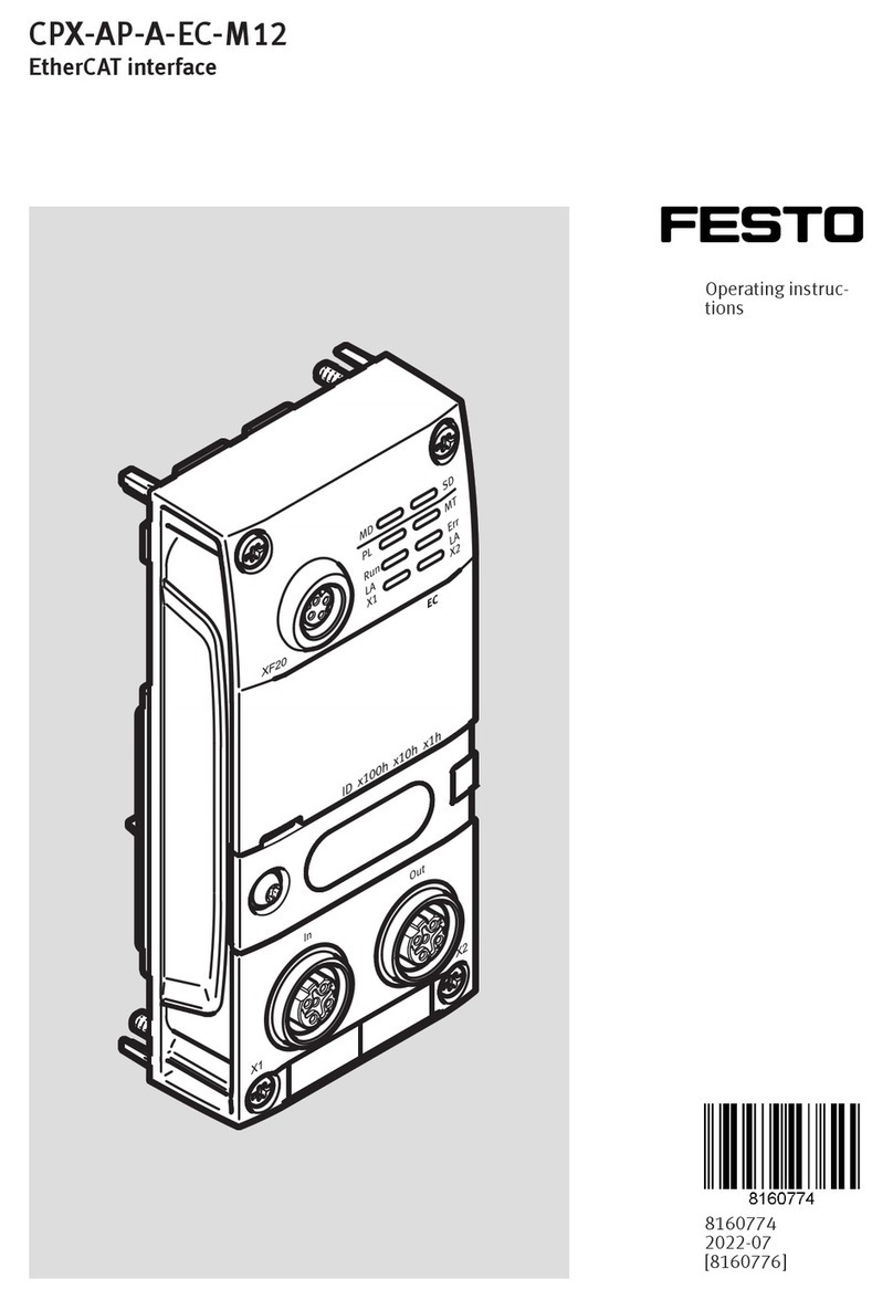
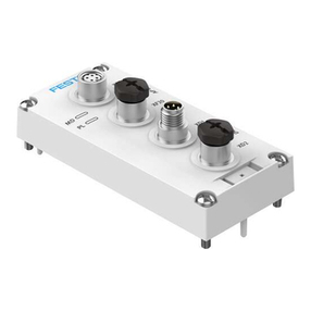
CPX-AP-A-EP-M12
EtherNet/IP interface
Operating instruc-
tions
8160783
2022-07
[8160785]
Translation of the original instructions
EtherNet/IP®, MODBUS®, ROCKWELL AUTOMATION® are registered trademarks of the respective
trademark owners in certain countries.
Festo — CPX-AP-A-EP-M12 — 2022-07
3
Table of contents
1 About this document. . . . . . . . . . . . . . . . . . . . . . . . . . . . . . . . . . . . . . . . . . . . . . . . . . . . . . . . . . . . . 5
1.1 Applicable documents. . . . . . . . . . . . . . . . . . . . . . . . . . . . . . . . . . . . . . . . . . . . . . . . . . . . . . . 5
1.2 Product version. . . . . . . . . . . . . . . . . . . . . . . . . . . . . . . . . . . . . . . . . . . . . . . . . . . . . . . . . . . . 5
1.3 Product labelling. . . . . . . . . . . . . . . . . . . . . . . . . . . . . . . . . . . . . . . . . . . . . . . . . . . . . . . . . . . 5
1.4 Specified standards. . . . . . . . . . . . . . . . . . . . . . . . . . . . . . . . . . . . . . . . . . . . . . . . . . . . . . . . . 5
2Safety. . . . . . . . . . . . . . . . . . . . . . . . . . . . . . . . . . . . . . . . . . . . . . . . . . . . . . . . . . . . . . . . . . . . . . . . . . 6
2.1 Safety instructions. . . . . . . . . . . . . . . . . . . . . . . . . . . . . . . . . . . . . . . . . . . . . . . . . . . . . . . . . . 6
2.2 Intended use. . . . . . . . . . . . . . . . . . . . . . . . . . . . . . . . . . . . . . . . . . . . . . . . . . . . . . . . . . . . . . 6
2.3 Training of qualified personnel. . . . . . . . . . . . . . . . . . . . . . . . . . . . . . . . . . . . . . . . . . . . . . . . 6
3 Additional information. . . . . . . . . . . . . . . . . . . . . . . . . . . . . . . . . . . . . . . . . . . . . . . . . . . . . . . . . . . . 6
4 Product overview. . . . . . . . . . . . . . . . . . . . . . . . . . . . . . . . . . . . . . . . . . . . . . . . . . . . . . . . . . . . . . . . 7
4.1 Structure. . . . . . . . . . . . . . . . . . . . . . . . . . . . . . . . . . . . . . . . . . . . . . . . . . . . . . . . . . . . . . . . . . 7
4.1.1 Product design. . . . . . . . . . . . . . . . . . . . . . . . . . . . . . . . . . . . . . . . . . . . . . . . . . . . . 7
4.1.2 LED displays. . . . . . . . . . . . . . . . . . . . . . . . . . . . . . . . . . . . . . . . . . . . . . . . . . . . . . . 7
4.1.3 Control elements. . . . . . . . . . . . . . . . . . . . . . . . . . . . . . . . . . . . . . . . . . . . . . . . . . . 8
4.1.4 Connecting elements. . . . . . . . . . . . . . . . . . . . . . . . . . . . . . . . . . . . . . . . . . . . . . . 8
4.2 Function. . . . . . . . . . . . . . . . . . . . . . . . . . . . . . . . . . . . . . . . . . . . . . . . . . . . . . . . . . . . . . . . . . 9
5 Mounting. . . . . . . . . . . . . . . . . . . . . . . . . . . . . . . . . . . . . . . . . . . . . . . . . . . . . . . . . . . . . . . . . . . . . . 10
6Installation. . . . . . . . . . . . . . . . . . . . . . . . . . . . . . . . . . . . . . . . . . . . . . . . . . . . . . . . . . . . . . . . . . . . 10
7 Commissioning. . . . . . . . . . . . . . . . . . . . . . . . . . . . . . . . . . . . . . . . . . . . . . . . . . . . . . . . . . . . . . . . . 11
8 Parameterisation. . . . . . . . . . . . . . . . . . . . . . . . . . . . . . . . . . . . . . . . . . . . . . . . . . . . . . . . . . . . . . . 11
8.1 EtherNet/IP Objects. . . . . . . . . . . . . . . . . . . . . . . . . . . . . . . . . . . . . . . . . . . . . . . . . . . . . . . 13
8.1.1 Identity Object. . . . . . . . . . . . . . . . . . . . . . . . . . . . . . . . . . . . . . . . . . . . . . . . . . . . 13
8.1.2 Assembly object. . . . . . . . . . . . . . . . . . . . . . . . . . . . . . . . . . . . . . . . . . . . . . . . . . 15
8.1.3 Reset service. . . . . . . . . . . . . . . . . . . . . . . . . . . . . . . . . . . . . . . . . . . . . . . . . . . . . 16
8.1.4 Device level ring object. . . . . . . . . . . . . . . . . . . . . . . . . . . . . . . . . . . . . . . . . . . . . 17
8.1.5 QoS object. . . . . . . . . . . . . . . . . . . . . . . . . . . . . . . . . . . . . . . . . . . . . . . . . . . . . . . 19
8.1.6 TCP/IP interface object. . . . . . . . . . . . . . . . . . . . . . . . . . . . . . . . . . . . . . . . . . . . . 20
8.1.7 Ethernet link object. . . . . . . . . . . . . . . . . . . . . . . . . . . . . . . . . . . . . . . . . . . . . . . . 21
8.1.8 Parameter object. . . . . . . . . . . . . . . . . . . . . . . . . . . . . . . . . . . . . . . . . . . . . . . . . . 26
8.1.9 Parameter group object. . . . . . . . . . . . . . . . . . . . . . . . . . . . . . . . . . . . . . . . . . . . 28
8.1.10 Module information object. . . . . . . . . . . . . . . . . . . . . . . . . . . . . . . . . . . . . . . . . . 29
8.1.11 Status and diagnostics object. . . . . . . . . . . . . . . . . . . . . . . . . . . . . . . . . . . . . . . 30
8.1.12 Trace object. . . . . . . . . . . . . . . . . . . . . . . . . . . . . . . . . . . . . . . . . . . . . . . . . . . . . . 32
8.1.13 System parameters. . . . . . . . . . . . . . . . . . . . . . . . . . . . . . . . . . . . . . . . . . . . . . . . 34
8.1.14 IO-Link service parameter object. . . . . . . . . . . . . . . . . . . . . . . . . . . . . . . . . . . . . 34
8.1.15 Configuration assembly object. . . . . . . . . . . . . . . . . . . . . . . . . . . . . . . . . . . . . . 35
8.2 Modbus TCP. . . . . . . . . . . . . . . . . . . . . . . . . . . . . . . . . . . . . . . . . . . . . . . . . . . . . . . . . . . . . . 37
8.2.1 Holding register. . . . . . . . . . . . . . . . . . . . . . . . . . . . . . . . . . . . . . . . . . . . . . . . . . . 37
8.2.2 IO-Link ISDU access. . . . . . . . . . . . . . . . . . . . . . . . . . . . . . . . . . . . . . . . . . . . . . . 39
8.2.3 Input register overview. . . . . . . . . . . . . . . . . . . . . . . . . . . . . . . . . . . . . . . . . . . . . 40
8.2.4 Discrete input. . . . . . . . . . . . . . . . . . . . . . . . . . . . . . . . . . . . . . . . . . . . . . . . . . . . 40
8.2.5 Coils. . . . . . . . . . . . . . . . . . . . . . . . . . . . . . . . . . . . . . . . . . . . . . . . . . . . . . . . . . . . 40
4
Festo — CPX-AP-A-EP-M12 — 2022-07
9 Diagnostics and fault clearance. . . . . . . . . . . . . . . . . . . . . . . . . . . . . . . . . . . . . . . . . . . . . . . . . . . 40
9.1 Diagnostics options. . . . . . . . . . . . . . . . . . . . . . . . . . . . . . . . . . . . . . . . . . . . . . . . . . . . . . . . 40
9.2 Diagnostics messages. . . . . . . . . . . . . . . . . . . . . . . . . . . . . . . . . . . . . . . . . . . . . . . . . . . . . . 40
9.3 LED displays. . . . . . . . . . . . . . . . . . . . . . . . . . . . . . . . . . . . . . . . . . . . . . . . . . . . . . . . . . . . . . 46
10 Technical data. . . . . . . . . . . . . . . . . . . . . . . . . . . . . . . . . . . . . . . . . . . . . . . . . . . . . . . . . . . . . . . . . . 51
Festo — CPX-AP-A-EP-M12 — 2022-07
About this document
5
1 About this document
1.1 Applicable documents
All available documents for the product è www.festo.com/sp.
Document Table of contents
Operating instructions for automation system
CPX-AP-A
Instruction manual and important information on
assembly, electrical installation and maintenance
tasks as well as description of the automation
system CPX-AP-A
Tab. 1: Applicable documents
1.2 Product version
This document refers to the following product versions:
Product Version
CPX-AP-A-EP EtherNet/IP interfaceCPX-AP-A-EP from revision 1
Tab. 2: Product version
The product version can be determined from the product labelling.
There may be an updated version of this document for this or later product versions
è www.festo.com/sp.
1.3 Product labelling
The product labelling and the Data Matrix Code are printed on the housings of the modules. Scanning
the Data Matrix Code with an appropriate device opens the Festo Internet page with documents
appropriate for the product. Alternatively, the Product Key (11-digit alphanumeric code on the product
labelling) can be entered in the search field è www.festo.com/sp.
1.4 Specified standards
Version
IEC 60204-1:2016-10 IEC 60364-4-41:2005-12
Tab. 3: Standards specified in the document
6
Festo — CPX-AP-A-EP-M12 — 2022-07
Additional information
2 Safety
2.1 Safety instructions
–Only use the product if it is in perfect technical condition.
–Observe the identifications on the product.
–Store the product in a dry environment protected from UV and corrosion. Keep storage times short.
–Before working on the product, switch off the power supply and secure it against being switched on
again.
2.2 Intended use
The product described in this document is intended exclusively for operation as an interface between
an automation system CPX-AP-A and a higher-order controller by integration in a network with the
EtherNet/IP or Modbus TCP protocols.
Use the product only as follows:
–Use only in an industrial environment. Outside industrial environments, e.g. in commercial and
residential/mixed-use areas, it may be necessary to take measures to suppress radio interference.
–Use only in combination with modules and components that are approved for the applicable
product variant è www.festo.com/catalogue.
2.3 Training of qualified personnel
Work on the product may only be carried out by qualified personnel who can evaluate the work
and detect dangers. The qualified personnel have skills and experience in dealing with electrical
(open-loop) control technology.
3Additional information
–Contact the regional Festo contact if you have technical problems è www.festo.com.
–Accessories and spare parts è www.festo.com/catalogue.
Festo — CPX-AP-A-EP-M12 — 2022-07
Product overview
7
4 Product overview
4.1 Structure
4.1.1 Product design
1
2
3 4
5
6
7
Fig. 1: Product design
1
EtherNet/IP network connection [TP1]
2
Rotary switch screw cover
3
Connection for system communication
[XF20]
4
LED display
5
Rotary switch cover
6
EtherNet/IP network connection [TP2]
7
Inscription label
4.1.2 LED displays
LED Meaning
MD Module diagnostics [MD] (green/red)
PL Load supply [PL] (green/red)
NS Network status [NS] (green/red)
TP1 Network connection [TP1] (green)
SD System diagnostics [SD] (green/red)
MT Maintenance [MT] (yellow)
MS Module status [MS] (green/red)
TP2 Network connection [TP2] (green)
Tab. 4: LED displays
8
Festo — CPX-AP-A-EP-M12 — 2022-07
Product overview
4.1.3 Control elements
NOTICE
Damage to internal electronics.
Damage to at-risk components due to electrostatic discharge.
• Ensure your body is electrostatically discharged before activating the rotary switch.
Rotary switches
The 3 rotary switches are used to set the 4th octet of the IP
address (192.168.1.XXX).
Possible settings:
–0 = dynamic addressing via DHCP (factory setting)
–1 … 255 = permissible address range
Valid Values:
–EtherNet/IP (300 …555): last octet desired value + 300, ie 22 +
300 = 322 = 192.168.1.22 EtherNet/IP
–Modbus TCP (600 …855): last octet desired value + 600, ie 51 +
600 = 651 = 192.168.1.51 Modbus TCP
–Reset to factory setting: 900
–In the range 0 …255 both network protocols are active. The
network protocol that sets the output first takes precedence.
If values are invalid, the IP parameters are reset to the factory
settings.
Tab. 5: Rotary switches
Changes to the rotary switches only take effect following a restart of the interface.
4.1.4 Connecting elements
Connection for system communication [XF20]
Socket M8, 4-pin, D-coded Signal
1 RX– Received data –
2 TX+ Transmitted data +
3 RX+ Received data +
4 TX– Transmitted data –
Tab. 6: Connection for system communication
Festo — CPX-AP-A-EP-M12 — 2022-07
Product overview
9
Network EtherNet/IP connection [TP1]
Socket M12, 4-pin, D-coded Signal
1 TD+ Transmitted data +
2 RD+ Received data +
3 TD– Transmitted data –
4 RD– Received data –
Thread Shield Functional earth FE
Tab. 7: Network EtherNet/IP connection [TP1]
Network EtherNet/IP connection [TP2]
Socket M12, 4-pin, D-coded Signal
1 RD+ Received data +
2 TD+ Transmitted data +
3 RD– Received data –
4 TD– Transmitted data –
Thread Shield Functional earth FE
Tab. 8: Network EtherNet/IP connection [TP2]
4.2 Function
The product, as a device in a EtherNet/IP or Modbus TCP network, establishes the connection between
a higher-order controller and the modules in an automation system CPX-AP. Data are transferred
based on Industrial Ethernet following the IEEE 802.3 protocol.
The product has two equivalent Ethernet interfaces with integrated switch, and therefore supports
both star and line topology.
Web servers
The integrated web server provides read and write access to the key parameters and diagnostics
functions of the automation system CPX-E .
Functions of the web server:
–Parameterisation of the modules in the automation system CPX-AP
–Overview of the Assemblies and the structure
–Display of diagnostics messages
–Downloading a device description file (EDS file)
–Exporting an L5X file for ROCKWELL AUTOMATION software
–Update of the Firmware
The web server can be accessed by entering the IP address in the address bar of a web browser.
10
Festo — CPX-AP-A-EP-M12 — 2022-07
Installation
Registration data:
• User: admin
• Password: Product Key è product label on the interface housing
The login data can be changed after the first login.
Device description file
A device description file (EDS file) is used for project engineering of the EtherNet/IP interface in the
higher-order controller software.
It contains all the information required for parameterisation of the automation system CPX-AP-A via
control software.
The device description file is available at the Festo Support Portal è www.festo.com/sp.
Crossover detection (auto MDI/MDI-X)
The product supports crossover detection (auto MDI/MDI-X), which means that there is the option of
using patch cables or crossover cables.
When using patch cables and crossover cables in the same network, crossover detection must be
activated in the higher-order controller. When using the “Prioritised Start-Up” (QuickConnect) function,
crossover detection (auto MDI/MDI-X) must be deactivated.
Prioritised start-up (QuickConnect)
The "Prioritised Start-Up” (QuickConnect) function ensures that the automation system CPX-AP is able
to start up quickly.
When using the Prioritised Start-Up (QuickConnect) function, crossover detection (Auto-MDI/MDI-X)
must be disabled and the transmission rate and duplex mode of the network ports and on the
higher-level controller must be set identically at the interface.
5 Mounting
•Carry out assembly according to the "Automation system CPX-AP-A operating instructions" è 1.1
Applicable documents.
6 Installation
•Carry out installation according to the "Automation system CPX-AP-A operating instructions"
è 1.1 Applicable documents.
• EtherNet/IP Use network cables as described in the cable specification è 10 Technical data.
Festo — CPX-AP-A-EP-M12 — 2022-07
Parameterisation
11
7 Commissioning
NOTICE
Unauthorised Access to the Device Can Cause Damage or Malfunction.
• When connecting the device to a network, protect the network from unauthorised access.
Standards for security in information technology can be used for network protection measures, e.g.
IEC 62443, ISO/IEC 27001.
1. Set up an automation project for the higher-order controller using suitable software.
2. Load the device description file into the software è www.festo.com/sp.
3. Configure the automation system CPX-AP in the software:
–System structure
–Network addressing
–Address assignment of modules è Instruction manual for automation system CPX-AP
4. Upload the automation project to the higher-order controller.
Response of the display components of the module after error-free commissioning
[MD] [SD] [PL] [MT]
green light green light green light off
Tab. 9: Response of the display components after error-free commissioning
[TP1], [TP2] [NS] [MS]
flashing green green light green light
Tab. 10: Response of the display components after error-free commissioning
Information on troubleshooting in the event of incorrect response:
è 9 Diagnostics and fault clearance
è 1.1 Applicable documents
8Parameterisation
Various parameters are available for reading out information about the modules in an automation
system CPX-AP and adapting the modules to the application situation.
12
Festo — CPX-AP-A-EP-M12 — 2022-07
Parameterisation
Parameter
ID Parameter Instances Data type Access1
)
Array
size
246 Fieldbus serial number 1 UINT32 ro –
791 Product Key 1 CHAR ro 12
960 Firmware version 1 CHAR ro 40
12000 Activate DHCP
(factory setting TRUE)
1 BOOL rw –
12001 IP address 1 UINT32 rw –
12002 Subnet mask 1 UINT32 rw –
12003 Gateway 1 UINT32 rw –
12004 Active IP address 1 UINT32
UINT32
ro –
12005 Active subnet mask 1 UINT32 ro –
12006 Active gateway address 1 UINT32 ro –
12007 MAC address 1 UINT8 ro 6
20000 Module code 1 UINT32 ro –
20022 Configuration of voltage monitoring load
supply PL
–0: load voltage monitoring inactive
–1: load voltage monitoring active, with
suppression of diagnostics at switch-off
(factory setting)
–2: load voltage monitoring active
1 UINT8 rw –
20085 Measured value of temperature AP-ASIC [°C] 1 INT16 ro –
20087 Current measured value of logic supply PS
[mV]
1 UINT16 ro –
20088 Current measured value of load supply PL
[mV]
1 UINT16 ro –
20093 Hardware version 1 UINT8 ro –
Festo — CPX-AP-A-EP-M12 — 2022-07
Parameterisation
13
ID Parameter Instances Data type Access1
)
Array
size
20196 Diagnostics status
–Index 0: diagnostics status of the entire
automation system CPX-AP
–Index 1: diagnostics status of module 1
(address 1)
–Index 2: diagnostics status of module 2
(address 2)
–...
Every entry is of the data type UINT8 with
the following meaning:
–Bit 0: degree of severity information (1)
–Bit 1: degree of severity maintenance (1)
–Bit 2: degree of severity warning (1)
–Bit 3: degree of severity error (1)
–Bit 4, 5: reserved
–Bit 6: module present (1), module lost (0)
–Bit 7: reserved
Bit 6 is not valid for index 0.
1 UINT8 ro Number
of mod-
ules + 1
113012
5
Bootloader version 1 CHAR ro 30
1) ro = read only; rw = read write
Tab. 11: Parameter
8.1 EtherNet/IP Objects
The following sections contain information on the representation of the automation system CPX-AP
within the EtherNet/IP object model.
Many of the terms shown are the original English terms of the protocol specification and are used for
clarity in any language.
8.1.1 Identity Object
–Object class: 0x01
–Instances: 1
The object is used for identification and contains general information about the EtherNet/IP interface.
Attribute Access Name Data type Description/value
Class attributes
1 Get Revision UINT Revision 1
2 Get Max instances UINT Max. number of instances of the object1)
14
Festo — CPX-AP-A-EP-M12 — 2022-07
Parameterisation
Attribute Access Name Data type Description/value
3 Get Num instances UINT Current number of instances of the
object1)
6 Get Max class attribute UINT Max. number of class attributes 7
7 Get Max instance
attribute
UINT Max. number of instance attributes 17
Instance attributes
1 Get Vendor ID UINT Manufacturer ID 0x1A
2 Get Device type UINT Type of equipment 0x0C
3 Get Product code UINT Product code 0x3085
4 Get Revision STRUCT Revision 1
5 Get Status WORD Status
6 Get Serial number UDINT Serial number
7 Get Product name SHORT_
STRING
Product name CPX-AP-A-EP
8 Get State USINT Status
0 = not present
1 = self-test device
2 = standby
3 = ready for operation
4 = remediable malfunction
5 = non-remediable malfunction
255 = default value
14 Get/Set Semaphore STRUCT Access Synchronisation Semaphore
15 Get/Set
(NV)
User assigned
name
STRINGI User-defined name
16 Get/Set
(NV)
User assigned
description
STRINGI User-defined description
17 Get/Set
(NV)
User assigned loca-
tion
STRINGI User-defined location
20 Get Uptime UDINT Time since last switch-on [s]
21 Get Catalog Number SHORT_ST
RING
Catalogue or model number
22 Get Manufacturer Date DATE Date the product was manufactured
31 Get Vendor Name STRING Manufacturer name: Festo
32 Get Vendor URL STRING www.festo.com
Festo — CPX-AP-A-EP-M12 — 2022-07
Parameterisation
15
Attribute Access Name Data type Description/value
35 Get Manufacturer serial SHORT_
STRING
Product Key, alphanumeric string identi-
fying the device
36 Get Device Manual –
37 Get Hardware revision STRUCT of
USINT/
USINT
Hardware revision, major/minor version
1) dependent on the configuration of the automation system CPX-AP
Tab. 12: Identity Object
8.1.2 Assembly object
–Object class: 0x04
–Instances: è Tab. 14 Assembly list
Attribute Access Name Data type Description/value
Instance attributes
3 Get/Set Data Array of octet UINT Set for output assemblies only
4 Get Size UINT Length of the data in the attribute
Tab. 13: Assembly object
Instance Table of contents Data type
100 Exact Input data size SINT
101 Exact Output data size SINT
102 Exact Input data size INT
103 Exact Output data size INT
104 Exact Input data size DINT
105 Exact Output data size DINT
110 Fixed Input data size (16 bytes) SINT
111 Fixed Output data size (16 bytes) SINT
112 Fixed Input data size (32 bytes) SINT
113 Fixed Output data size (32 bytes) SINT
114 Fixed Input data size (64 bytes) SINT
115 Fixed Output data size (64 bytes) SINT
120 Fixed Input data size (64 bytes) DINT
121 Fixed Output data size (64 bytes) DINT
122 Fixed Input data size (128 bytes) DINT
123 Fixed Output data size (128 bytes) DINT
16
Festo — CPX-AP-A-EP-M12 — 2022-07
Parameterisation
Instance Table of contents Data type
124 Fixed Input data size (488 bytes) DINT
125 Fixed Output data size (496 bytes) DINT
129 Status & Diag - Global + Module STRUCT
130 Status & Diag - Global Only STRUCT
131 Global Status & Diag + Exact Input data size SINT
132 Global Status & Diag + Exact Input data size INT
133 Global Status & Diag + Exact Input data size DINT
134 Global Status & Diag + Fixed Input data size (16 bytes) SINT
135 Global Status & Diag + Fixed Input data size (32 bytes) SINT
136 Global Status & Diag + Fixed Input data size (64 bytes) SINT
137 Global Status & Diag + Fixed Input data size (64 bytes) DINT
138 Global Status & Diag + Fixed Input data size (128 bytes) DINT
139 Global Status & Diag + Fixed Input data size (488 bytes) DINT
140 Configuration assembly STRUCT
254 Heartbeat –
255 ListenOnly –
Tab. 14: Assembly list
–SINT assemblies: instance 100/101/110-115/131/134 … 136
All modules are mapped directly, with no padding in between. For assemblies 110 to 115 data are
added if the real data are lower, or data are truncated if the real data are greater.
–INT assemblies: instance 102 / 103 / 132
Each module is padded to a 2 byte boundary.
–DINT assemblies: instance 104/105/120 … 125/133/137 … 139
Each module is padded to a 4 byte boundary.
8.1.3 Reset service
–Service: 0x05
–Object class: 0x01
–Instance: 0x01
–Request data: Reset Type Parameter
Festo — CPX-AP-A-EP-M12 — 2022-07
Parameterisation
17
Value Name Description/value
0 Power cycle Emulate as closely as possible the power consump-
tion of the item represented by the identity object.
This value is the default if this parameter is omitted.
1 Reset to factory settings Restore the factory default configuration as much
as possible, and then emulate the power failure as
closely as possible.
2 Factory reset except for com-
munication parameters
Return as much as possible to the initial configura-
tion, except for the communication link parameters,
and emulate the cyclic power supply as closely as
possible. The communication link parameters that are
to be retained.
Tab. 15: Reset parameters
8.1.4 Device level ring object
–Object class: 0x47
–Instances: 1
The object contains status information for the device level ring protocol (DLR protocol).
Attribute Access Name Data type Description/value
Class attributes
1 Get Revision UINT Revision 4
2 Get Max instances UINT Max. number of instances of the object1)
3 Get Num instances UINT Current number of instances of the
object1)
6 Get Max class attribute UINT Max. number of class attributes 7
7 Get Max instance
attribute
UINT Max. number of instance attributes 12
Instance attributes
1 Get Network topology USINT Network topology
0 = Linear
1 = Ring
2 Get Network status USINT Network status
0 = Normal
1 = ring error
2 = unexpected loop detected
3 = partial network error
4 = short-term malfunction/cycle
recovery
18
Festo — CPX-AP-A-EP-M12 — 2022-07
Parameterisation
Attribute Access Name Data type Description/value
3 Get Ring supervisor
active status flag
USINT Status indicator Ring Supervisoractive
0 = Backup Supervisor
1 = active ring Supervisor
2 = normal ring knot
3 = not DLR topo
4 = current ring parameters cannot
be supported (Beacon Interval/Beacon
Timeout)
4 Set (NV) Ring supervisor
config
STRUCT of ring Supervisor configuration
BOOL Activate ring Supervisor
USINT Priority ring Supervisor
UDINT Beacon Interval
UDINT Beacon Timeout
UINT DLR VLAN ID
5 Set Ring faults count UINT Number of ring errors
Reset: write 0
6 Get Last active node on
port 1
STRUCT of Last active node on port 1
UDINT IP
USINT[6] MAC
7 Get Last active node on
port 2
STRUCT of Last active node on port 2
UDINT IP
USINT[6] MAC
8 Get Ring protocol par-
ticipants count
UINT Number of participating devices in the
ring protocol
9 Get Ring protocol par-
ticipants list
ARRAY of:
STRUCT
OF
List of participating devices in the ring
protocol
UDINT IP
USINT[6] MAC
10 Get Active supervisor
address
STRUCT of Active Supervisor address
UDINT Supervisor IP address
0 = IP address not configured for the
device
USINT[6] Supervisor MAC address
11 Get Active supervisor
precedence
USINT Priority value of the active ring Supervi-
sors
Festo — CPX-AP-A-EP-M12 — 2022-07
Parameterisation
19
Attribute Access Name Data type Description/value
12 Get Capability flags DWORD Capability Flags
Bit 1: Beacon Based ring node
Bit 5: Supervisor
Bit 7: Flush Table Frame
Other bits: reserved, must be 0
14 Get Ethernet Errors UDINT Sum of certain error counts that are part
of attributes 4, 5, and 13.
15 Get Link Down Counter UDINT Counts the number of times a link-down
transition event has been detected on
this port.
1) dependent on the configuration of the automation system CPX-AP
Tab. 16: Device level ring object
8.1.5 QoS object
–Object class: 0x48
–Instances: 1
The object is used to classify and prioritise data packets for EtherNet/IP communication.
Attribute Access Name Data type Description/value
Class attributes
1 Get Revision UINT Revision 1
2 Get Max instances UINT Max. number of instances of the object1)
3 Get Num instances UINT Current number of instances of the
object1)
6 Get Max class attribute UINT Max. number of class attributes 7
7 Get Max instance
attribute
UINT Max. number of instance attributes 8
Instance attributes
1 Set (NV) 802.1Q Tag enable USINT 0 = Tagged Framesdeactivated (default)
1 = Tagged Frames activated
2 Set (NV) DSCP PTP event USINT 59 (default)
3 Set (NV) DSCP PTP general USINT 47 (default)
4 Set (NV) DSCP urgent USINT 55 (default)
5 Set (NV) DSCP scheduled USINT 47 (default)
6 Set (NV) DSCP high USINT 43 (default)
20
Festo — CPX-AP-A-EP-M12 — 2022-07
Parameterisation
Attribute Access Name Data type Description/value
7 Set (NV) DSCP low USINT 31 (default)
8 Set (NV) DSCP explicit USINT 27 (default)
1) dependent on the configuration of the automation system CPX-AP
Tab. 17: QoS object
8.1.6 TCP/IP interface object
–Object class: 0xF5
–Instances: 1
The object is used to configure the TCP/IP network interface.
Attribute Access Name Data type Description/value
Class attributes
1 Get Revision UINT Revision 4
2 Get Max instances UINT Max. number of instances of the object1)
3 Get Num instances UINT Current number of instances of the
object1)
6 Get Max class attribute UINT Max. number of class attributes 7
7 Get Max instance
attribute
UINT Max. number of instance attributes 13
Instance attributes
1 Get Interface status DWORD Interface status
2 Get (NV) Configuration
capability
DWORD Configuration capability
Bit 0: BOOTP client(false)
Bit 1: DNS client(true)
Bit 2: DHCP client(true)
Bit 3: DHCP-DNS update(false)
Bit 4: configuration adjustable (true)
Bit 5: hardware configurable (true)
Bit 6: configuration change requires
reset (false)
Bit 7: AcdCapable (true)
3 Set (NV) Configuration con-
trol
DWORD Configuration monitoring
4 Get (NV) Physical link object STRUCT Physical connection object
5 Set (NV) Interface configura-
tion
STRUCT of Configuration Interface
UDINT IP address
UDINT Network mask
UDINT Gateway address

Other Festo Recording Equipment manuals

Festo CPX-AP-I-PB-M12 Parts list manual

Festo

Festo CPX-AP-I-PB-M12 Parts list manual

Festo CPX-FB13 User manual

Festo

Festo CPX-FB13 User manual

Festo VAEM-L1-S-12-AP User manual

Festo

Festo VAEM-L1-S-12-AP User manual

Festo CPX-CTEL-2-M12-5POL-LK User manual

Festo

Festo CPX-CTEL-2-M12-5POL-LK User manual

Festo CPV10-GE-DI01-8 User manual

Festo

Festo CPV10-GE-DI01-8 User manual

Festo CPX-AP-I-PN-M12 Parts list manual

Festo

Festo CPX-AP-I-PN-M12 Parts list manual

Festo CPX-CP-4-FB Parts list manual

Festo

Festo CPX-CP-4-FB Parts list manual

Festo CPX-CMXX User manual

Festo

Festo CPX-CMXX User manual

Festo CPX-CTEL-2-M12-5POL-LK Operating and installation instructions

Festo

Festo CPX-CTEL-2-M12-5POL-LK Operating and installation instructions

Festo SPC-AIF-MTS-2 User manual

Festo

Festo SPC-AIF-MTS-2 User manual

Festo EtherCAT CPX-AP-A-EC-M12 User manual

Festo

Festo EtherCAT CPX-AP-A-EC-M12 User manual

Festo CAMC-D-8E8A User manual

Festo

Festo CAMC-D-8E8A User manual

Festo CPX-CTEL-4-M12-5POL Operating and installation instructions

Festo

Festo CPX-CTEL-4-M12-5POL Operating and installation instructions

Festo FSS-12-C User manual

Festo

Festo FSS-12-C User manual

Festo PROFINET CPX-AP-A-PN-M12 User manual

Festo

Festo PROFINET CPX-AP-A-PN-M12 User manual

Festo CPX-AP-I-EP-M12 Parts list manual

Festo

Festo CPX-AP-I-EP-M12 Parts list manual

Festo CAMC-D-8E8A User manual

Festo

Festo CAMC-D-8E8A User manual

Festo CAMC-D-8E8A User manual

Festo

Festo CAMC-D-8E8A User manual

Festo CPX-CP-4-FB Parts list manual

Festo

Festo CPX-CP-4-FB Parts list manual

Festo CMMS-ST Operating and installation instructions

Festo

Festo CMMS-ST Operating and installation instructions

Festo CPX-AP-I-EC-M12 User manual

Festo

Festo CPX-AP-I-EC-M12 User manual

Festo CPX-CP-4-FB Training manual

Festo

Festo CPX-CP-4-FB Training manual

Festo SPC200 Series User manual

Festo

Festo SPC200 Series User manual

Festo CPX Series Parts list manual

Festo

Festo CPX Series Parts list manual

Popular Recording Equipment manuals by other brands

AAON CommLink 5 Technical guide

AAON

AAON CommLink 5 Technical guide

StetSom STX2848 user manual

StetSom

StetSom STX2848 user manual

Avid Technology MC Transport user guide

Avid Technology

Avid Technology MC Transport user guide

Shinko HR-701 instruction manual

Shinko

Shinko HR-701 instruction manual

TerraTec Grabster AV 400 mobile manual 

TerraTec

TerraTec Grabster AV 400 mobile manual 

ACT ACT 4-LINE - NETWORK WIRING manual

ACT

ACT ACT 4-LINE - NETWORK WIRING manual

Faderfox DJ4 user manual

Faderfox

Faderfox DJ4 user manual

Behringer ULTRA-CURVE PRO DEQ Series instructions

Behringer

Behringer ULTRA-CURVE PRO DEQ Series instructions

Telos Z/IP ONE user manual

Telos

Telos Z/IP ONE user manual

OHAUS Navigator instruction manual

OHAUS

OHAUS Navigator instruction manual

Vais Technology GSR-011 owner's manual

Vais Technology

Vais Technology GSR-011 owner's manual

Produal TRI-1R Series Product sheet

Produal

Produal TRI-1R Series Product sheet

AEG SRR 4313 CD/MP3 Instruction manual & guarantee

AEG

AEG SRR 4313 CD/MP3 Instruction manual & guarantee

Fostex VF-08 owner's manual

Fostex

Fostex VF-08 owner's manual

Zoom MRS-1266 Operation manual

Zoom

Zoom MRS-1266 Operation manual

Siemens NET-7 installation instructions

Siemens

Siemens NET-7 installation instructions

Humminbird LCR 4000D Operation manual

Humminbird

Humminbird LCR 4000D Operation manual

NavLinkz VL6-PCM21-24P Specifications & installation

NavLinkz

NavLinkz VL6-PCM21-24P Specifications & installation

manuals.online logo
manuals.online logoBrands
  • About & Mission
  • Contact us
  • Privacy Policy
  • Terms and Conditions

Copyright 2025 Manuals.Online. All Rights Reserved.