Translation of the original instructions
1 Further applicable documents
All available documents for the product èwww.festo.com/pk.
Observe further applicable documents:
– Instruction manual for cylinder DNCI-...-BA
2 Intended use
– Conversion of sensor signals from cylinder DNCI-...-BA into an HTL signal and
a differential TTL signal.
– Connection option for making further use of the raw signal from a displace-
ment encoder of cylinder DNCI-...-BA for control or measurement applications.
3 Further information
– Accessories èwww.festo.com/catalogue.
4 Product overview
4.1 Product range overview
4.1.1 Included in delivery
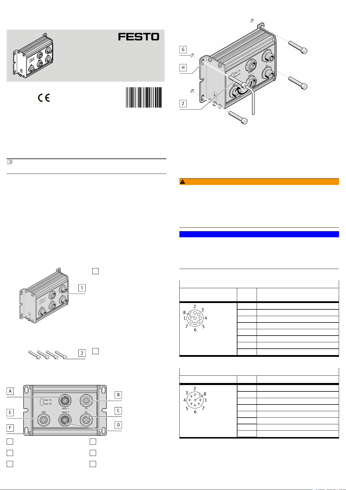
1Sensor interface (1x)
Fig. 1 CASB-MT-D3-R7
4.1.2 Not included in the delivery
2Screw (4x)
M4
Fig. 2 Retaining screws
4.2 Connecting components
AConnection socket DNCI-...-BA
Sensor 1
BConnector plug for safety relay unit
for TTL signals
CConnector plug for safety relay unit
for HTL signals
DConnection socket DNCI-...-BA
Sensor 2
EConnector plug VPCB-...-T22
Valve unit
FEarth connection
Fig. 3 Connecting component
5 Wall mounting
Fig. 4
1. Select screws2 select screws suitable for the installation situation.
2. Prepare the thread[G] on the mounting surface.
3. Mount the sensor interface1 via the slotted holes[H] using screws2 in the
threads[G]. Tightening torque: £3Nm
6 Electrical installation
6.1 Safety
WARNING!
Risk of injury due to electric shock.
• For the electrical power supply, use only PELV circuits in accordance with IEC
60204-1/EN 60204-1 (Protective Extra-Low Voltage, PELV).
• Observe the general requirements of IEC 60204-1/EN60204-1 for PELV cir-
cuits.
• Only use voltage sources that ensure a reliable electric separation from the
mains network in accordance with IEC 60204-1/EN 60204-1.
NOTICE!
Malfunction due to electromagnetic interference.
Incorrect measuring results and incorrectly stated positions.
• Use permitted lines without extensions.
• Lay permitted lines with sufficient clearance from lines with high noise level.
• Connect the earth terminal with low impedance to the earth potential.
6.2 Contact assignment
Socket [A], socket [D] M12, 8-pin
Connection sensor1,
sensor2
Pin Signal
1 5V DC
2 0V
3 Sin +
4 Sin –
5 Cos –
6 Cos +
7 Shield
8 n.c.
Tab. 1 Contact assignment sensor 1, sensor 2
Plug[B] M12, 8-pin
Connection TTL Pin Signal
1 n.c.
2 0V
3 A+
4 A–
5 B+
6 B–
7 n.c.
8 24V DC
Tab. 2 Contact assignment TTL
8084103
CASB-MT-D3-R7
Sensor interface
8084103
2018-07
[8084105]
Instructions| Assembly| Installation
Festo AG & Co. KG
Ruiter Straße 82
73734 Esslingen
Germany
+49 711 347-0
www.festo.com


