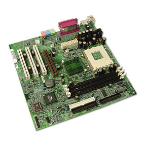
FIC PAK-2102 User manual

PAK-2102
PRELIMINARY
MANUAL
DOC No. : NA
Rev. : NA
Date : 1, 1997
Part No. : NA

i
Chapter 1 Overview
Main Features ............................................................................................. 2
Chapter 2 Installation Procedures
Mainboard Layout ...................................................................................... 6
1). Set System Jumpers ............................................................................... 7
Jumpers ............................................................................................. 7
Clear Password: CPW ............................................................... 8
Flash EPROM Type Selection: EP1, EP2 ................................. 8
2). Install RAM Modules ............................................................................ 9
DRAM Memory ................................................................................ 9
RAM Module Configuration ............................................................. 10
Install SIMMs ................................................................................... 12
Remove SIMMs ................................................................................ 13
Cache Memory .................................................................................. 14
Onboard Cache RAM (256KB/512KB) ............................................ 15
Onboard Cache RAM and RAM Module Mixture (512KB/1MB) .... 16
RAM Module .................................................................................... 17
3). Install the CPUs ..................................................................................... 18
CPU External Clock (Bus) Frequency: CLK1, CLK2 ............... 20
CPU to Bus Frequency Ratio: FREQ1, FREQ2 ........................ 20
Intel Pentium CPUs ................................................................... 21
Frequency ............................................................................. 21
Voltage ................................................................................. 22
AMD-K5 CPUs ......................................................................... 23
Frequency ............................................................................. 23
Voltage ................................................................................. 24
Cyrix 6x86 CPUs ...................................................................... 25
Frequency ............................................................................. 25
Voltage ................................................................................. 26
IBM 6x86 CPUs ........................................................................ 27
Frequency ............................................................................. 27
Voltage ................................................................................. 28
Installation of Cyrix (or IBM) 6x86 CPU Fan .......................... 29
4). Install Expansion Cards ......................................................................... 30
Table of Contents

PAK-2102 Mainboard Manual
ii
5). Connect Cables and Power Supply ........................................................ 31
Audio-In Connector: CD-IN ..................................................... 31
Serial Port Connectors: COM1, COM2 .................................... 31
CPU Fan Connectors: FAN ....................................................... 32
Hardware MPEG Card Connector: FC, LPB ............................. 32
Floppy Diskette Drive Connector: FLOPPY ............................. 33
Front Panel Block Connector: F_PNL ...................................... 34
Audio and Game Connector: AUDIO&GAME ......................... 35
Infrared Connector: IR .............................................................. 35
Power Connector: POWER ....................................................... 36
IDE HDD Device Connectors:
PRIMARY and SECONDARY ................................................. 37
Printer Connector: PRINTER .................................................... 37
PS/2 Keyboard Connector: PS2_KB ......................................... 38
PS/2 Mouse Connector: PS2_MS ............................................. 38
Remote Power Connector: RPW_CON ..................................... 39
Universal Serial Bus Connector: USB1 and USB2
(Reserved For Future Upgrade) ................................................. 39
VGA Connector: VCA .............................................................. 40
VGA Subsystem ................................................................... 40
Display ................................................................................. 41
The Connector ...................................................................... 42
Wave Table Connector: WAVE ................................................ 42

1
Overview
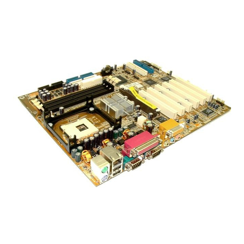
Congratulations on your decision to adopt the PAK-2102 mainboard. The
mainboard combines the advanced capabilities of the VIA Apollo 580VP®
chipset with a high-performance concurrent PCI local bus architecture to provide
the ideal platform for unleashing the unsurpassed speed and power of the Intel
Pentium processor. This highly-flexible mainboard is designed to run a full range
of Intel Pentium™, Cyrix 6x86™, IBM 6x86™, and AMD-K5™ processors;
and can be easily upgraded using its 321-pin ZIF socket. The processor's
advanced performance is complemented by a second level write back Pipeline
Burst SRAM cache of up to 1MB and main memory of up to 512MB RAM. The
main memory is installed using the board's six 72-pin SIMM sockets that accept
an unrivaled choice of high-speed EDO and standard Fast Page Mode DRAM.
The PAK-2102 integrates a full set of I/O features onboard, including two 16550
UART compatible serial ports, one EPP/ECP capable parallel port, and one
Floppy Disk Drive controller. It also comes with a built-in Enhanced IDE
controller that provides convenient, high-speed PCI Bus Master connections
with up to four IDE devices, including Hard Disk and CD-ROM drives. An
extended slot allows you to install a riser card providing ample room for further
expansion. The mainboard also features support for the state-of-the-art Universal
Serial Bus (USB) that provides ease-of-use and high-speed Plug & Play
connections to future USB compliant peripheral devices. The IrDA compliant
serial port and optional onboard SIR support further enhance system I/O
connectivity. Moreover, for advanced VGA functionality, the PAK-2102
features an onboard S3 Trio64V+™ VGA subsystem that delivers up to
1024x768x256 resolutions. The Creative Lab ViBRA 16C™ onboard audio
subsystem provides the audio environment.
This chapter gives you a brief overview of the PAK-2102 mainboard. In addition
to basic information on the board's main components and features, it also
provides advice on how to upgrade and expand it. For updated BIOS, drivers, or
product release information, please visit FIC's home page at:
http://www.fic.com.tw.
Main Features
The PAK-2102 mainboard comes with the following high-performance features:
Chapter 1

PAK-2102 Mainboard Manual
2
Easy Installation
Phoenix BIOS with support for Plug and Play, auto detection of Hard Drive
and IDE features, and MS Windows 95™.
Flexible Processor Support
The onboard 321-pin ZIF socket supports Intel Pentium (P54C) CPU speed
75/90/100/120/133/150/166/200 MHz processors / P54CS / P54CTB /
P55.P55C.
.Cyrix 6x86-P120+ (100 MHz) / 6x86-P133+ (110 MHz) / 6x86-P150+
(120 MHz) / 6x86-P166+ (133 MHz) / M2 seris processors.
IBM 6x86-P120+ (100 MHz) / 6x86-P133+ (110 MHz) / 6x86-P150+
(120 MHz) / 6x86-P166+ (133 MHz) / M2 seris processors.
A...AMD K5-PR75 (75 MHz) / K5-PR90 (90 MHz) / K5-PR100 (100 MHz) /
K5-PR120 (90 MHz) / K5-PR133 (100 MHz) / K5-PR150 (105 MHz) /
K5-PR166 (116 MHz) / K5-PR200 (133 MHz) processors.
Leading Edge Chipset
VIA 580VP chipset, including a CPU interface controller, advanced
cache controller, integrated DRAM controller, synchronous ISA bus
controller, PCI local bus interface, integrated power management unit.
Ultra-fast Level II Cache
Supports onboard Pipeline Burst SRAM that can be expanded to 1MB
using a cache module.
Versatile Main Memory Support
Accepts up to 512MB RAM in threebanks using six SIMMs of 4, 8, 16, 32,
|| 32, 64, 128MB with support for FPM and EDO DRAM.
ISA & PCI Expansion Slots
An extend slot allows a riser card for further expansion.
USB Support (Reserved for Future Upgrade)
Two Unniversal Serial Bus plug-in connectors integrated into rear I/O
panel.
Table of contents
Other FIC Motherboard manuals

