FIC PA-2006 User manual

PA-2006
MAINBOARD
MANUAL
DOC No. : 15579
Rev. : A2
Date : 4, 1997
Part No. : 25-10580-05

i
Chapter 1 Overview
Main Features........................................................................................ 2
This User Manual .................................................................................. 4
Something Interesting............................................................................. 5
The BIOS Setup Utility................................................................. 5
IRQ Functionality.......................................................................... 6
DMA Channels of ISA Cards ........................................................ 7
Enhanced IDE............................................................................... 7
Serial Infrared (SIR) Connections.................................................. 8
Highly Convenient Integrated I/O Connectors................................ 9
Chapter 2 Installation Procedures
Mainboard Layout.................................................................................. 12
1). Set System Jumpers .......................................................................... 13
Jumpers ........................................................................................ 13
Clear Password: CPW............................................................ 14
Flash EPROM Type Selection: EP1, EP2............................... 14
CPU to SRAM Data Transacting Mode Selection: SRAM3 ... 15
2). Install DRAM Modules..................................................................... 16
DRAM and SDRAM..................................................................... 16
RAM Module Configuration.......................................................... 17
Install SIMMs............................................................................... 20
Remove SIMMs............................................................................ 20
Install DIMMs .............................................................................. 21
Remove DIMMs............................................................................ 21
Cache Memory.............................................................................. 22
Install Cache SRAM Module......................................................... 22
Onboard Cache SRAM (256KB/512KB) ....................................... 23
Onboard Cache SRAM and SDRAM Module Mixture
(512KB/1MB)............................................................................... 24
SRAM Module (256KB/512KB)................................................... 25
3). Install the CPUs................................................................................ 26
System Clock Selection:
CLK1, CLK2, CLK3.............................................................. 27
Table of Contents

PA-2006 Mainboard Manual
ii
CPU to Bus Frequency Ratio Selection:
FREQ1, FREQ2..................................................................... 27
Intel Pentium CPUs............................................................... 28
Frequency......................................................................... 28
Voltage............................................................................. 29
AMD-K5/K6 CPUs................................................................ 30
Frequency......................................................................... 30
Voltage............................................................................. 31
Cyrix 6x86 CPUs................................................................... 32
Frequency......................................................................... 32
Voltage............................................................................. 33
IBM 6x86 CPUs.................................................................... 34
Frequency......................................................................... 34
Voltage............................................................................. 35
Installation of Cyrix (or IBM) 6x86 CPU Fan......................... 36
4). Install Expansion Cards .................................................................... 37
5). Connect Cables and Power Supply .................................................... 39
Keyboard Connector: AT_KB ................................................ 39
Serial Port Connectors: COM1 and COM2............................. 39
CPU Fan Connectors: FAN.................................................... 40
Floppy Diskette Drive Connector: FLOPPY ........................... 40
Front Panel Block Connector: F_PNL .................................... 41
Infrared Connector: IR ........................................................... 42
Outlet Connector: OUTLET................................................... 42
Power Connector: POWER .................................................... 43
IDE HDD Device Connectors:
PRIMARY and SECONDARY .............................................. 44
Printer Block Connector: PRINTER....................................... 44
Remote Power Connector: RPW_CON................................... 45
Universal Serial Bus Connector: USB1 and USB2
(Reserved For Future Upgrade).............................................. 45
Chapter 3 Award BIOS Setup
CMOS Setup Utility............................................................................... 47
Standard CMOS Setup........................................................................... 48
BIOS Features Setup.............................................................................. 50

Installation Procedures
iii
Chipset Features Setup........................................................................... 53
Power Management Setup...................................................................... 58
PCI Configuration Setup......................................................................... 61
PnP Configuration Setup........................................................................ 63
Load BIOS Defaults............................................................................... 64
Load Setup Defaults............................................................................... 64
Supervisor/User Password...................................................................... 64
IDE HDD Auto Detection....................................................................... 65
Save and Exit Setup............................................................................... 66
Exit without Saving................................................................................ 66
Appendix A Applicatin Note

PA-2006 Mainboard Manual
iv
This Page Intentionally Left Blank

1
Overview
The PA-2006 mainboard combines the advanced capabilities of the VIA 580VP
chipset with a high-performance concurrent PCI local bus architecture to
provide the ideal platform for unleashing the unsurpassed speed and power of
the Intel Pentium processor.
This highly-flexible mainboard is designed to run a full range of Intel Pentium,
Cyrix 6x86 (M1/M2), IBM 6x86 (M1/ M2), and AMD-K5/K6 processors, and
can be easily upgraded using its 321-pin ZIF socket. The processor's advanced
performance is complemented by a second level write back Pipeline Burst
SRAM cache of up to 1MB (by one cache RAM module slot for 1MB PBSRAM
cache module) and main memory of up to 384MB DRAM. The main memory is
installed using the board's two 72-pin SIMM sockets and two 168-pin DIMM
sockets that accept a choice of lightning-fast synchronous DRAM (SDRAM)
and high-speed EDO DRAM.
The PA-2006 integrates a full set of I/O features onboard, including two
16550A UART compatible serial ports, one EPP/ECP capable parallel port, and
one Floppy Disk Drive controller. It also comes with a built in Enhanced IDE
controller that provides convenient, high-speed PCI Bus Master connections
with up to four IDE devices, including Hard Disk and CD-ROM drives. Four
16-bit ISA slots and four 32-bit PCI slots provide ample room for further
expansion. The mainboard also features support for the state-of-the-art
Universal Serial Bus (USB) that provides ease-of-use and high-speed Plug &
Play connections to future USB compliant peripheral devices. The IrDA
compliant serial port and onboard SIR support further enhance system I/O
connectivity.
This chapter gives you a brief overview of the PA-2006 mainboard. In addition
to basic information on the board's main components and features, it also
provides advice on how to upgrade and expand it. For updated BIOS, drivers,
or product release information, please visit FIC's home page at:
http://www.fic.com.tw.
Chapter 1

PA-2006 Mainboard Manual
2
Main Features
The PA-2006 mainboard comes with the following high-performance features:
nEasy Installation
Award BIOS with support for Plug and Play, auto detection of Hard Drive
and IDE features, MS Windows 95, and Windows NT compatible.
nFlexible Processor Support
Onboard 321-pin ZIF socket and switching voltage regulator support
complete range of leading-edge processors:
Intel Pentium75MHz – 200MHz (P55C with MMXtechnology;
P54C/P54CS)
AMD-K6-PR166 – PR233
AMD-K5-PR75 – PR166
Cyrix M2 Series processors
Cyrix 6x86-PR120+ – PR200+*
IBM M2 Series processors
IBM 6x86-PR120+ – PR200+*0.
NOTE : * Support for Cyrix 6x86-PR200+ and IBM 6x86-PR200+ is optional.
nLeading Edge Chipset
VIA 580VP chipset, including a CPU interface controller, advanced
cache controller, integrated DRAM controller, synchronous ISA bus
controller, PCI local bus interface, integrated power management unit.
nUltra-fast Level II Cache
Supports onboard 256KB/512KB synchronous PBSRAM cache memory
and one cache module slot for 1MB PBSRAM cache module.
nVersatile Main Memory Support
Accepts up to 256MB RAM in one bank using 72-pin SIMMs of 4, 8, 16,
32, 64, 128MB or up to 128MB RAM in two banks using two 168-pin
DIMMs of 8, 16, 32, 64MB with support for SDRAM and EDO memory.
nISA & PCI Expansion Slots
Four 16-bit ISA and four 32-bit PCI expansion slots provide all the room
you need to install a full range of add-on cards.

Overview
3
nUSB Support
Onboard support for two Universal Serial Bus connectors via a plug-in
connector.
nEnhanced PCI Bus Master IDE Controller
Integrated Enhanced PCI local bus IDE controller with two connectors
supports up to four IDE devices such as Hard Disk, CD-ROM or Tape
Backup drives via two channels for high speed data throughput. This
controller supports PIO Modes 3 and 4, and DMA Mode 2 for optimized
system performance.
nSuper Multi I/O
Integrated Winbond 83877F chipset features two 16550A UART
compatible serial ports, one EPP/ECP capable parallel port, one IR port,
and
one Floppy Disk Drive connector.

PA-2006 Mainboard Manual
4
This User Manual
This manual is designed to guide you and facilitate your use of the PA-2006
mainboard. It contains a description of the design and features of the
mainboard, and also includes useful information for changing the configuration
of the board and the system it is installed in. The manual is divided into three
chapters:
nChapter 1 - Overview
gives an overview of the mainboard and describes its major components
and features.
nChapter 2 - Installation Procedures
gives instructions on how to set up the mainboard, including jumper
settings and CPU installation guides.
nChapter 3 - Award BIOS Setup
briefly explains the mainboard's BIOS system setup in general and tells
you
how to run it and change the system configuration settings.
NOTE : The material in this manual is for information only and is subject to
change without notice. We reserve the right to make changes in the product
design without reservation and without notification to its users. We shall not be
liable for technical or editorial omissions made herein; nor for incidental or
consequential damages resulting from the furnishing, performance, or use of
this material.

Overview
5
Something Interesting
This section provides useful information that you will need to know should you
decide to modify or upgrade the configuration of the mainboard and the system
it is installed in. If you do not have the confidence to upgrade the mainboard
yourself, we advise that you consult a qualified service technician for
assistance.
The BIOS Setup Utility
The BIOS (Basic Input Output System) is the basic firmware that instructs the
computer how to operate. For the BIOS to work properly, there must be a
record of the computer's hardware and configuration settings for it to refer to.
This record is created using the Setup Utility, a program that is stored
permanently in the BIOS ROM chip on the mainboard.
The system configuration record created by the Setup Utility is also stored on
the mainboard, but not permanently. This section of the memory it is stored is
in the NVRAM.
When you buy your computer, the system configuration record will already be
set and may in some cases differ from the basic defaults. The first time you use
your computer or when you need to re-configure your system, you should run
the Setup Utility and write down the settings.

PA-2006 Mainboard Manual
6
IRQ Functionality
As you read through this manual, you will see the term IRQ on a number of
occasions. It is important for you to know what this term means, particularly if
you intend to upgrade your system.
IRQ stands for Interrupt Request, the process in which an input or output
device tells the processor to temporarily interrupt its current task and
immediately process something from the source of the interrupt. When it has
completed this, the processor returns to the task it was already processing.
Devices that need an
IRQ line to operate sometimes need to have exclusive use of that line.
A large number of add-on cards, such as sound cards and LAN cards, require
the use of an IRQ line to function. Some of IRQs may already be in use by
components in the system such as the keyboard and mouse. Add-on cards that
need to use an IRQ draw from the unused group of IRQs. When installing a
card that uses an IRQ, it will have a default IRQ setting which you might have
to change if that IRQ is already in use and cannot be shared.
Both ISA and PCI add-on cards may need to use IRQs. System IRQs are
available to add-on cards installed on the ISA bus first; the remaining ones can
be used by cards installed on the PCI bus. There are two categories of ISA add-
on cards: so-called Legacy ISA cards, which need to be configured manually
and then installed in any available ISA slot; and Plug and Play (PnP) ISA
cards, which are configured automatically by the system. As a result, when you
install Legacy ISA cards, you have to carefully configure the system to ensure
that the installed cards do not conflict with each other by having the same IRQ.
With PnP cards, on the other hand, IRQs are assigned automatically from the
ones available in the system. In the case of PCI add-on cards, the BIOS
automatically assigns an IRQ card to the PCI slot the card is installed in.

Overview
7
DMA Channels of ISA Cards
Some Legacy and PnP ISA add-on cards may also need to use a Direct Memory
Access (DMA) channel. DMA assignments for this mainboard are handled in
the same way as the IRQ assignment process outlined above. For more
information, please refer to Chapter 3 of this manual.
Enhanced IDE
This mainboard features an integrated Enhanced IDE controller that provides
convenient, high-speed connections with up to four IDE devices, such as Hard
Disk, CD-ROM and Tape Backup Drives. Enhanced IDE is an upgrade of the
original IDE specification and provides increased capabilities and performance
in a number of areas, including support for Hard Disk Drives of over 1.2GB
and faster data transfer rates utilizing the PIO Mode 4 timing scheme.
With the integrated IDE controller you can connect up to four IDE peripheral
devices to your system. All devices are categorized in the same way that IDE
Hard Disks were configured in the past, with one device set as the Master
device and the other as the Slave device. We recommend that Hard Disk Drives
use the Primary IDE connector and that CD-ROM drives utilize the Secondary
IDE connector for improved system performance.

PA-2006 Mainboard Manual
8
Serial Infrared (SIR) Connections
This mainboard features support for highly-sophisticated SIR technology,
which allows bi-directional and cordless data transactions with other IrDA
compliant computers and peripheral devices using infrared as a medium. This
transmission is carried out in either Full Duplex Mode or Half Duplex Mode.
The former allows simultaneous data transmission and reception, while the
latter disables the reception when transmission occurs.
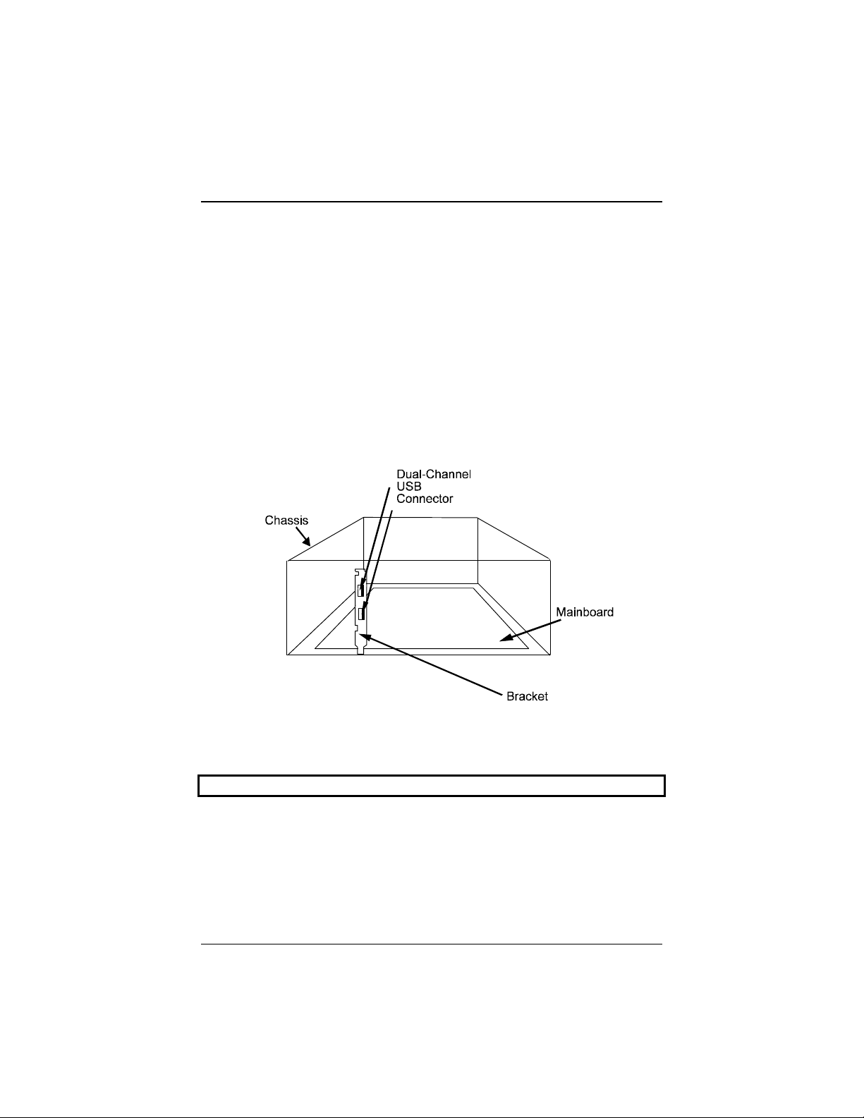
The I/O chipset on this mainboard features a SIR interface that is fully
compliant with the IrDA standard. An IrDA device can be installed via a 9-pin
D-SUB connector in the rear panel of the computer which is linked by a cable
to the onboard IrDA pinhead, as shown in the illustration below.
The serial port COM2 on this mainboard is designed to be a SIR compliant
port. If you wish to install the SIR connection feature, you need to adjust the
BIOS option for high-speed performance.
Overview
9
Highly Convenient Integrated I/O Connectors
This mainboard features has an integrated rear I/O panel that incorporates a
full set of I/O ports to allow simple and convenient connections to a complete
selection of external peripheral devices.
In addition to two 16550A UART compatible serial ports and one EPP/ECP
capable parallel port, the panel features two USB connectors that provide high
speed connection to the next generation of USB devices. PS/2 keyboard and
PS/2 mouse connectors provide additional I/O connectivity.
NOTE : USB Feature is reserved for future upgrade.

PA-2006 Mainboard Manual
10
This Page Intentionally Left Blank

11
Installation Procedures
The PA-2006 has several user-adjustable jumpers on the board that allow you to
configure your system to suit your requirements. This chapter contains
information on the various jumper settings on your mainboard.
To set up your computer, you should follow these installation steps:
nStep 1 -
Set system jumpers
nStep 2 -
Install RAM modules
nStep 3 -
Install the CPU
nStep 4 -
Install expansion cards
nStep 5 -
Connect cables and power supply
nStep 6 -
Set up BIOS feature (Please read Chapter Three.)
Chapter 2

PA-2006 Mainboard Manual
12
Mainboard Layout

Installation Procedures
13
1). Set System Jumpers
Jumpers
Jumpers are used to select the operation modes for your system. Some jumpers
on the board have three metal pins with each pin representing a different
function. To set a jumper, a black cap containing metal contacts is placed over
the jumper pin/s according to the required configuration. A jumper is said to be
shorted when the black cap has been placed on one or two of its pins. The types
of jumpers used in this manual are shown below:
NOTE : Users are not encouraged to change the jumper settings not listed in
this manual. Changing the jumper settings improperly may adversely affect
system performance.

PA-2006 Mainboard Manual
14
Clear Password: CPW
This jumper allows you to set the password configuration to Enabled or
Disabled. You may need to enable this jumper if you forget your password.
PCI2 ID: PCI2ID
This setting is provided to allow you to install more than one PCI add-on card
released before the launch of the PCI Encoding Standard in 1993.
NOTE : Please be aware that this feature is only provided for reasons of
convenience and it is only in rare cases that the user needs to alter the default
setting. Please consult your dealer for further information.

Installation Procedures
15
CPU to SRAM Data Transacting Mode Selection: SRAM3
This jumper allows you to select the CPU to SRAM data read/write mode.
Also, you need to configure the Chipset feature, Linear Bust Mode, in Page
54. Please refer to it.
Table of contents
Other FIC Motherboard manuals


Popular Motherboard manuals by other brands

Gigabyte
Gigabyte GA-78LMT-S2P user manual

abaco systems
abaco systems XVR16 Series Hardware reference manual

Asus
Asus P8H61-M PLUS2 user manual

Intel
Intel D850GB Technical product specification

Xilinx
Xilinx Virtex UltraScale FPGA VCU1287 Getting started guide

Super Micro General
Super Micro General X11SSM user manual


