FIC PAG-2130 User manual

1-1
Overview
The 1stMainboard PAG-2130 is a MicroATX-sized Super 7 solution
offering high performance, the highest speeds for super 7 processors and
the very latest in quality onboard features. It supports the AMD® K6™-III
400-450 MHz @ 100 MHz Front Side Bus and Pentium® MMX, AMD®
K6, AMD® K6-2,Cryix MII 300-366, IBM and IDT WinChip processors.
The PAG-2130 is based around the advanced architecture of the VIA
MVP4 and Super South chipset, giving advanced levels of performance
with high quality audio/visual capabilities. The PAG-2130 comes with a
standard 1MB (manufacturing option: 2MB/512KB) of on-board cache.
With up to 2MB of SRAM cache on-board, the AMD K6-III 400-450MHZ
processors will significantly boot the PC’s performance.
The Super South chipset is a PC98 compliant PCI Super-I/O integrated
peripheral controller with integrated super-I/O, USB controller (with
support for four USB ports), keyboard controller, RTC, plug and play,
ACPI, enhanced power management, and temperature, voltage, and fan-
speed monitoring. With support for the new Ultra DMA66 protocol and its
high-speed interface, data transfer speeds and hard drive performance are
significantly improved.
The PAG-2130 has 3 DIMM for up to 768 MB SDRAM, and also offers
ECC memory support. It is equipped with, 4 PCI, and 1 ISA expansion slot.
The PAG-2130 is fully PC99 and Y2K compliant, and is ACPI ready,
ensuring improved energy efficiency. Other features include Wake-On-
LAN, IrDA, Intel LDCM software (manufacturing option) and CD Pro
with enhanced drivers. For the most up-to-date information about your
mainboard and the latest FAQs and BIOS updates, visit FIC Online at
http://ww.fic.com.tw.
Chapter 1

PAG-2130 Mainboard Manual
1-2
Package Checklist
Please check that your package contains all the items listed below. If you
discover that any item is damaged or missing, please contact your vendor.
üThe PAG-2130 mainboard
üThis user’s manual
üOne IDE ribbon cable
üOne floppy disk drive ribbon cable
üOne ribbon cable with bracket for COM2 connector
üSoftware utilities
Overview
1-3
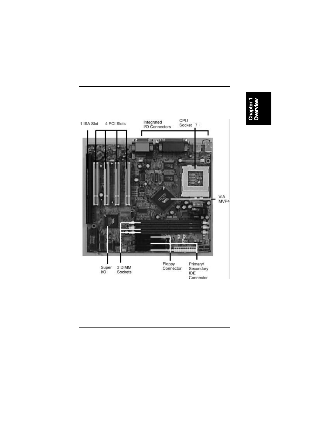
The PAG-2130 Mainboard

PAG-2130 Mainboard Manual
1-4
Main Features
The mainboard comes equipped with the most advanced new features that
not only optimize the performance of the latest processors but also enhance
the manageability, power management capabilities, and user-friendliness of
your system. This section provides detailed information on these features,
and how they are implemented on the mainboard.
nEasy Installation
Award BIOS with support for Plug and Play, auto detection of IDE
hard drives, LS-120 drives, MS Windows® 95, Windows® 98,
Windows® NT, and OS/2.
nFlexible Processor Support
Onboard 321-pin ZIF socket and switching voltage regulator support
complete range of leading-edge processors:
Intel Pentium 100 -160MHz, AMD K5 100 –200MHz, Intel Pentium
MMX 166 –233MHz, Cyrix /IBM PR166 –PR266MHz, AMD K6
166 - 300MHz, AMD K6-2 266 –475MHz, AMD K6-3 400/450MHz,
or Cyrix MII 300 –366MHz processors.
nVarious External Bus and CPU/Bus Frequency Ratio Support
The motherboard supports the Bus frequency of
66/66.8/75/83/95/100/105MHz and the CPU/Bus frequency ratio of
1.5x//2x/2.5x/3x/3.5x/4x/4.5 x/5x/5.5x by a switching voltage
regulator which accepts from 1.8V to 3.5V.||(Please read Install the
CPU in Chapter 2 for more information).
nUltra-fast Level II Cache
Supports up to 2MB onboard Pipeline Burst Level II write-back cache.
nLeading Edge Chipset
VIA APOLLO MVP4 chipset with integrated DRAM and L2 cache
controllers as well as support for Intel's new Dynamic Power
Management Architecture (DPMA), Concurrent PCI (PCI 2.0 and 2.1),
AGP 1.0 compliant, and USB.

Overview
1-5

PAG-2130 Mainboard Manual
1-6
nVersatile Main Memory Support
Accepts up to 768MB DRAM in three banks using DIMMs of 8, 16,
32, 64, 128, and 256MB with support SDRAM (66MHz and 100MHz)
memory.
nOnboard IrDA Connector
An IrDA connector for wireless infrared connections is available.
nLightning-fast SDRAM Performance
The mainboard supports 66MHz and the new generation of lightning-
fast 100MHz SDRAM via its onboard 168-pin DIMM sockets.
SDRAM delivers an added boost to overall system performance by
increasing the CPU-to-memory data transfer rate. SDRAM
performance on the mainboard is further boosted by it’s integrated I2C
controller, which optimizes the memory timing settings. Besides, the
latest Virtual Channel Memory (VCM) is also supported on the
mainboard.
nUSB Support
Two USB ports integrated in the rear I/O panel allow convenient and
high-speed Plug and Play connections to the growing number of USB
compliant peripheral devices on the market. One manufacturing
optional USB connector that shared with one USB port for the front
panel.
nSuper Multi Input/Output (I/O) Support
Integrated VT82C686 super multi-I/O chipset features one high-speed
UART 16550 compatible serial port and one serial connector, one
EPP/ECP capable parallel port, and one Floppy Disk Drive connector.
It is also IrDA 1.0 compliant.
nRemote Wake On LAN Support
Onboard WOL connector allows remote management on your network
even the system is power off. This feature provides a simpler and
convenient control to LAN-based networks.

Overview
1-7
nIntel LANDesk Client Manager (LDCM) Software Support
(optional)
LDCM is a DMI-compliant application for local and network
management of desktop client systems. The application reduces the
number of help desk calls by supplying the user with self diagnostics
such as a PC health meter and local alert of potential problems.
ACPI Ready
This mainboard fully implements the new ACPI (Advanced Configuration
and Power Interface) 1.0 Hardware and BIOS requirement. If you install
ACPI-aware operating systems, such as Windows® 98, you can fully utilize
the power saving features under ACPI. It is compatible with all other non
ACPI-aware operating systems.
If you want to setup ACPI features under Windows® 98, please follow the
instructions below:
Run Windows® 98 setup by typingsetup /p j at the command prompt for
installing Windows® 98 with the ACPI control features.
If you type setup without the parameter /p j, Windows® 98 will be installed
as APM, PnP mode, no ACPI will be used.
For more detailed information, please visit the web site of Microsoft. The
URL is http://www.microsoft.com/hwtest/.
The following are a few examples about the advantages of ACPI -
nSoft-Off Support
The mainboard’s Soft-Off feature allows you to turn off your computer
using the operating system. This feature requires a power supply with
a soft-off power controller.
nRemote Ring-On
The Remote Ring-On function allows your computer to be turned on
remotely via a modem while it is in sleep mode. This feature is
particularly useful when you are expecting a fax late at night and leave
only your modem on to minimize power consumption. As soon as the
phone rings, the modem automatically turns on the system, which
answers the phone and downloads the fax. Then the computer shuts

PAG-2130 Mainboard Manual
1-8
down again, thereby minimizing its power consumption. The Remote
Ring-On function requires a power supply with a soft-off power
controller.
nRTC Alarm
The RTC alarm feature allows you to preset the computer to wake-up
at a certain time to implement a number of useful functions, such as
sending out a fax late a night automatically.

Overview
1-9
This Page Left Blank for Notes

2-1
Installation Procedures
The mainboard has several user-adjustable jumpers/switches on the board
that allow you to configure your system to suit your requirements. This
chapter contains information on the various hardware settings on your
mainboard.
To set up your computer, you should follow these installation steps:
nStep 1 - Set system jumpers/switches
nStep 2 - Install memory modules
nStep 3 - Install the CPU
nStep 4 - Install expansion cards
nStep 5 - Connect devices
nStep 6 - Set up BIOS features
WARNING: If you use an electric drill to install this
mainboard on your chassis, please wear a static wrist
strap. The recommended electric drill torque is from 5.0
to 8.0 kg/cm to avoid damaging the chips’pins.
Chapter 2

PAG-2130 Mainboard Manual
2-2
This Chapter is intended to aid quick and easy installation.
In the event that more detailed information is required, please
consult the Installation Procedures Chapter.
Installation Procedures
2-3

PAG-2130 Mainboard Manual
2-4

Installation Procedures
2-5
2).CPU Fan Installation
This connector is linked to the CPU fan. When the system is in suspend mode,
the CPU fan will turn off; when it reverts back to full on mode, the fan will
turn back on. Without sufficient air circulation, the CPU may overheat and
cause damage to both the CPU and the mainboard.
NOTE: Damage may occur to the mainboard and/or the
CPU fan if these pins are incorrectly used. These are not
jumpers, do not place jumper caps over these pins.
3).Front Panel Block Cable Connection
This connector is linked to the CPU fan. When the system is in suspend
mode,
4).Other Enabled/Disabled Jumpers

PAG-2130 Mainboard Manual
2-6
5).Load BIOS Setup Default
Load BIOS Defaults
BIOS defaults contain the most appropriate values of the system parameters
that allow minimum system performance. The OEM manufacturer may
change the defaults through MODBIN before the binary image burns into
the ROM.
Load Setup Defaults
Selecting this field loads the factory defaults for BIOS and Chipset Features
which the system automatically detects.
6).How to Upgrade BIOS
1. Format a bootable system floppy diskette by typing format a:/s at
the command prompt.
2. Visit the the web site of the vendor and visit the BIOS Update
page in the related Technical Support section.
3. Select the BIOS file you need and download it to your bootable
floppy diskette.
4. Insert the bootable diskette containing the BIOS file into the
floppy diskette drive.
5. Assuming that the floppy diskette drive is A, reboot the system by
using the A: drive. At the A: > prompt, run the BIOS upgraded
file by executing the Flash BIOS utility and the BIOS file with its
appropriate extension.
Do not turn off or reset the computer during the flash
process or there will be a problem booting up your system.

Installation Procedures
2-7
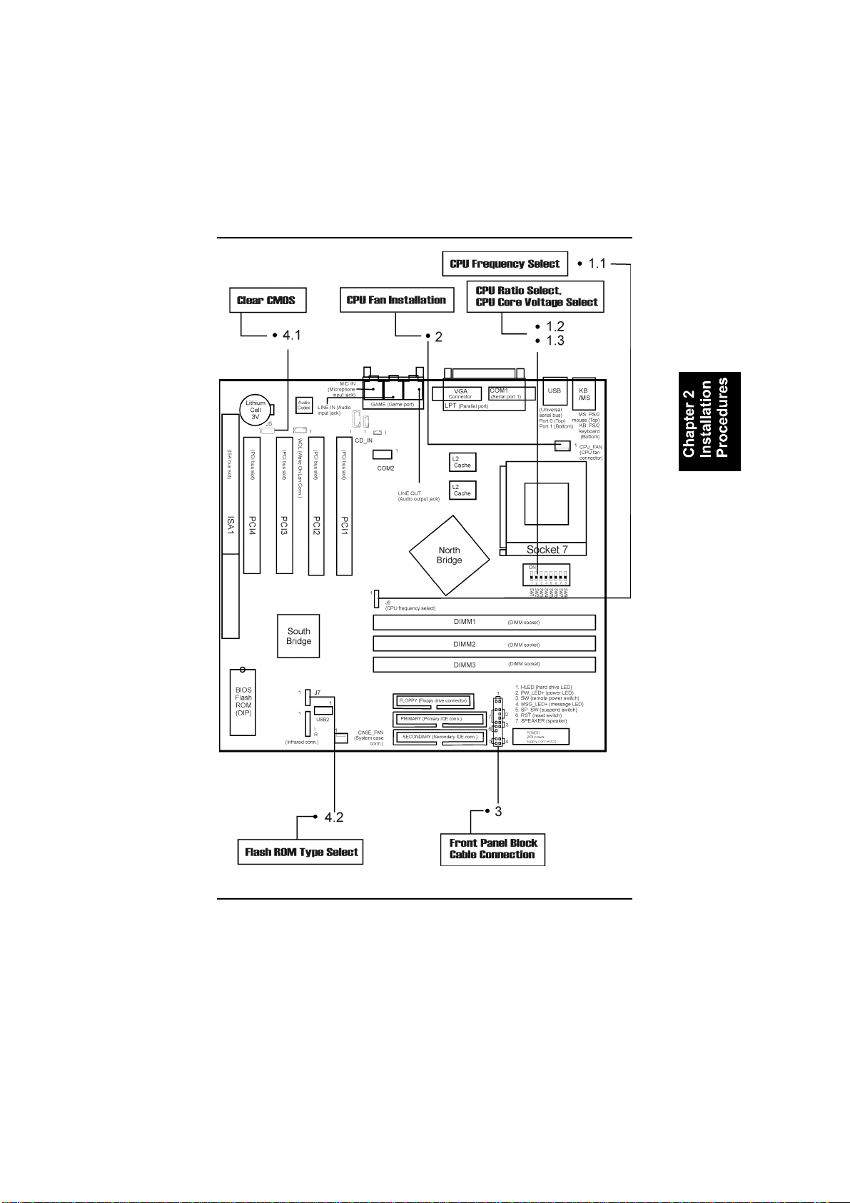
Mainboard Layout

PAG-2130 Mainboard Manual
2-8
Onboard Mark FUNCTION PAGE
J5 Clear CMOS Data 2-9
J7 Flash ROM Type Selection 2-10
DIMM1/2/3 DIMM Memory Module Support 2-11
J6 CPU Internal Frequency Selection 2-14
SW1/2/3 CPU Ratio Selection 2-15
SW4/5/6/7/8 CPU to Bus Frequency Ratio Selection 2-16
PCI1/2/3/4 PCI Bus Expansion Slot (32-bit) 2-17
ISA1 ISA Bus Expansion Slot (16-bit) 2-17
FLOPPY Floppy Diskette Drive Connector 2-18
PRIMARY,
SECONDARY IDE Device Connector 2-18
POWER ATX Power Connector 2-19
CPU_FAN CPU Fan Connector 2-20
WOL Wake-On-LAN Connector 2-22
*Front Panel Block
Connector Connectors for LEDs and Switches on Front
Panel 2-23
CASE_FAN Power Supply Fan Connectors 2-24
KB PS/2 Keyboard Connector 2-25
MS PS/2 Mouse Connector 2-25
COM1/2 Serial Port 2-25
USB0/1/2 Universal Serial Bus Connector 2-26
IR Infrared Port Module Connector 2-27
CD_IN CD-ROM Drive Audio-out Connector 2-27
LPT Printer Connector 2-28
GAME Joystick/MIDI Connector 2-28
MIC IN Audio Microphone Jack 2-29
LINE IN Audio Line-In Jack 2-29
LINE OUT Audio Line-Out Jack 2-29
* includes IDE LED, power LED, remote power button, message LED,
suspend button, reset button and speaker (See Page 2-23 for more
information.)

Installation Procedures
2-9
1). Set System Jumpers/Switches
Clear CMOS: J5
The CMOS RAM is powered by the onboard button cell battery. To clear
the RTC data: (1). Turn off your computer, (2). Enable this feature by
placing the jumper cap to 2-3 pins on J5, or (3). Disable this feature by
placing the jumper cap to 1-2 pins on J5, (4). Turn on the computer, (5).
Hold down the Delete key when boots and enter BIOS Setup to re-enter
user preferences.

PAG-2130 Mainboard Manual
2-10
Flash ROM Type Selection: J7
This jumper allows you to configure the type of flash ROM chip. This
jumper setting is correct by manufactory default. If you want to know the
flash ROM type installed on this mainboard, remove the sticker from the
chip to see its type.

Installation Procedures
2-11
2). Install RAM Modules
RAM Module Configuration
PC100 modules may have a serial EEPROM containing a number of
critical timing parameters and data regarding the chip and module vendor.
This guarantees that the VIA MVP4 chipset will properly recognize the
module by reading all of the important timing parameters specified in the
EEPROM over the serial presence detect interface. The module supplier
must understand these differences in detail and provide the correct
information so that the VIA MVP4 chipset will be programmed properly to
control the memory.
This mainboard provides three onboard DIMM sockets for allowing only
3.3V (unbuffered) SDRAM DIMM modules and supports DIMMs with
data access time of 12ns, 10ns, 8ns or less. ECC memory and parity check
are also supported. If DIMM runs at the speed of 100MHz, it must meet the
PC100 Specification. Either 8, 16, 32, 64, 128MB, or 256MB DIMM can
be installed on these three sockets. (Please use the same memory sizes of
DIMM on each socket for better performance.) The maximum total memory
supported is up to 768MB.
Socke
tAcceptable Memory Module
Acceptable Memory Module Total
Memory
18/16/32/64/128/256MB 168-pin 3.3V SDRAM x1
28/16/32/64/128/256MB 168-pin 3.3V SDRAM x1
38/16/32/64/128/256MB 168-pin 3.3V SDRAM x1
Total System Memory allowed up to 768MB =
NOTE: The latest Virtual Channel Memory (VCM) SDRAM
is also supported on this mainboard. Thus with the use of
VCM-SDRAMs, memory performance can be greatly
enhanced.
Table of contents
Other FIC Motherboard manuals


