FIC KT-748 User manual

KT-748
MAINBOARD
MANUAL
DOCNo.: M03403
Rev. :A0
Date:6,2003
PartNo.:25-11663-00

Handling Precautions
Warning:
1.Staticelectricitymaycausedamage tothe integrated circuitson
the motherboard.Beforehandling anymotherboardoutside ofits
protectivepackaging,ensurethatthereisno staticelectric
charge inyourbody.
2.Thereisadangerofexplosion ifthe batteryisincorrectly
replaced.Replaceonlywiththe sameoran equivalenttype
recommended bythe manufacturer.
3.Discardused batteriesaccording tothe manufacturer’s
instructions.
4.Neverrun the processorwithoutthe heatsinkproperlyand firmly
attached.PERMANENTDAMAGEWILLRESULT!
Observethefollowing basicprecautionswhenhandling themotherboard
orothercomputercomponents:
nWearastaticwriststrapwhichfitsaround yourwristand is
connectedtoanaturalearthground.
nTouchagroundedoranti-staticsurface orametalfixturesuchasa
waterpipe.
nAvoidcontacting thecomponentson add-on cards,motherboards,
and moduleswiththegoldenfingers connectorspluggedintothe
expansion slot.Itisbesttohandlesystemcomponentsby their
mounting brackets.
Theabovemethodspreventstaticbuild-up and causeit tobedischarged
properly.
Trademark
All trademarksmentionedinthismanualareregisteredproperlyof
therespective owners.
Handling Precautions
Thismanualmaynot,inwholeorinpart,bephotocopied,reproduced,
transcribed,translated,ortransmittedinwhateverformwithoutthe
writtenconsentofthemanufacturer,exceptforcopiesretainedbythe
purchaserforpersonalarchivalpurposes.
Notice

i
TableofContents
TableofContents
Chapter1Overview
PackageChecklist......................................................................... 1-2
TheKT-748 Mainboard............................................................. 1-3
MainFeatures............................................................................... 1-4
FICUniqueInnovation forUsers(NOVUS)-
EnhancedMainboardFeaturesand SystemSupport..................... 1-5
Chapter2Installation Procedures
1).SetSystemJumpers.................................................................. 2-2
ClearCMOS...................................................................... 2-2
BIOSAnti-ReflashProtect................................................ 2-3
2).Install MemoryModules.......................................................... 2-3
3).Install theCPU......................................................................... 2-3
ConnectATXPower......................................................... 2-6
4).Install ExpansionCards............................................................ 2-7
5).ConnectDevices...................................................................... 2-9
FloppyDisketteDriveConnector...................................... 2-9
IDEDevice Connectors..................................................... 2-9
FanConnectors................................................................ 2-10
PowerConnectors............................................................ 2-10
FrontPanelBlockConnector............................................ 2-11
SPDIF_IN/SPDIF_OUTConnector................................... 2-12
CDAudio-InConnectors.................................................. 2-13
1394 Connectors(optional)............................................... 2-13
PS/2Keyboardand MouseConnector............................. 2-14
RJ45 LANConnector........................................................ 2-14
SerialPortConnectors...................................................... 2-15
PrinterConnector............................................................. 2-15
AudioI/OJacks................................................................ 2-16
FrontAudioConnector..................................................... 2-16
UniversalSerialBusConnectors...................................... 2-17
5.1AudioChannelFeature................................................ 2-18

ii
KT-748MainboardManual
Chapter3BIOSSetup
CMOSSetup Utility...................................................................... 3-1
StandardCMOSSetup .................................................................. 3-2
AdvancedBIOSFeatures.............................................................. 3-4
AdvancedChipsetFeatures.......................................................... 3-7
IntegratedPeripherals................................................................... 3-9
PowerManagementSetup............................................................. 3-12
PnP/PCIConfigurations................................................................ 3-16
PCHealthStatus........................................................................... 3-17
Frequency/VoltageControl........................................................... 3-18
LoadFail-SafeDefaults.................................................................. 3-19
LoadOptimizedDefaults................................................................ 3-19
Supervisor/UserPassword............................................................ 3-19
Saveand Exit Setup ....................................................................... 3-20
Exit withoutSaving ....................................................................... 3-20

1-1
Overview
Overview
Chapter1
ThenewmainboardisanATXsizedmotherboardsupporting thelatestgen-
eration ofAMD®processorsatindustryleading speeds.Byutilizing DDR(
DoubleDataRate)transferrateeffectivelyreachesFrontSideBusspeedsof
200/266/333/400 MHz.TheboardprovidesuserswithanATA133 datatransac-
tionforharddrivesandhas3PC2100/PC2700/PC3200*DIMMsforupto3GB.
(*OnlytwoPC3200 SDRAMsatmostareallowedon board.)
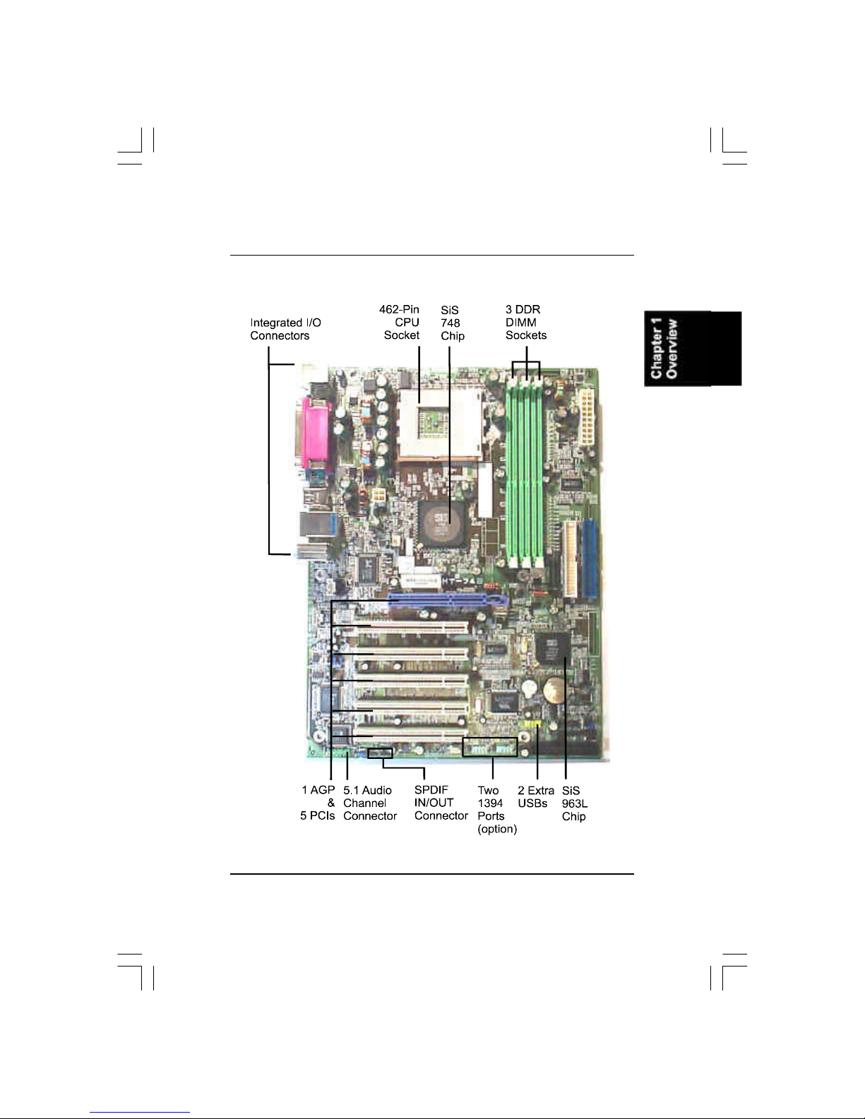
Theboardisbasedaround thehigh performance SiS748asNorthBridge
and SiS963/L (asSouthBridge.ItsAGP8XfunctionssupportedAGP3.0
interface and themostrobust3Dgameswithsoftwareenvironments.TheAGP
slotonboardsupports0.8/1.5voltAGPcard.
TheboardcomeswithaversatilerangeofI/Ofeaturessuchas2serialports,1
parallelport,1LAN,2optionalIEEE1394,1PS/2mouseandkeyboardconnec-
tor,6USBports,1mediaconnector(frontaudio,Line-in,Line-outand Mic-in).
Inaddition,theboardisequippedwith5.1audiochannelenhancedPCIbus
masterIDEconnectors.Ampleexpansionisavailablethrough5PCI*and1AGP
tomeettherequirementforenjoying theCPUbenefitsininternetapplicatons,
video/3Dgraphicsperformance,and soforth.
(*PCI1to4aremaster;PCI5slotisslave.)
OtherkeyfeaturesareRemoteOn/Off,AutoPowerFailureRecovery,inte-
gratedtemperaturemonitoring and systemfancontrol.Includedalsoislst
UtilitiesCDwithenhanceddriversand afewbundledsoft-waresolutions.

1-2
KT-748MainboardManual
NOTE:lstUtilities CD thatcontainspatchfiles,onboardvideo/au-
diochipdrivers,related online helpand otherusefulinformation
can be found inyourmainboardpackage.
Pleaseinstall itrightafteryourWindowsoperating systeminstalla-
tion isdone.PlaceyourlstUtilityinthe drive,an operating menu will
appearsinyourmonitor.PleaseselectAutoInstallation.It will auto-
maticallydetectwhichsoftwaretools(patchfiles,drivers)thatthe
mainboardneeds.Press OKbutton togo through the wholeinstal-
lation procedureinaverystraightforwardand easy way.It also
providesyou withacustomwaytoselectwanted patchfilesand
softwaredriversthatforonboardchipsuse.Thetop menu oflst
Utilities listsall thefunctionsthatallowedbythisboard.
PackageChecklist
If you discoverany itembelowwasdamagedorlost,pleasecontactyour
vendor.
1-3
Overview
TheKT-748 Mainboard

1-4
KT-748MainboardManual
MainFeatures
nCPU
nChipset
NorthBridge:SiS®748
SouthBridge:SiS®963L
n Memory
3memorysockets:
support184-pinPC2100/PC2700/PC3200DDRSDRAM
memorysize totallyupto3GHz
nExpansionSlots
1AGPSlot:Spec.3.04X/8X;5PCISlots
nIDEConnections
2IDEconnectors-PIOmode,UltraDMA66/100/133
up to4devices
nAudioFeatures
RealtekALC655controller;AC97Link
LINE_IN,LINE_OUT,MICROPHONE_INJack
5.1audiochannel; frontaudiopinheaders
nMountingHoles
6holes
nMainboardSize
12x9(unit:inch)
Duron:900-1.3GHzatFSB200MHz
Athlon :900-1.4GHzatFSB200/266MHz
Athlon XP:
PolominoCore:1500+-2100+atFSB266MHz
ThorughtbredCore:1700+-2600+atFSB266MHz
BartonCore:2500+-3000+atFSB333MHz
(Thosespeedexceedabovewerenottestyetwhenthisbook pressed.)

1-5
Overview
nI/OPorts
2IDEconnectors-
PIO,BusMaster,UltraDMA66/100/133
up to4devices
2serialportsCOM1and COM2
1parallelport
PS/2mouseand PS/2keyboard
6USB2.0ports
nLAN
RTL8100C/8110S®10/100/1000Ethernet
nIEEE 1394 Ports(optional)
VT6307L;2ports;1bracketwithcable
FICUniqueInnovation forUsers(NOVUS)-
EnhancedMainboardFeatures and SystemSupport
nLogoGenie
AuserfriendlyGUIsupporting Windows95/98SE(notWindows2000/
NT/ME/XP),LogoGenieallowsyou tocustomize,createorselectaLogo
whichwill bedisplayedwhenthesystemisbooting.
NOTE:
1.LogoGeniesupportsAwardBIOSonly.
2.If you createaLogo file(.bmp)byLogoGenie,the filesizemust
||||be 640 x464 x256 colors.
Toenablethisutility,pleaseproceedasfollows:
1.InsertsoftwareCD.SelectLogoGeniefromtheMenu
and followtheinstallation instructions.
2.AfterLogoGeniehasbeeninstalled,go toWindowsStartBox.
InProgramsMenu,selectLogoGenie,thenselectLogoGenie.
3.Press F1toreadHelpfiletounderstand howtousethissoftwareif
it isnewtoyou.

1-6
KT-748MainboardManual
NOTE:
Pleaseread Page 3-6fordetail information.
nEasyKey
Insteadofcompleting themulti-layeredBIOSsetup process these3Easy
Keyfunctionsprovidedirectaccess toSub-Menu whencompleting BIOS
settingsadjustments.
Easy-Keysareasfollows:
Ctrl+c:Toenterclocksettingsmenu.
Ctrl+p:ToloadPerformanceDefault settingsand restart.
Ctrl+f: ToloadFail-SafeDefault settingsand restart.
nBIOSGuardian
BIOSGuardianeffectivelyactsasafire-wall againstvirusesthatcanat-
tacktheBIOSwhilethesystemisrunning and by default isenabled.
WARNING:
BIOSGuardian mustbe disabled beforereflashBIOS.

2-1
Installation Procedures
Chapter2
Installation Procedures
Themainboardhasseveraluser-adjustablejumperson theboardthatallowyou to
configureyoursystemtosuit yourrequirements.Thischaptercontainsinformation
on thevariousjumpersettingson yourmainboard.
Tosetup yourcomputer,you mustcompletethefollowing steps:
Step1-Setsystemjumpers
Step2-Install memorymodules
Step3-Install theCentralProcessingUnit(CPU)
Step4-Install expansioncards
Step5-Connectribboncables,cabinetwires,and power supply
Step6-Setup BIOSsoftware
Step7-Install supportingsoftware tools
WARNING:Excessivetorque maydamage the mainboard.When
using an electricscrewdriveron the mainboard,makesurethat
the torque issettothe allowablerange of5.0~8.0kg/cm.
MainboardcomponentscontainverydelicateIntegrated Circuit
(IC)chips.Topreventstaticelectricityfromharming anyofthe
sensitivecomponents,you shouldfollowthe following precau-
tionswheneverworking on the computer:
1.Unplug the computerwhen working on the inside.
2.Holdcomponentsbythe edgesand trynottotouchthe IC
||||chips,leads,orcircuitry.
3.Wearan anti-staticwriststrap whichfitsaround the wrist.
4.Placecomponentson agrounded anti-staticpad oron the bag
thatcamewiththe componentwheneverthe componentsare
separated fromthe system.

2-2
KT-748MainboardManual
1).SetSystemJumpers
NOTE:Usersarenotencouraged tochange the jumper/switchset-
tingsnotlisted inthismanual.Changing the settingsimproperly
mayadverselyaffectsystemperformance.
ClearCMOS
TheCMOSRAMispoweredby theonboardbutton cell battery.To
cleartheRTCdata:
(1)Turnoff yourcomputer;
(2)openthesystemcase,disconnecttheATXpowercable;
(3)place thejumpercapontothepinpair2-3atleast6secondstoenable
CMOSclearance;
(4)place thejumpercapontothepinpair1-2todisabletheeffectof
CMOSclearance;
(5)connecttheATXpowercable;closethesystemcase;
(6)turnon yourcomputeruntil CMOSchecksumerrorappears;
(7)holddowntheDeletekeywhenboots;
(8)entertheBIOSSetup tore-enteruserpreferences.
1 2 3
1 2 3
Disable
(Default)
Enable
(Clear CMOS)

2-3
Installation Procedures
BIOSAnti-ReflashProtect
Thejumperhelpsuserstopreventthe64Kbootblocktablearea inthe
BIOSROMfrombeing overwrittenby mistake.
2).Install MemoryModules
1.LocateDDRDIMM socketson themainboard.

2-4
KT-748MainboardManual
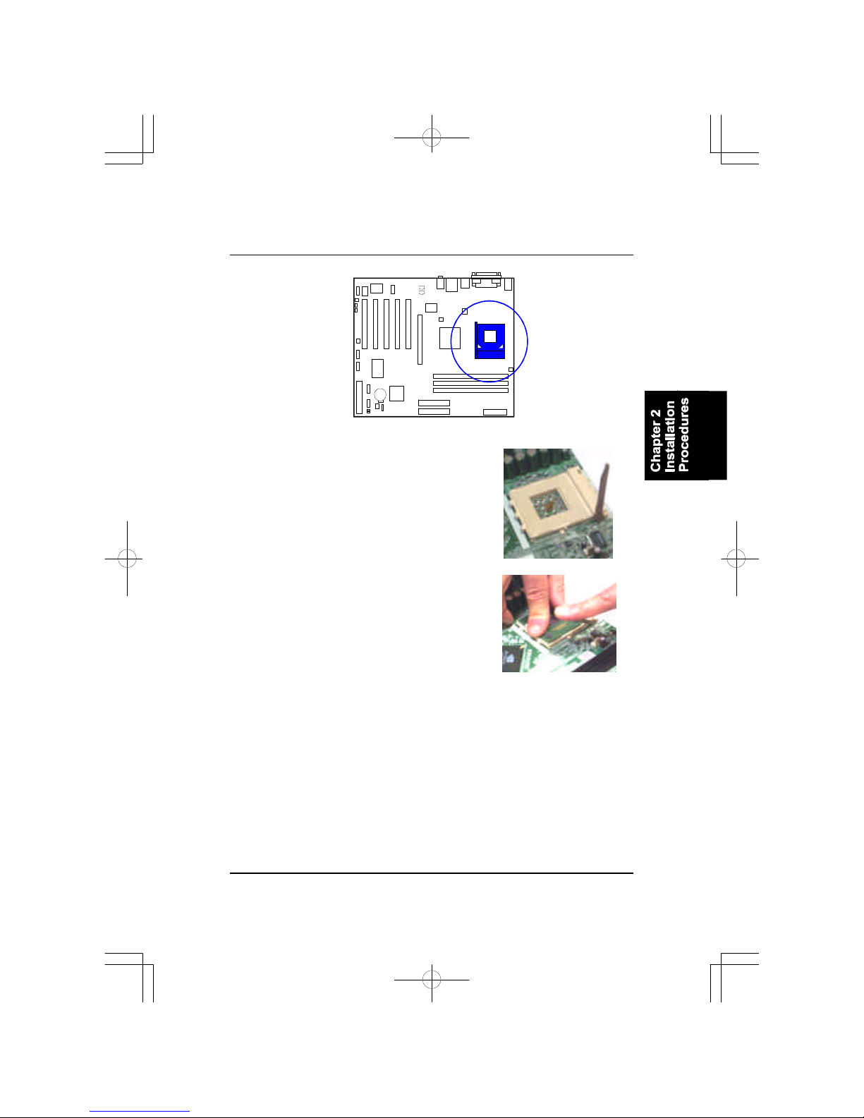
3).Install theCPU
Theproceduresbelowshowsyou howtoinstall yourCPUand itsfan
and heatsink.Firstofall,locatetheCPUsocketon thismainboard.
2.InstallDDRDIMM straightdown
intothesocket1using bothhands,
thensocket2,and soforth.
3.Theclipon bothendsofthe
socketwill closeup toholdthe
DDRDIMM inplace whentheDDR
DIMM reachesthesocketbottom.
CAUTION:
1.The heatsinkand fan you installed mustbe approved byAMD.
2.The mainboardmustbe placed on asolidplacetoavoidshaking
|||||whileinstall the heatsinkand fan on the board.
3.The heatsinkmustbe contactwiththe CPUtop tightly.
4.Neverrun the processorwithoutthe heatsinkproperlyand firmly
attached.PERMANENTDAMAGEWILLRESULT!
Themainboardhasbuilt-inSwitchingVoltageRegulatortosupportCPUVcore
autodetection.Thatis,Ithastheabilitytodetectand recognize theCPUvolt-
age,clock,ratioand enablesuserstosetup theCPUfrequencyfromtheBIOS
Setup Screen.Userscanadjustthefrequencythrough Frequency /Voltage
ControloftheBIOSSetup Screen.
2-5
Installation Procedures
1.Swing theleverupwordto90 degree.
2.Install theCPUand makesurethethepin1
orientation by aligning thesocketcornermarking
withthesocketcornerclosesttothelevertip.
DonotinserttheCPUby force.Makesurethe
processorisfullyinsertedintothesocketon all
sides.
Applysomethermalmaterials,suchaspasteor
tape,on theCPUtop;and install afanwith
heatsink thatapprovedby CPUmanufacturer
toavoidCPUdamage.Fordetail information,
pleaserefertotheCPUmanufacturerwebsite.

2-6
KT-748MainboardManual
3.Place thefanwithheatsink on theCPUtop
and press downtwoplasticclipstohook up
withtheholeson theretention moduleon two
sides.
4.Press downthewhitebaron eachclipto
fastenthefanseton theretention module.
AffixtheCPUby pressing theleverdownward
and locking it besidethesocket.
ConnectATXPower
The20-holepowerplug (top right)isconnected
totheATXpower20-pinpinheaders.The4-hole
12Vpowerplug (bottomright)isinsertedinthe
ATX_12Vpowerconnector.
Theplug fromthepowersupplywill onlyinsert
inoneorientation becauseofthedifferenthole
sizes.Find theproperorientation and pushdown
firmlymaking surethatthepinsarealigned.

2-7
Installation Procedures
CAUTION:
1.Makesuretounplug the powersupplywhen adding orremoving
expansion cardsorothersystemcomponents.Failuretodo so
maycauseseveredamage toboththe mainboardand expansion
cards.
2.Always observestaticelectricityprecautions.
3.Pleaseread Handling Precautionsatthe startofthismanual.
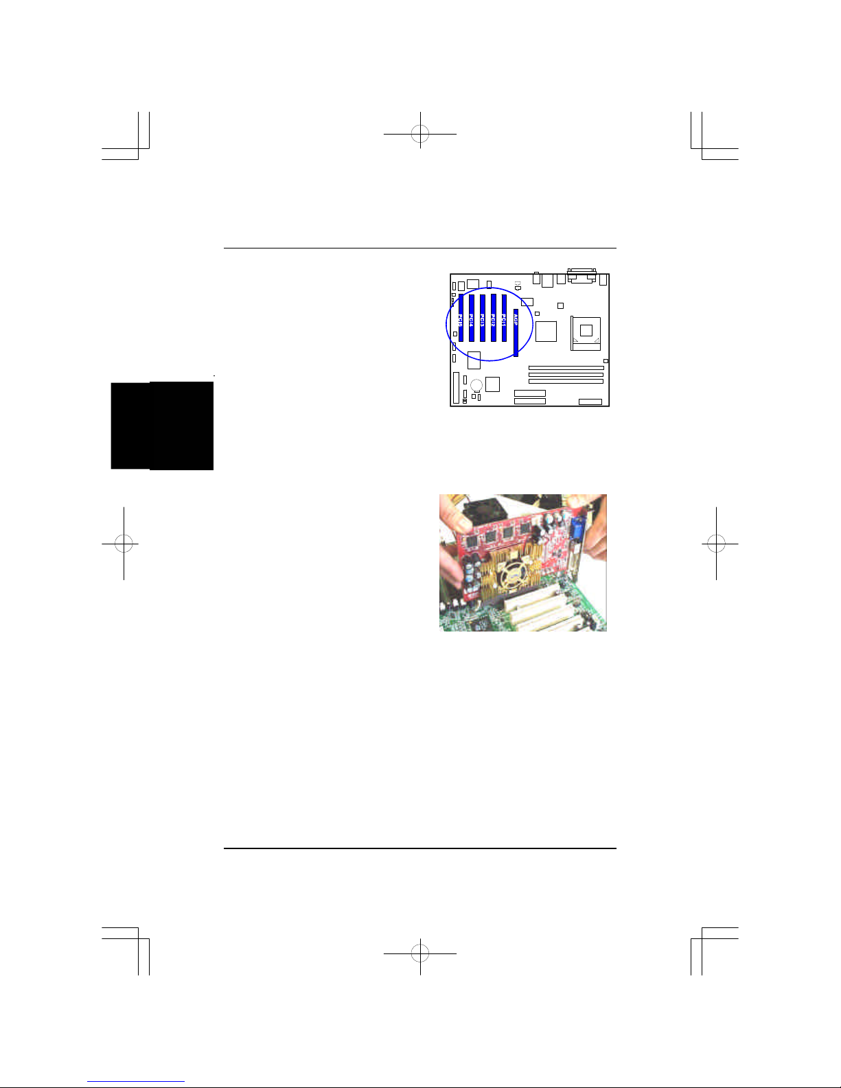
4).Install Expansion Cards
Thissection describeshowtoconnectanexpansion cardtooneofyour
systemexpansion slots.
Expansion cardsareprintedcircuit boardsthat,whenconnectedtothe
mainboard,increasethecapabilitiesofyoursystem.
Forexample,expansion cardscanprovidevideoand sound capabilities.The
mainboardfeaturesoneAGPand fivePCIbusexpansion slots.
NOTE:
1.Insertthe CPU(withfansinkand retention module)on
socket.
2.Connectthe 4-pinplug ofthe powersupply
3.Connectthe 20-pinplug ofthe powersupply.
Toremovethe processor,pleasedo itinreverseorder.
2-8
KT-748MainboardManual
1.Selectanavailableexpansion slot.
2.Removethecorresponding slotcoverfromthecomputerchassis.Un-
screwthemounting screwthatsecurestheslotcoverand pull theslotcover
outfromthecomputerchassis.Keeptheslotcovermounting screwnearby.
3.Pushthecardfirmlyintotheslot.
Pushdownon oneend oftheexpan-
sion card,thentheother.Usethisrock-
ing motion until themcardisfirmly
seatedinsidetheexpansion slot.Se-
curethecardwiththescrewremoved
inStep2.
2-9
Installation Procedures
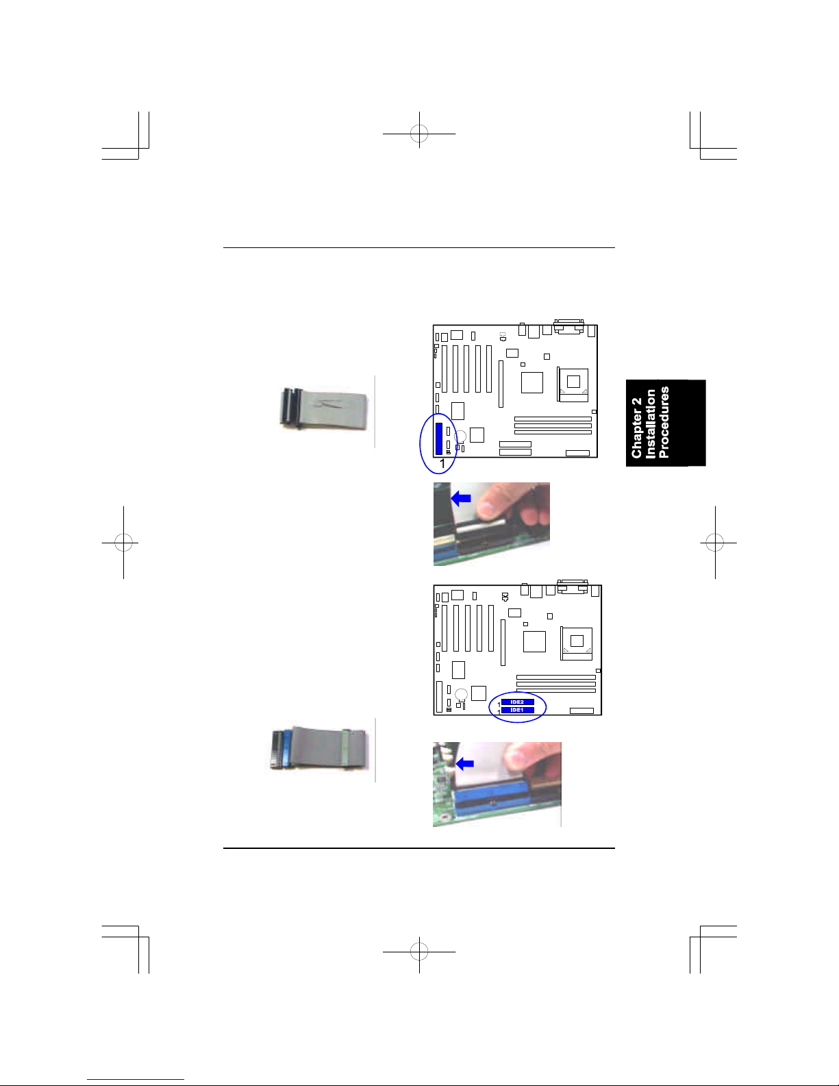
IDEDevice Connectors
Thetwoconnectors,PRIMARY
and SECONDARY,areusedfor
yourIDEharddiskdrives,CDdrives,
LS-120|drives,orIDEZIPdrives.
5).ConnectDevices
FloppyDisketteDrive Connector
Thisconnectorprovidestheconnection withyourfloppy diskdrive.
Insertthefloppy ribbon cable
(below)ontothefloppy connector.
Thecoloredstripe(indicatedby the
arrowhead,right)oftheribbon cable
mustbethesamesidewiththePin1.
Insertthefloppy ribbon cable
(below)ontothefloppy connector.
Thecoloredstripe(indicatedby the
arrowhead,right)oftheribbon cable
mustbethesamesidewiththePin1.

2-10
KT-748MainboardManual
PowerConnectors
The20-pinmaleblockconnectorisconnectedtotheATXpowersupply.The
4-pinmaleblockconnectorisfortheATX_12Vpoweruse.All twoconnectors
arelinkedwithyourATXpowersupply.Theplug fromthepowersupplywill
onlyinsertinoneorientation becauseofthedifferentholesizes.Find the
properorientation and pushdownfirmlymaking surethatthepinsarealigned.
FanConnectors
Thetwoconnectors,CPU_FAN,SYSTEM_FAN arelinkedtotheCPUfan,
casefan,respectively.CHIP_FAN canbeusedwithNorthBridgechipfan.
Table of contents
Other FIC Motherboard manuals


