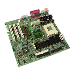
FIC VA-502 User manual

VA-502
MAINBOARD
MANUAL
DOC No. : 16059
Rev. : A3
Date : 9, 1997
Part No. : 25-10800-18

Handling Precautions
Warning :
1. Static electricity may cause damage to the integrated circuits on the
mainboard.
Before handling any mainboard outside of its protective packaging,
ensure that there is no static electric charge in your body.
2. There is a danger of explosion if the battery is incorrectly replaced.
Replace only with the same or an equivalent type recommended by the
manufacturer.
3. iscard used batteries according to the manufacturer’s instructions.
Observe the following basic precautions when handling the mainboard or other
computer components:
nWear a static wrist strap which fits around your wrist and is connected to a
natural earth ground.
nTouch a grounded or anti-static surface or a metal fixture such as a water
pipe.
nAvoid contacting the components on add-on cards, boards and modules and
with the “gold finger” connectors plugged into the expansion slot. t is
best to handle system components by their mounting bracket.
The above methods prevent static build-up and cause it to be discharged
properly.
Trademark
All trademarks mentioned in this manual are registered properly of the
respective owners.
Copyright
This manual may not, in whole or in part, be photocopied, reproduced,
transcribed, translated, or transmitted in whatsoever form without the written
the consent of the manufacturer, except for copies retained by the purchaser for
personal archival purposes.
Notice

Chapter 1 Overview
Package Checklist...................................................................................... 2
The VA-502 Mainboard............................................................................. 3
Main Features............................................................................................. 4
Ad anced Features..................................................................................... 6
Infrared (IR) Connections........................................................................... 7
Uni ersal Serial Bus (USB) Functionality.................................................. 8
Chapter 2 Installation Procedures
Mainboard Layout............................................................................. 10
1). Set System Jumpers............................................................................... 11
Jumpers............................................................................................. 11
Clear Password: CPW............................................................... 11
2). Install System Memory......................................................................... 12
DRAM and SDRAM......................................................................... 12
RAM Module Configuration............................................................. 13
Install SIMMs................................................................................... 14
Remo e SIMMs................................................................................ 14
Install DIMMs................................................................................... 15
Remo e DIMMs............................................................................... 15
Cache Memory.................................................................................. 16
3). Install the CPU...................................................................................... 17
CPU External Clock (Bus) Frequency: CLK1, CLK2, CLK3... 18
CPU to Bus Frequency Ratio: FREQ1, FREQ2, FREQ3.......... 18
Intel Pentium/ Pentium MMX CPUs......................................... 19
Frequency............................................................................. 19
Voltage................................................................................. 20
AMD-K5/K6 CPUs................................................................... 21
Frequency............................................................................. 21
Voltage................................................................................. 22
Cyrix 6x86/MX CPUs............................................................... 23
Frequency............................................................................. 23
Voltage................................................................................. 24
IBM 6x86/MX CPUs................................................................ 25
Frequency............................................................................. 25
Voltage................................................................................. 26
4). Install Expansion Cards......................................................................... 27
5). Connector Cables and Power Supply.................................................... 29
AT Keyboard Connector: AT_KB............................................ 29
Serial Port Connectors: COM1, COM2..................................... 29
CPU Fan Connector: FAN........................................................ 30
Floppy Diskette Dri e Connector: FLOPPY............................. 30
i
Table of Contents

VA-502 Mainboard Manual
Infrared Connector: IR.............................................................. 31
PS/2 Mouse Connector: MS_CON............................................ 31
Front Panel Block Connector: F_PNL...................................... 32
Standard Power Connector: POWER........................................ 33
IDE HDD De ice Connectors: PRIMARY, SECONDARY..... 34
Printer Connector: PRINTER.................................................... 34
Uni ersal Serial Bus Connectors: USB1, USB2........................ 35
Chapter 3 Award BIOS Setup
CMOS Setup Utility................................................................................... 37
Standard CMOS Setup............................................................................... 38
Hard Disk Configurations................................................................. 38
BIOS Features Setup.................................................................................. 40
Chipset Features Setup............................................................................... 43
Power Management Setup.......................................................................... 47
PCI Configuration Setup............................................................................ 50
PnP Configuration Setup............................................................................ 52
Load BIOS Defaults................................................................................... 53
Load Setup Defaults................................................................................... 53
Super isor/User Password.......................................................................... 53
IDE HDD Auto Detection.......................................................................... 54
Sa e and Exit Setup.................................................................................... 55
Exit without Sa ing.................................................................................... 55
Appendix A BIOS Update Instruction
Flash Process.............................................................................................. 57
Appendix B Software Utilities
DMI Utility................................................................................................ 59
Starting DMI Utility.......................................................................... 59
Appendix C Application Note
................................................................................................................... 60
ii

Overview
Based on the new highly-integrated VIA 580VPX, the mainboard combines
blistering PentiumÒ processor per ormance with support or intelligent
diagnostic and power management eatures to provide a power ul and versatile
plat orm.
With its switching voltage regulator, the VA-502 runs a complete range o Intel
PentiumÒ processors, including the Intel Pentium processor with MMXÔ
technology, as well as the AMD-K5Ô and Cyrix/IBM 6x86Ô, and is easily
upgradable to the Cyrix/IBM MXÔ and the AMD-K6Ô. For added power and
per ormance, the VA-502 takes up to 512KB Pipeline Burst Level II cache and
up to 512MB DRAM via our 72-pin SIMM sockets and two 168-pin DIMM
sockets which accept high-speed EDO, and lightning- ast SDRAM memory
types.
The VA-502 comes with a ull set o I/O eatures conveniently integrated on the
rear I/O panel, including two USB connectors. The board also has an integrated
PCI Bus Master Enhanced IDE controller with support or the new Ultra
DMA/33 protocol, which doubles ATA-2 Hard Disk Drive data trans er rates to
33MB/s while maintaining ull backwards compatibility with existing PIO Mode
3, PIO Mode 4 and DMA Mode 2 devices.
Chapter 1 o this manual gives you a brie overview o the VA-502 mainboard,
including its main components and eatures. Chapter 2 contains advice on how
to upgrade and install key components on the mainboard, while Chapter 3
provides detailed in ormation about the board’s BIOS settings. For the most up-
to-date in ormation about your mainboard and the latest FAQs and BIOS
updates, visit FIC Online at www. ic.com.tw.
1
Chapter 1

VA-502 Mainboard Manual
Package Checklist
Please check that your package contains all the items listed below. I you
discover any item is damaged or missing, please contact your vendor.
nThe VA-502 mainboard
n
nThis user manual
n
nOne IDE HDD cable
n
nOne flopp disk drive cable
n
nOne printer and COM1 cable
n
nOne COM2 cable
n
nSoftware utilit
n
nOne USB riser card (optional)
2

Overview
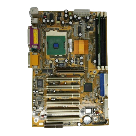
The VA-502 Mainboard
3

VA-502 Mainboard Manual
Main Features
The VA-502 mainboard comes with the ollowing high-per ormance eatures:
nEasy Installation
n Award BIOS with support for Plug and Play, auto detection of Hard
Drive
n and IDE features, and MS indows 95 compatible.
nFlexible Processor Support
Onboard 321-pin ZIF socket and switching voltage regulator support
|||||||||complete range o leading-edge processors:
Intel PentiumÒ P55C with MMXÔ technology 166/200/233 MHz
processors.
Intel PentiumÒ P54C/P54CS 90/100/120/133/150/166/200 MHz
processors.
|||||||||AMD-K6Ô-166 (166 MHz) / K6-200 (200 MHz) / K6-233 (233 MHz)
|||||||| processors.
|||||||||AMD-K5Ô- PR90 (90 MHz) / K5-PR100 (100 MHz) / K5-PR120 (90
|||||||||MHz) / K5-PR133 (100 MHz) / K5-PR150 (105 MHz) / K5-PR166 (116
|||||||||MHz) / K5-PR200 (133 MHz) processors.
||||||||Cyrix 6x86MXÔ- PR166 (150 MHz) / 6x86MX-PR200 (166 MHz) / 6x86-
|||||||||MX-PR233 (200 MHz) / 6x86MX-PR266 (233 MHz) processors. Please
|||||||||read page 23 or details.
|| || | Cyrix 6x86Ô- PR133+ (110 MHz) / 6x86-PR150+ (120 MHz) / 6x86-
|||||||||PR166+ (133 MHz) / 6x86-PR200+ (150 MHz) processors.
|||||||||IBM 6x86MXÔ- PR166 (150 MHz) / 6x86MX-PR200 (166 MHz) / 6x86-
|||||||||MX-PR233 (200 MHz) / 6x86MX-PR266 (233 MHz) processors. Please
|||||||||read page 25 or details.
||||||||IBM 6x86Ô- PR133+ (110 MHz) / 6x86-PR150+ (120 MHz) / 6x86- |||||||||
PR166+ (133 MHz) processors. |
| || || | |
nLeading Edge Chipset
n VIA 580VPX chipset, including a CPU interface controller, advanced
n cache controller, integrated DRAM controller, synchronous ISA bus
n controller, PCI local bus interface, integrated power management unit.
nUltra-fast Level II Cache
Supports onboard 256KB/512KB synchronous PBSRAM direct-mapped
writ||write-back cache memory.
4

Overview
nVersatile Main Memory Support
n Accepts up to 512MB RAM in two banks using four SIMMs of 8, 16,
32,
n 64, 128MB with support for FPM and EDO DRAM and two DIMMs
of 8,
n 16, 32, 64MB with support for SDRAM and EDO DRAM.
nISA & PCI Expansion Slots
n Three 16-bit ISA and four 32-bit PCI expansion slots provide all the
room
n you need to install a full range of add-on cards.
n
nUSB Support
n Two USB ports on an optional riser card allow convenient, high-speed
Plug |||||||||and Play connections to the growing number of USB compliant
external |||||||||peripheral devices on the market.
n
nEnhanced PCI Bus Master IDE Controller
n Integrated Enhanced PCI local bus IDE controller with two connectors
n supports up to four IDE devices such as Hard Disk, CD-ROM or Tape
Backup drives via two channels or high speed data throughput. This
controller supports PIO Modes 3 and 4, and DMA Mode 2 or optimized
system per ormance.
nSuper Multi I/O
n Integrated SMC FDC 37C669/UMC UM8669F chipset features two
||||||||16550A UART compatible serial ports, one EPP/ECP capable parallel
port, ||||||||one IR port, and one Floppy Disk Drive connector.
5

VA-502 Mainboard Manual
Advanced Features
This mainboard comes equipped with the most advanced new eatures that not
only optimize the per ormance o the latest processors but also enhance the
manageability, power management capabilities, and user- riendliness o your
system. This section provides detailed in ormation on these eatures, and how
they are implemented on the mainboard.
nOptimized Intel MMXÔ Performance
The mainboard utilizes the advanced eatures o the VIA 580VPX to
optimize the unrivaled per ormance o the Intel PentiumÒ processor with
MMXÔ technology, allowing you to enjoy a richer video, audio, digital
imaging and communications experience rom the latest generation o
multimedia so tware. To provide you with additional lexibility, the
mainboard also supports other leading-edge processors eaturing Intel’s
MMXÔ technology, including the AMD-K6Ô processor.
nLightning-Fast SDRAM Performance
The mainboard supports the new generation o lightning- ast SDRAM
(Synchronous Dynamic Random Access Memory) via its two onboard 168-
pin DIMM sockets. SDRAM delivers an added boost to overall system
per ormance by increasing the CPU-to-memory data trans er rate to
528MB/sec compared to 264MB/sec or conventional EDO DRAM.
SDRAM per ormance on the VA-502 is urther boosted by the board’s
integrated I2C controller, which optimizes the memory timing settings.
nBlistering Ultra DMA/33 HDD Performance
With its integrated Enhanced PCI Bus Master IDE controller that supports
the new Ultra DMA/33 protocol, this mainboard doubles HDD data trans er
rates to 33MB/sec, compared to 16MB/sec or conventional PIO Mode 3,
PIO Mode 4, and DMA Mode 2 devices. By reducing the CPU’s workload
and increasing CPU utilization, Ultra DMA/33 signi icantly improves
system per ormance when running applications under WindowsÒ 95 and
WindowsÒ NT environments. The Ultra DMA/33 protocol is completely
backward compatible with conventional ATA-2 HDD devices; so the
mainboard also supports existing PIO Mode 3, PIO Mode 4 and DMA
Mode 2 devices using the same cable.
6

Overview
With the integrated Enhanced PCI Bus Master IDE controller you can
connect up to our Enhanced IDE peripheral devices to your system. All
devices are categorized in the same way that IDE hard disks were
con igured in the past, with one device set as the master device and the
other as the slave device. We recommend that Hard Disk Drives use the
primary IDE connector and that CD-ROM Drives utilize the secondary IDE
connector or optimum system per ormance.
nfrared ( R) Connections
This mainboard eatures support or highly-sophisticated SIR technology, which
allows bi-directional and cordless data transactions with other IrDA compliant
computers and peripheral devices using in rared as a medium. This transmission
is carried out in either Full Duplex Mode or Hal Duplex Mode. The ormer
allows simultaneous data transmission and reception, while the latter disables
the reception when transmission occurs.
The I/O chipset on this mainboard eatures a SIR inter ace that is ully
compliant with the IrDA standard. An IrDA device can be installed via a 9-pin
D-type connector in the rear panel o the computer which is linked by a cable
to the onboard IrDA pinhead.
The serial port COM2 on this mainboard is designed to be a SIR compliant
port. I you wish to install the SIR connection eature, you need to adjust the
BIOS option or high-speed per ormance.
7

VA-502 Mainboard Manual
Universal Serial Bus (USB) Functionality
This mainboard eatures integrated support or state-o -the-art USB technology,
which provides high-speed and easy-to-use Plug & Play connections to the
uture generation o external peripherals, such as keyboards, mouse, monitors,
game devices, scanners, printers, and ax/modems.
USB overcomes conventional I/O bottlenecks by combining the I/O ports into a
single dual-channel connector. For optimum ease o use and lexibility, USB not
only allows the automatic detection and con iguration o peripherals a ter
installation, but also enables the simultaneous connection.
This mainboard eatures an optional USB riser card (see the photo below) with
bracket that can be installed in one o the I/O expansion slots on the rear panel
o the system, as shown in the illustration below. It provides ast and convenient
Plug and Play peripheral connections outside your computer, allowing you take
ull advantage o the universal unctionality and lexibility o USB technology.
8

Installation Procedures
!"
nStep 1 -
nSet system jumpers
n
nStep 2 -
nInstall System Memory
n
nStep 3 -
n| Install the CPU
nStep 4 -
n | Install expansion cards
nStep -
n | Connect cables and power supply
n
nStep 6 -
n Set up BIOS feature (Please read Chapter Three.)
n
CAUTION : If you use an electric drill to install this mainboard on your
chassis, please wear a static wrist strap. The recommended electric drill
torque is from .0 to 8.0 kg/cm to avoid damaging chips’ pins.
n
9
Chapter 2

VA- 02 Mainboard Manual
Mainboard Layout
10

Installation Procedures
1). Set System umpers
Jumpers
# $
!%
%
"
NOTE : Users are not encouraged to change the jumper settings not listed in
this manual. Changing the jumper settings improperly may adversely affect
system performance.
Clear Password: CPW
&
' (
11

VA- 02 Mainboard Manual
12

Installation Procedures
2). Install System Memory
DRAM and SDRAM
%)*+)*,
)* -
!%!
. )* / $
0 * * +$0**, 123 ' 0 *
*+'0**, &$0**%413*567*+6
7*,&'8+&9'8,')* &'0**
%24*5&'8')*$')*
$')*
:
% %!
$')*
:!
$')*
5%')*
)* 09)*
13

VA- 02 Mainboard Manual
RAM Module Configuration
(Unit : MB)
TOTAL
MEMORY
SIMM 1 & 2
(Bank 0)
SIMM 3 & 4
(Bank 1)
DIM1
(Bank 2)
DIM2
(Bank 0)
8 4 & 4
8
16 8 & 8
4 & 4 4 & 4
16
32 16 & 16
8 & 8 8 & 8
32
64 32 & 32
16 & 16 16 & 16
64*
128 64 & 64
32 & 32 32 & 32
64* 64*
2 6 64 & 64 64 & 64
128* & 128*
12 128* & 128* 128* & 128*
NOTE :
1. * A RAM module of this size was not available for testing at press time.
2. DIM1 and DIM2 only support 3.3V (unbuffered) EDO and SDRAM |||||
modules. It is recommended that SIMMs and DIMMs are not
installed at the same time on this mainboard to avoid unexpected
failure.
3. The different size of DIM1 and DIM2 is allowed. For example, 16MB is
installed on DIM1 socket, 32MB is installed on DIM2 socket. DIM2
and SIMM 1&2 are shared. That is, It is not allowed to install RAM
modules on DIM2 and SIMM 1 &2 at the same time. This mainboard
allows the SIMMs (without ECC or parity check support) which
14

Installation Procedures
latency time are 70ns, 60ns, 0ns; and for the DIMMs which latency
time are 12ns, 10ns.
1

VA- 02 Mainboard Manual
Install SIMMs
;$0**"
CAUTION : Always turn the system power off before installing or removing
any device; and see “Handling Precautions” at the start of this manual.
1 <$0** +$ ,
NOTE : SIMMs in each bank must be of the same type; and the BIOS
automatically configures the memory size.
;$0**4%
$0**
16
Table of contents
Other FIC Motherboard manuals