FIC PA-2005 User manual

PA-2005
MAINBOARD
MANUAL
DOC No. : 15319
Rev. : B2
Date : 1/1997
Part No. : NA

Handling Precautions
Warning :
1. Static electricity may cause damage to the integrated circuits on the
mainboard.
Before handling any mainboard outside of its protective packaging,
ensure that there is no static electric charge in your body.
2. There is a danger of explosion if the battery is incorrectly replaced.
Replace only with the same or an equivalent type recommended by the
manufacturer.
3. Discard used batteries according to the manufacturer’s instructions.
Observe the following basic precautions when handling the mainboard or other
computer components:
■Wear a static wrist strap which fits around your wrist and is connected to a
natural earth ground.
■Touch a grounded or anti-static surface or a metal fixture such as a water
pipe.
■Avoid contacting the components on add-on cards, boards and modules
and with the “gold finger” connectors plugged into the expansion slot. It is
best to handle system components by their mounting bracket.
The above methods prevent static build-up and cause it to be discharged
properly.
Trademark
All trademarks mentioned in this manual are registered properly of the respective owners.
Copyright
This manual may not, in whole or in part, be photocopied, reproduced, transcribed,
translated, or transmitted in whatsoever form without the written the consent of the
manufacturer,except for copies retainedby the purchaser for personal archival purposes.
Notice

i
Chapter 1 Overview
Main Features........................................................................................ 2
Package Checklist.................................................................................. 4
The PA-2005 Mainboard............................................................... 5
The Cables.................................................................................... 6
This User Manual ......................................................................... 7
Something Interesting............................................................................. 8
The BIOS Setup Utility................................................................. 8
IRQ Functionality.......................................................................... 9
DMA Channels of ISA Cards ........................................................ 10
Enhanced IDE............................................................................... 10
Serial Infrared (SIR) Connections.................................................. 11
Universal Serial Bus (USB) Functionality..................................... 12
Chapter 2 Installation Procedures
Mainboard Layout.................................................................................. 14
1). Set System Jumpers.......................................................................... 15
Jumpers ........................................................................................ 15
Clear Password: CPW............................................................ 16
Flash EPROM Type Selection: MFG5.................................... 16
PS/2 Mouse Feature: MS_1 and MS_2 (optional)................... 17
PCI2 ID: PCI2ID.................................................................... 17
2). Install RAM Modules........................................................................ 18
DRAM Memory............................................................................ 18
RAM Module Configuration.......................................................... 19
Install SIMMs............................................................................... 20
Remove SIMMs............................................................................ 21
Cache Memory.............................................................................. 22
256KB Cache SRAM.................................................................... 22
512KB Cache SRAM.................................................................... 23
1MB Cache SRAM ....................................................................... 24
3). Install the CPUs................................................................................ 25
CPU External Clock (Bus) Frequency:
CLK1, CLK2, CLK3.............................................................. 27
Table of Contents

PA-2005 Mainboard Manual
ii
CPU to Bus Frequency Ratio: FREQ1, FREQ2....................... 28
Intel Pentium CPUs............................................................... 29
Frequency......................................................................... 29
Voltage............................................................................. 30
AMD-K5/K6 CPUs................................................................ 31
Frequency......................................................................... 31
Voltage............................................................................. 32
Cyrix 6x86/MX CPUs ........................................................... 33
Frequency......................................................................... 33
Voltage............................................................................. 34
IBM 6x86/MX CPUs............................................................. 35
Frequency......................................................................... 35
Voltage............................................................................. 36
Installation of Cyrix (or IBM) 6x86 CPU Fan......................... 37
4). Install Expansion Cards .................................................................... 38
5). Connect Cables and Power Supply.................................................... 40
Keyboard Connector: AT_KB ................................................ 40
Serial Port Connectors: COM1 and COM2............................. 40
CPU Fan Connectors: FAN.................................................... 41
FloppyDiskette Drive Connector:FLOPPY........................... 41
Front Panel Block Connector: F_PNL .................................... 42
IDE HDD Device Connectors:
PRIMARY and SECONDARY .............................................. 43
Infrared Connector: IR ........................................................... 43
Outlet Connector: OUTLET................................................... 44
PS/2 Mouse Connector: MS_CON......................................... 44
Power Connector: POWER .................................................... 45
Printer Block Connector: PRINTER....................................... 45
Remote Power Connector: RPW_CON................................... 46
Universal Serial Bus Connector: USB1 and USB2
(Reserved For Future Upgrade).............................................. 46
Chapter 3 Award BIOS Setup
CMOS Setup Utility............................................................................... 47
Standard CMOS Setup........................................................................... 48
BIOS Features Setup.............................................................................. 50

Installation Procedures
iii
Chipset Features Setup........................................................................... 53
Power Management Setup...................................................................... 57
PCI Configuration Setup......................................................................... 60
PnP Configuration Setup........................................................................ 62
Load BIOS Defaults............................................................................... 63
Load Setup Defaults............................................................................... 63
Supervisor/User Password...................................................................... 63
IDE HDD Auto Detection....................................................................... 64
Save and Exit Setup............................................................................... 65
Exit without Saving................................................................................ 65
Appendix A Application Note

PA-2005 Mainboard Manual
iv
This Page Intentionally Left Blank

1
Overview
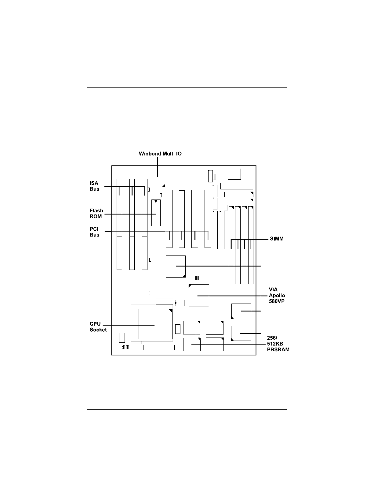
The PA-2005 mainboard combines the advanced capabilities of the VIA
Apollo 580VP® chipset with a high-performance concurrent PCI local bus
architecture to provide the ideal platform for unleashing the unsurpassed speed
and power of the Intel Pentium® processor.
This highly-flexible mainboard is designed to run a full range of Intel
Pentium™, Cyrix 6x86/MX™, IBM 6x86/MX™ and AMD-K5/K6™
processors; and can be easily upgraded using its 321-pin ZIF socket. The
processor's advanced performance is complemented by a second level write
back Pipeline Burst SRAM cache of up to 1MB and main memory of up to
512MB RAM. The main memory is installed using the board's four 72-pin
SIMM sockets that accept an unrivaled choice of high-speed EDO, ultra-fast
Burst EDO, or standard Fast Page Mode DRAM.
The PA-2005 integrates a full set of I/O features onboard, including two 16550
UART compatible serial ports, one EPP/ECP capable parallel port, and one
Floppy Disk Drive controller. It also comes with a built-in Enhanced IDE
controller that provides convenient, high-speed PCI Bus Master connections
with up to four IDE devices, including Hard Disk and CD-ROM drives. Three
16-bit ISA slots and four 32-bit PCI slots provide ample room for further
expansion. The mainboard also features support for the state-of-the-art
Universal Serial Bus (USB) that provides ease-of-use and high-speed Plug &
Play connections to future USB compliant peripheral devices. The IrDA
compliant serial port and optional onboard SIR support further enhance system
I/O connectivity.
This chapter gives you a brief overview of the PA-2005 mainboard. In addition
to basic information on the board's main components and features, it also
provides advice on how to upgrade and expand it. For updated BIOS, drivers,
or product release information, please visit FIC's home page at:
http://www.fic.com.tw.
Congratulations on your decision to adopt the PA-2005 mainboard. With its
high-speed PCI local bus architecture and ultra-fast I/O connections, the PA-
2005 provides the ultimate solution for optimizing the performance of your
high-end system.
Chapter 1

PA-2005 Mainboard Manual
2
Main Features
The PA-2005 mainboard comes with the following high-performance features:
■Easy Installation
Award BIOS with support for Plug and Play, auto detection of Hard Drive
and IDE features, and MS Windows 95®.
■Flexible Processor Support
The onboard 321-pin ZIF socket supports Intel Pentium (P54C) CPU speed
75/90/100/120/133/150/166/200 MHz processors / P54CTB / P55C.
Cyrix 6x86-P120+ (100 MHz) / 6x86-P133+ (110 MHz) / 6x86-P150+
(120 MHz) / 6x86-P166+ (133 MHz) / 6x86-P200+ (150 MHz)* proc/
\\\\\\/ MX series processors.
IBM 6x86-P120+ (100 MHz) / 6x86-P133+ (110 MHz) / 6x86-P150+
(120 MHz) / 6x86-P166+ (133 MHz) / 6x86-P200+ (150 MHz)* / M2 seri|
proc/ MX series processors.
AMD K5-PR75 (75 MHz) / K5-PR90 (90 MHz) / K5-PR100 (100 MHz) /
K5-PR120 (90 MHz) / K5-PR133 (100 MHz) / K5-PR150 (105 MHz) /
K5-PR166 (116 MHz) / K5-PR200 (133 MHz) / K6-166/200 processors.
NOTE : * The support for Cyrix 6x86-P200+ and IBM 6x86-P200+ is optional.
■Leading Edge Chipset
Intel Apollo 580VP chipset, including a CPU interface controller,
advanced
cache controller, integrated DRAM controller, synchronous ISA bus
controller, PCI local bus interface, integrated power management unit.
■Ultra-fast Level II Cache
Supports up to 256KB/512KB/1MB synchronous PBSRAM direct-mapped
writwrite-back cache memory.
■Versatile Main Memory Support
Accepts up to 512MB RAM in two banks using 72-pin SIMMs of 4, 8,
16, 32, 64, 128MB with support for EDO, BEDO, and Fast Page Mode
me..memory.
■ISA & PCI Expansion Slots
Three 16-bit ISA and four 32-bit PCI expansion slots provide all the room
you need to install a full range of add-on cards.

Overview
3
■USB Support (reserved for furture upgrade)
Onboard support for two Universal Serial Bus connectors via a plug-in
con||connector.
■Enhanced PCI Bus Master IDE Controller
Integrated Enhanced PCI local bus IDE controller with two connectors
supports up to four IDE devices such as Hard Disk, CD-ROM or Tape
Backup drives via two channels for high speed data throughput. This
controller supports PIO Modes 3 and 4, and DMA Mode 2 for optimized
system performance.
■Super Multi I/O
Integrated Winbond W83877F or W83877AF I/O chipset features two
165.16550A UART compatible serial ports, one EPP/ECP capable parallel port,
one one IR port, and one floppy disk drive connector.

PA-2005 Mainboard Manual
4
Package Checklist
Please check that your package contains all the items listed below. If you
discover any item is damaged or missing, please contact your vendor.
■The PA-2005 mainboard
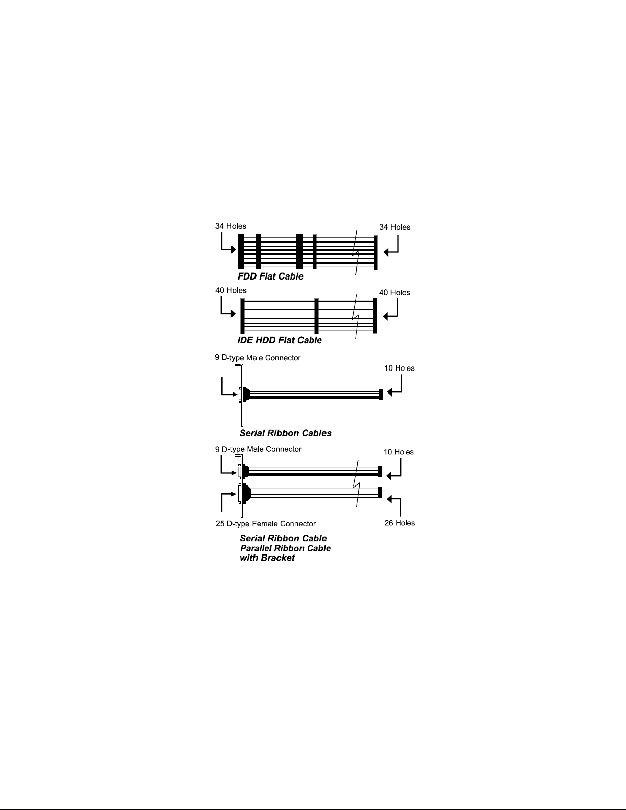
■One serial port and parallel port cable with bracket
■One serial port cable with bracket
■One IDE device cable
■One floppy disk drive cable
■One SIR cable (optional)
■This user manual
■PS/2 mouse cable with bracket (optional)
Overview
5
The PA-2005 Mainboard
PA-2005 Mainboard Manual
6
The Cables

Overview
7
This User Manual
This manual is designed to guide you and facilitate your use of the PA-2005
mainboard. It contains a description of the design and features of the
mainboard, and also includes useful information for changing the configuration
of the board and the system it is installed in. The manual is divided into three
chapters:
■Chapter 1 - Overview
gives an overview of the mainboard and describes its major components
and features.
■Chapter 2 - Installation Procedures
gives instructions on how to set up the mainboard, including jumper
settings and CPU installation guides.
■Chapter 3 - Award BIOS Setup
briefly explains the mainboard’s BIOS system setup in general and tells
you
how to run it and change the system configuration settings.
■Appendix
provides application tips that help the mainboard to archieve its best
perf|performance.
NOTE : The material in this manual is for information only and is subject to
change without notice. We reserve the right to make changes in the product
design without reservation and without notification to its users. We shall not be
liable for technical or editorial omissions made herein; nor for incidental or
consequential damages resulting from the furnishing, performance, or use of
this material.

PA-2005 Mainboard Manual
8
Something Interesting
This section provides useful information that you will need to know should you
decide to modify or upgrade the configuration of the mainboard and the system
it is installed in. If you do not have the confidence to upgrade the mainboard
yourself, we advise that you consult a qualified service technician for
assistance.
The BIOS Setup Utility
The BIOS (Basic Input Output System) is the basic firmware that instructs the
computer how to operate. For the BIOS to work properly, there must be a
record of the computer’s hardware and configuration settings for it to refer to.
This record is created using the Setup Utility, a program that is stored
permanently in the BIOS ROM chip on the mainboard.
The system configuration record created by the Setup Utility is also stored on
the mainboard, but not permanently. This section of the memory is stored in
the NVRAM.
When you buy your computer, the system configuration record will already be
set and may in some cases differ from the basic defaults. The first time you use
your computer or when you need to re-configure your system, you should run
the Setup Utility and write down the settings.

Overview
9
IRQ Functionality
As you read through this manual, you will see the term IRQ on a number of
occasions. It is important for you to know what this term means, particularly if
you intend to upgrade your system.
IRQ stands for Interrupt Request, the process in which an input or output
device tells the processor to temporarily interrupt its current task and
immediately process something from the source of the interrupt. When it has
completed this, the processor returns to the task it was already processing.
Devices that need an IRQ line to operate sometimes need to have exclusive use
of that line.
A large number of add-on cards, such as sound cards and LAN cards, require
the use of an IRQ line to function. Some of IRQs may already be in use by
components in the system such as the keyboard and mouse. Add-on cards that
need to use an IRQ draw from the unused group of IRQs. When installing a
card that uses an IRQ, it will have a default IRQ setting which you might have
to change if that IRQ is already in use and cannot be shared.
Both ISA and PCI add-on cards may need to use IRQs. System IRQs are
available to add-on cards installed on the ISA bus first; the remaining ones can
be used by cards installed on the PCI bus. There are two categories of ISA add-
on cards: so-called Legacy ISA cards, which need to be configured manually
and then installed in any available ISA slot; and Plug and Play (PnP) ISA
cards, which are configured automatically by the system. As a result, when you
install Legacy ISA cards, you have to carefully configure the system to ensure
that the installed cards do not conflict with each other by having the same IRQ.
With PnP cards, on the other hand, IRQs are assigned automatically from the
ones available in the system. In the case of PCI add-on cards, the BIOS
automatically assigns an IRQ card to the PCI slot the card is installed in.

PA-2005 Mainboard Manual
10
DMA Channels of ISA Cards
Some Legacy and PnP ISA add-on cards may also need to use a Direct
Memory Access (DMA) channel. DMA assignments for this mainboard are
handled in the same way as the IRQ assignment process outlined above. For
more information, please refer to Chapter 3 of this manual.
Enhanced IDE
This mainboard features an integrated Enhanced IDE controller that provides
convenient, high-speed connections with up to four IDE devices, such as Hard
Disk, CD-ROM and Tape Backup Drives. Enhanced IDE is an upgrade of the
original IDE specification and provides increased capabilities and performance
in a number of areas, including support for Hard Disk Drives utilizing the PIO
Mode 4 timing scheme.
With the integrated IDE controller you can connect up to four IDE peripheral
devices to your system. All devices are categorized in the same way that IDE
Hard Disks were configured in the past, with one device set as the Master
device and the other as the Slave device. We recommend that Hard Disk
Drives use the Primary IDE connector and that CD-ROM drives utilize the
Secondary IDE connector for improved system performance.

Overview
11
Serial Infrared (SIR) Connections
This mainboard features support for highly-sophisticated SIR technology,
which allows bi-directional and cordless data transactions with other IrDA
compliant computers and peripheral devices using infrared as a medium. This
transmission is carried out in either Full Duplex Mode or Half Duplex Mode.
The former allows simultaneous data transmission and reception, while the
latter disables the reception when transmission occurs.
The I/O chipset on this mainboard features a SIR interface that is fully
compliant with the IrDA standard. An IrDA device can be installed via a 9-pin
D-type connector in the rear panel of the computer which is linked by a cable
to the onboard IrDA pinhead, as shown in the illustration below.
The serial port COM2 on this mainboard is designed to be a SIR compliant
port. If you wish to install the SIR connection feature, you need to adjust the
BIOS option for high-speed performance.
PA-2005 Mainboard Manual
12
Universal Serial Bus (USB) Functionality
This mainboard features integrated support for state-of-the-art USB
technology, which provides high-speed and easy-to-use Plug & Play
connections to the future generation of external peripherals, such as keyboards,
mouse, monitors, game devices, scanners, printers, and fax/modems.
USB overcomes conventional I/O bottlenecks by combining the I/O ports into
a single dual-channel connector. For optimum ease of use and flexibility, USB
not only allows the automatic detection and configuration of peripherals after
installation, but also enables the simultaneous connection.
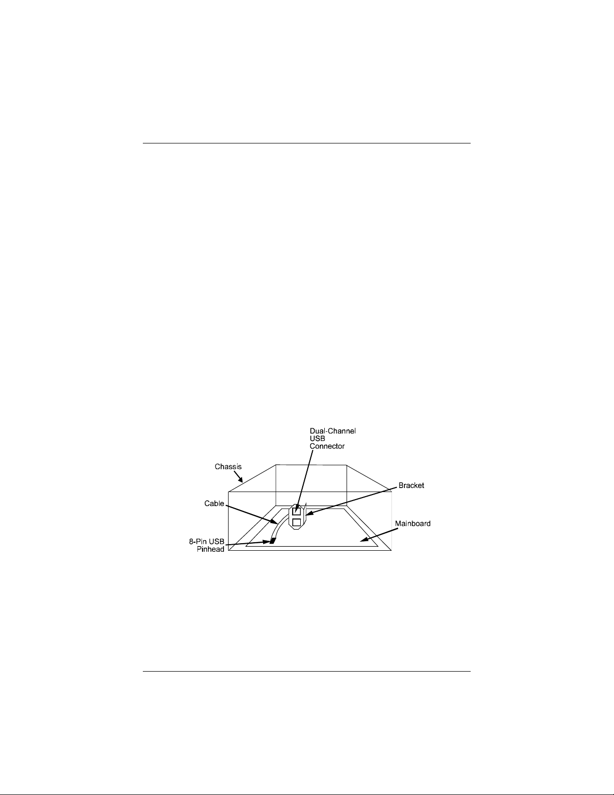
This mainboard features an optional USB connector bracket that is connected
by a cable to the onboard USB pinhead. The bracket can be installed in one of
the I/O expansion slots on the rear panel of the system, as shown in the
illustration below. It provides fast and convenient Plug and Play peripheral
connections outside your computer, allowing you take full advantage of the
universal functionality and flexibility of USB technology.

13
Installation Procedures
The PA-2005 has several user-adjustable jumpers on the board that allow you
to configure your system to suit your requirements. This chapter contains
information on the various jumper settings on your mainboard.
To set up your computer, you should follow these installation steps:
■Step 1 -
Set system jumpers
■Step 2 -
Install System RAM modules
■Step 3 -
Install the CPU
■Step 4 -
Install expansion cards
■Step 5 -
Connect cables and power supply
■Step 6 -
Set up BIOS feature (Please read Chapter Three.)
CAUTION : If you use an electric driver to install this mainboard on your
chassis, please wear a static wrist strap and the recommended electric driver
torque is from 5.0 to 8.0 kg/cm to avoid damaging chips’ pins.
Chapter 2

PA-2005 Mainboard Manual
14
Mainboard Layout
Table of contents
Other FIC Motherboard manuals


